Journal of Materials Science and Chemical Engineering, 2013, 1, 28-32
http://dx.doi.org/10.4236/msce.2013.15006 Published Online October 2013 (http://www.scirp.org/journal/msce)
Copyright © 2013 SciRes. MSCE
Microstructure of Carbon Fiber and Carbon
Reinforced Plastic
N. I. Baurova1, Wei Hao2, Ouyan g Xi ao2
1Department of Manufacture and Repair of Motor Vehicles and Road Cars, Moscow Automobile
Road State Technical University (MADI), Moscow, Russia
2Department of Material Science and Chemical Engineering, Harbin Engineering University, Harbin, China
Email: nbaurova@mail.ru
Received August 2013
ABSTRACT
This study is the investigation of the microstructure of different types of carbon fiber. They were compared with the
carbonized and graphitized fibers. Results of structural researches have been presented. It was found that the damage
varies from different pollution and the damage of the monofibers. The effect of the pollution of the monofiber was de-
termined.
Keywords: Cold Curing Epoxy Matrix; Carbon Fiber; Carbon Reinforced Plastic; Microstructure
1. Introduction
The carbon fibers (CF), and also carbon tapes and fabrics
are for a long time used in power designs of many types
of planes, as in Russia, and in foreign countries, for pro-
ducing of bearing panels of wings of plumage and fuse-
lages; for producing of coverings of three-layer panels of
various types of the antennas working in space; shovels
of turbines, nozzle blocks, nasal fairing and many other
products. Carbon fibers are also widely applied in pro-
ducing of various heating elements.
Carbon fibers represent a bunch of the monofibres,
whose quantity depends on the carbon fibers brand, can
change in very wide limits, from several thousand to ten
thousand of pieces. Each monothread represents nano-
porous strong substance which possesses unique electro-
physical properties that opens new areas of their applica-
tion, for example, as touch sensors when diagnosing de-
signs in real time [1].
Carbon fibers are received when heating cellulose (po-
liakrilonitrilny and other types) fibers. It is a difficult
process which is carried out for some stages. At the first
stage there is an oxidation at temperatures of 200˚C -
325˚C at which there is the main loss of weight and fiber
shrinkage. At the second stage carbonization is carried
out at temperatures of 1000˚C - 1500˚C, then at tem-
peratures of 2500˚C - 2800˚C graphitization. Depending
on the stage, in which the production process was inter-
rupted, or carbonized fibers with di fferent high durability,
or graphitized fibers with the high module of elasticity
are received. Simply the model of structure of carbon
fiber can be presented in the form of consistently alter-
nating blocks of crystallites which are connected among
themselves by amorphous sites [2].
2. Experimental Process
In this work the structural researches of four different
carbon fibres are conducted with the use of a raster and
electronic microscope of Phenom Company.
3. Results and Discussions
3.1. Carbon Mono-Fibres
The structure of carbon fibers is formed at a carboniza-
tion and graphitization stage as a result of course of
physical and chemical processes. Process of formation of
nanostructure of carbon fiber consists of two stages: at
the first stage education from macromolecules of nanos-
tructural educations—microfibrilla takes place. At the
second stage, in process of increase in temperature, the
macromolecule gradually from the twisted turns in linear
and diameter of microfibrilla increases. It occurs because
gradually all available in structure swore at functional
groups decay with formation of amorphous carbon chains.
Between microfibrilla there is time which inevitably
arises because of shrinkage of carbon fiber which takes
place at all stages of its oxidation (see Figure 1). In the
process of temperature increasing the number of covalent
communications with which the next microfibrilla gradu-
ally connects increases.
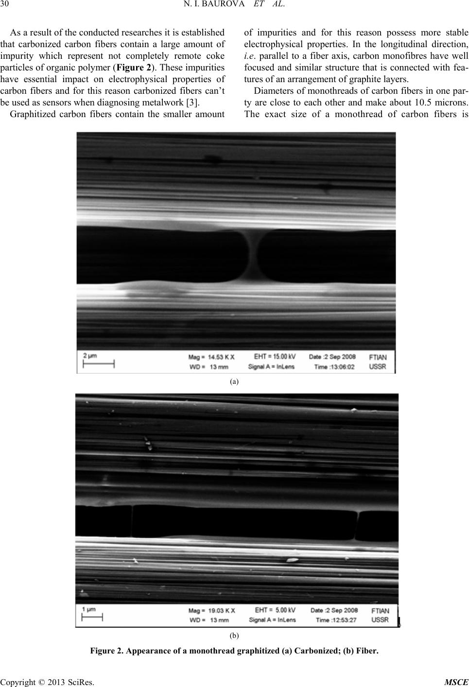
Thus, the structure of graphitized carbon fiber is
N. I. BAUROVA ET AL.
Copyright © 2013 SciRes. MSCE
29
(a) (b)
(c) (d)
(e) (f)
Figure 1. Structure of a monothread of carbon fiber: (a) Elur; (b), (c) Culon; (d) LU; (e) UKN-P; (f) UKN-2-500.
anisotropic and represents the crystallites condensed
among them and the amorphous sites consisting of atoms
of carbon (see Figure 1), these sites have respectively dark
and light colors. For cars of carbon fibers used at diag-
nosing the nanostructured axial and ring structure in rela-
tion to a fiber axis is characteristic. In the center of fiber
the areas, being characterized are located the greatest
concentration of tension. At the edges of fiber there are
areas with radial orientation. Heat-resistant inclusions
significantly differ from the main structure of fib er.
N. I. BAUROVA ET AL.
Copyright © 2013 SciRes. MSCE
30
As a result of the conducted researches it is established
that carbonized carbon fibers contain a large amount of
impurity which represent not completely remote coke
particles of organic polymer (Fig ure 2 ). These impurities
have essential impact on electrophysical properties of
carbon fibers and for this reason carbonized fibers cant
be used as se nsors whe n di a gnosin g metalwork [3].
Graphitized carbon fibers contain the smaller amount
of impurities and for this reason possess more stable
electrophysical properties. In the longitudinal direction,
i.e. parallel to a fiber axis, carbon monofibres have well
focused and similar structure that is connected with fea-
tures of an arrangement of graphite layers.
Diameters of monothreads of carbon fibers in one par-
ty are close to each other and make about 10.5 microns.
The exact size of a monothread of carbon fibers is
(a)
(b)
Figure 2. Appearance of a monothread graphitized (a) Carbonized; (b) Fiber.
N. I. BAUROVA ET AL.
Copyright © 2013 SciRes. MSCE
31
determined directly in microplasticit.
3.2. Carbon Mono-Fibres Reinforced Epoxy
Composite
For further researches, with use of carbon fibers of the
UKN-2500 brand and epoxy binding on the basis of
epoksidianovy pitch and an aminny hardener samples of
microplastics which after a full cold curing proses at
20˚C within 24 hours were tested for a gap were made,
and surfaces of destruction are investigated on an elec-
tronic microscope. Determination of nature of destruction
on the basis of which it would be possible to predict du-
rability was the purpose of these researches.
The carried-out structural analysis showed (Figure 3)
that adhesive nature of destruction takes place, i.e. the
gap occurs accurately on a surface of interphase border a
polymeric matrix—carbon fiber. Nature of destruction
elastic and black sites on a photo designate those places
where took place having dug monothreads together with
the binding.
On the basis of results of structural researches carbon
fibers it is possible to assume that pollution on the sur-
faces of monothreads representing particles of coke,
completely not removed in the course of graphitization,
dont allow to receive strong coupling of fiber and a po-
lymeric matrix and at loadings matrix peeling from fiber
takes place.
As recommendations about increase in size of adhe-
sive durability it is possible to suggest touse special fin-
ish coats with which it is necessary to process carbon
fibers surface before drawing a layer on it binding.
As other recommendation which also will allow in-
creasing durability of adhesive interaction of carbon fi-
bers and epoxy binding, it is necessary to use at carbon
fibers impregnation binding with smaller viscosity that
will allow reducing significantly thickness of a layer
binding between two next monothreads. For reduction of
viscosity two various ways can be used. The firstuse of
the solvent, the second—heating binding before impreg-
nation. At the first way carbon reinforced plastic with the
minimum thickness of a layer binding will be received,
however they will contain an additional time which will
be formed at solvent volatiliz ation in the course of a cur-
ing proses. The second way will allow receiving pore-
free composites, however, thickness of a layer binding
will be higher, than when using solution technology.
The received structures of surfaces show that this
binding doesnt possess relaxation properties and at sub-
microlevel, most likely, its multiple cr acking takes place.
Figure 3. Photo of a surface destruction of carbon reinforced plastic.
N. I. BAUROVA ET AL.
Copyright © 2013 SciRes. MSCE
32
Further at microlevel there is a fast formation of sites
where accumulation of defects take place that leads to
that at their certain concentration formation of the main
crack which, as a rule, in fragile materials develops with
a high speed will take place and quickly sprouts, and at
the development this crack is capable to cut the next
monofibres fu rther.
4. Conclusion
The conducted structural researches of carbon fibers and
microplastics on their basis showed that used carbon fi-
bers of the UKN-2500 brand has a large amount of initial
defects in the form of pollution on all their length that as
a result leads to fragile and adhesive destruction of car-
bon reinforced plastic. Use of data of carbon fibers at
production of responsible details from carbon reinforced
plastic will demand the additional measures, allowing
increasing the size of adhesive durability on interphase
zone.
5. Acknowledgements
This work was supported by the Chinese international
science and technology program (No. 2011DFR50770).
REFERENCES
[1] V. I. Kostikov, “Constructional Materials on the Basis of
Carbon in Modern Equipment—Chelyabinsk: Collection
of Scientific Works,” Modern Problems of Production
and Operation of Carbon Production, 2005, pp. 8-11.
[2] V. A. Zorin and N. I. Baurova, “Influence of External
Factors on the Accuracy of Diagnosing of Road-Building
Cars with Use of Carbon Fibers,” Construction and Road
Cars, No. 1, 2009, pp. 50-51.
[3] N. I. Baurova, “Diagnostirovaniye and Repair of Cars
about Application Polymeric Materials,” Tekhpoligraft-
sentr, 2008, 280 p.