Paper Menu >>
Journal Menu >>
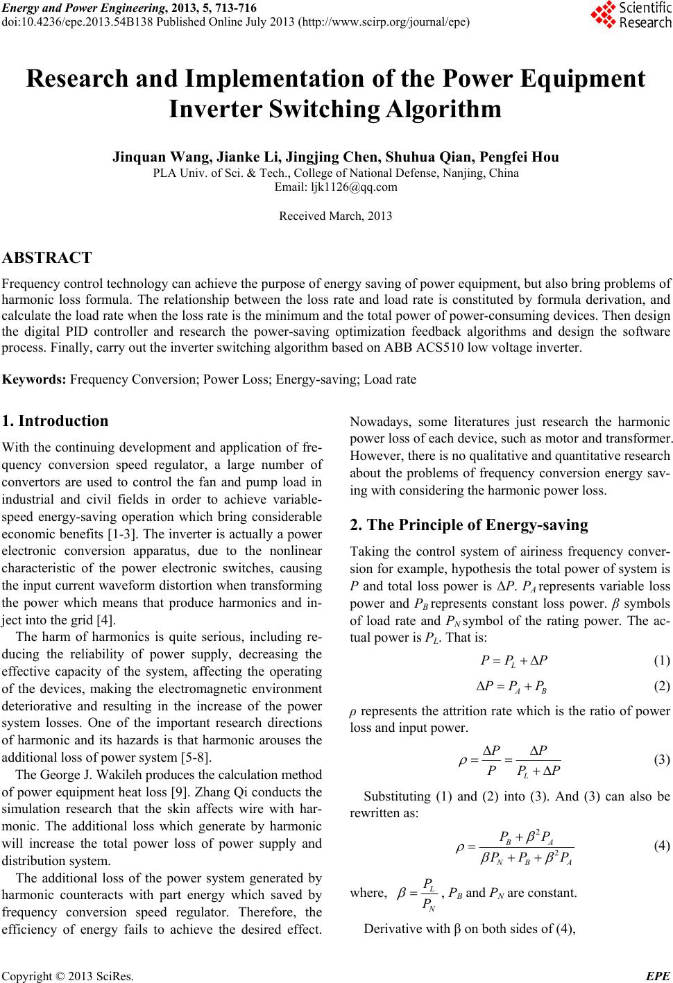 Energy and Power Engineering, 2013, 5, 713-716 doi:10.4236/epe.2013.54B138 Published Online July 2013 (http://www.scirp.org/journal/epe) Research and Implementation of the Power Equipment Inverter Switching Algorithm Jinquan Wang, Jianke Li, Jingjing Chen, Shuhua Qian, Pengfei Hou PLA Univ. of Sci. & Tech., College of National Defense, Nanjing, China Email: ljk1126@qq.com Received March, 2013 ABSTRACT Frequency control technology can achieve the purpose of energy saving of power equipment, but also bring problems of harmonic loss formula. The relationship between the loss rate and load rate is constituted by formula derivation, and calculate the load rate when the loss rate is the minimum and the total power of power-consuming devices. Then design the digital PID controller and research the power-saving optimization feedback algorithms and design the software process. Finally, carry out the inverter switching algorithm based on ABB ACS510 low voltage inverter. Keywords: Frequency Conversion; Power Loss; Energy-saving; Load rate 1. Introduction With the continuing development and application of fre- quency conversion speed regulator, a large number of convertors are used to control the fan and pump load in industrial and civil fields in order to achieve variable- speed energy-saving operation which bring considerable economic benefits [1-3]. The inverter is actually a power electronic conversion apparatus, due to the nonlinear characteristic of the power electronic switches, causing the input current waveform distortion when transforming the power which means that produce harmonics and in- ject into the grid [4]. The harm of harmonics is quite serious, including re- ducing the reliability of power supply, decreasing the effective capacity of the system, affecting the operating of the devices, making the electromagnetic environment deteriorative and resulting in the increase of the power system losses. One of the important research directions of harmonic and its hazards is that harmonic arouses the additional loss of power system [5-8]. The George J. Wakileh produces the calculation method of power equipment heat loss [9]. Zhang Qi conducts the simulation research that the skin affects wire with har- monic. The additional loss which generate by harmonic will increase the total power loss of power supply and distribution system. The additional loss of the power system generated by harmonic counteracts with part energy which saved by frequency conversion speed regulator. Therefore, the efficiency of energy fails to achieve the desired effect. Nowadays, some literatures just research the harmonic power loss of each device, such as motor and transformer. However, there is no qualitative and quantitative research about the problems of frequency conversion energy sav- ing with considering the harmonic power loss. 2. The Principle of Energy-saving Taking the control system of airiness frequency conver- sion for example, hypothesis the total power of system is P and total loss power is ΔP. PA represents variable loss power and PB represents constant loss power. β symbols of load rate and PN symbol of the rating power. The ac- tual power is PL. That is: L PP P (1) A PP P B (2) ρ represents the attrition rate which is the ratio of power loss and input power. L PP PP P (3) Substituting (1) and (2) into (3). And (3) can also be rewritten as: 2 2 BA N BA PP PP P (4) where, L N P P , PB and PN are constant. Derivative with β on both sides of (4), Copyright © 2013 SciRes. EPE 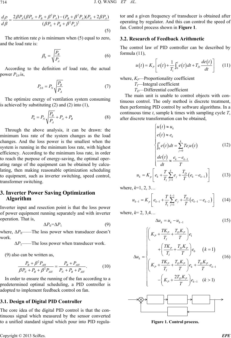 J. Q. WANG ET AL. 714 22 22 2()()( 2) () ANBA BANA NB A PPPPPPP P d dPPP (5) The attrition rate ρ is minimum when (5) equal to zero, and the load rate is: 0 B A P P (6) According to the definition of load rate, the actual power PL0 is, 0 B LN A P PP P (7) The optimize energy of ventilation system consuming is achieved by substituting (2) and (2) into (1), 0 B N A A P PP PP P B (8) Through the above analysis, it can be drawn: the minimum loss rate of the system changes as the load changes. And the loss power is the smallest when the system is running in the minimum loss rate, with highest efficiency. According to the minimum loss rate, in order to reach the purpose of energy-saving, the optimal oper- ating range of the equipment can be obtained by calcu- lating, then making reasonable optimization scheduling to equipment, such as inverter switching, speed control, transformer switching. 3. Inverter Power Saving Optimization Algorithm Inverter input and resection point is that the loss power of power equipment running separately and with inverter operation. That is, ΔP0=ΔP1 (9) where, ΔP0——The loss power when transducer doesn’t work. ΔP1——The loss power when transducer work. (9) also can be written as, 2 2. BAH BAH NBAH NB AH PP PP PPP PP P (10) In order to ensure the running of the fan according to a predetermined optimal scheduling, a PID controller is adopted to implement feedback control on fan. 3.1. Design of Digital PID Controller The core idea of the digital PID control is that the con- tinuous signal which measured by the sensor converted to a unified standard signal which pour into PID regula- tor and a given frequency of transducer is obtained after operating by regulator. And this can control the speed of fan. Control process shown in Figure 1. 3.2. Research of Feedback Arithmetic The control law of PID controller can be described by formula (11), 0 1 1t PD de t utKetetdt T Tdt (11) where, KP—Proportionality coefficient TI—Integral coefficient TD—Differential coefficient The main unit is unable to control objects with con- tinuous control. The only method is discrete treatment, then performing PID control by software algorithms. In a continuous time t, sample k times with sampling cycle T, after discrete transformation can be obtained, 00 1 k k k t i j kk ut u et e etdt Teut de tee dt T (12) 1 1 1 k D kpkj kk j T T uKee ee TT (13) where, k=1, 2, 3… 1 11 1 1 1 k D kpkj kk j T T uKee ee TT 2 (14) where, k= 2, 3,4… 1kkk uuu (15) 1 0 1 1 1 2(1) PDP P I PDP I k PDP DP Pk I DP Pk TKTK Ke TT TKTKek TT u TK TKTK k K ee TT T TK Kek T (16) Figure 1. Control process. Copyright © 2013 SciRes. EPE 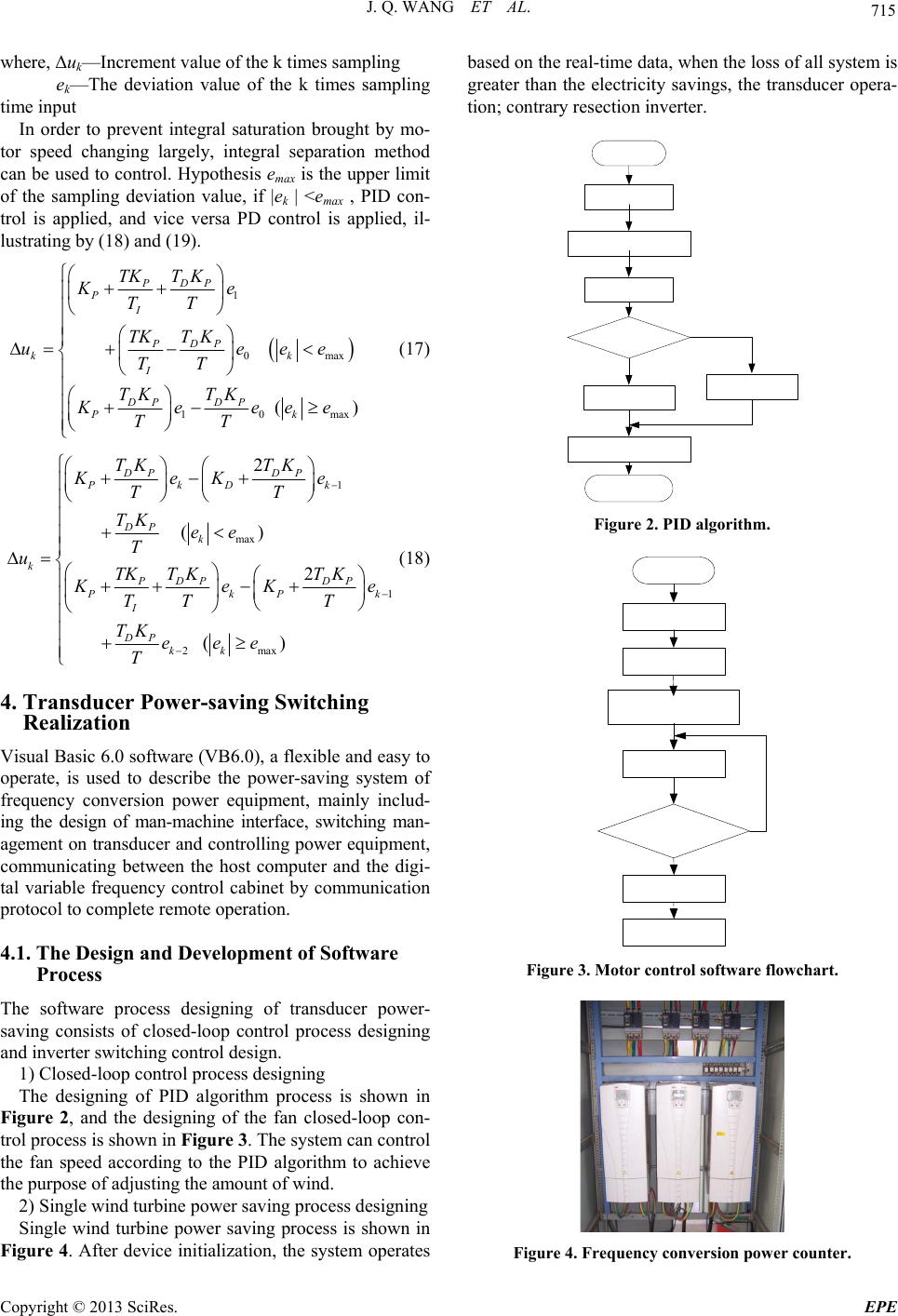 J. Q. WANG ET AL. 715 where, Δuk—Increment value of the k times sampling ek—The deviation value of the k times sampling time input In order to prevent integral saturation brought by mo- tor speed changing largely, integral separation method can be used to control. Hypothesis emax is the upper limit of the sampling deviation value, if |ek | <emax , PID con- trol is applied, and vice versa PD control is applied, il- lustrating by (18) and (19). 1 0 10 () PDP P I PDP kk I DP DP Pk TKTK Ke TT TKT K ue TT TK TK Keee TT max max ee e (17) 1 max 1 2max 2 () 2 () DP DP PkDk DP k k PDP DP PkP I DP kk TK TK KeK e TT TK ee T uTK TKTK k K eK e TT T TK eee T (18) 4. Transducer Power-saving Switching Realization Visual Basic 6.0 software (VB6.0), a flexible and easy to operate, is used to describe the power-saving system of frequency conversion power equipment, mainly includ- ing the design of man-machine interface, switching man- agement on transducer and controlling power equipment, communicating between the host computer and the digi- tal variable frequency control cabinet by communication protocol to complete remote operation. 4.1. The Design and Development of Software Process The software process designing of transducer power- saving consists of closed-loop control process designing and inverter switching control design. 1) Closed-loop control process designing The designing of PID algorithm process is shown in Figure 2, and the designing of the fan closed-loop con- trol process is shown in Figure 3. The system can control the fan speed according to the PID algorithm to achieve the purpose of adjusting the amount of wind. 2) Single wind turbine power saving process designing Single wind turbine power saving process is shown in Figure 4. After device initialization, the system operates based on the real-time data, when the loss of all system is greater than the electricity savings, the transducer opera- tion; contrary resection inverter. Figure 2. PID algorithm. Figure 3. Motor control software flowchart. Figure 4. Frequenc y c o nver sion power counter. Copyright © 2013 SciRes. EPE 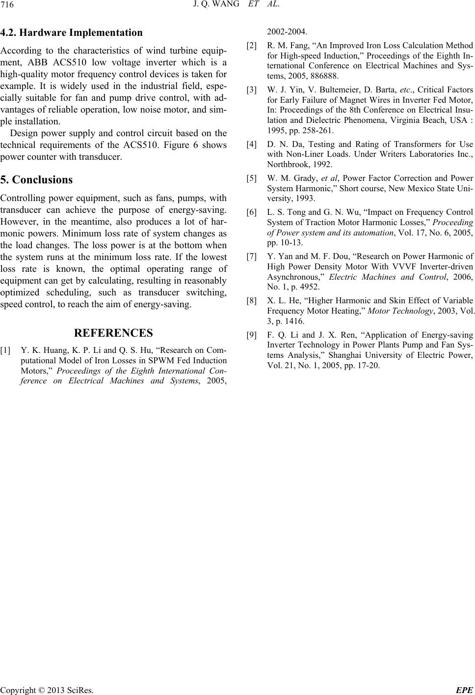 J. Q. WANG ET AL. Copyright © 2013 SciRes. EPE 716 4.2. Hardware Implementation According to the characteristics of wind turbine equip- ment, ABB ACS510 low voltage inverter which is a high-quality motor frequency control devices is taken for example. It is widely used in the industrial field, espe- cially suitable for fan and pump drive control, with ad- vantages of reliable operation, low noise motor, and sim- ple installation. Design power supply and control circuit based on the technical requirements of the ACS510. Figure 6 shows power counter with transducer. 5. Conclusions Controlling power equipment, such as fans, pumps, with transducer can achieve the purpose of energy-saving. However, in the meantime, also produces a lot of har- monic powers. Minimum loss rate of system changes as the load changes. The loss power is at the bottom when the system runs at the minimum loss rate. If the lowest loss rate is known, the optimal operating range of equipment can get by calculating, resulting in reasonably optimized scheduling, such as transducer switching, speed control, to reach the aim of energy-saving. REFERENCES [1] Y. K. Huang, K. P. Li and Q. S. Hu, “Research on Com- putational Model of Iron Losses in SPWM Fed Induction Motors,” Proceedings of the Eighth International Con- ference on Electrical Machines and Systems, 2005, 2002-2004. [2] R. M. Fang, “An Improved Iron Loss Calculation Method for High-speed Induction,” Proceedings of the Eighth In- ternational Conference on Electrical Machines and Sys- tems, 2005, 886888. [3] W. J. Yin, V. Bultemeier, D. Barta, etc., Critical Factors for Early Failure of Magnet Wires in Inverter Fed Motor, In: Proceedings of the 8th Conference on Electrical Insu- lation and Dielectric Phenomena, Virginia Beach, USA : 1995, pp. 258-261. [4] D. N. Da, Testing and Rating of Transformers for Use with Non-Liner Loads. Under Writers Laboratories Inc., Northbrook, 1992. [5] W. M. Grady, et al, Power Factor Correction and Power System Harmonic,” Short course, New Mexico State Uni- versity, 1993. [6] L. S. Tong and G. N. Wu, “Impact on Frequency Control System of Traction Motor Harmonic Losses,” Proceeding of Power system and its automation, Vol. 17, No. 6, 2005, pp. 10-13. [7] Y. Yan and M. F. Dou, “Research on Power Harmonic of High Power Density Motor With VVVF Inverter-driven Asynchronous,” Electric Machines and Control, 2006, No. 1, p. 4952. [8] X. L. He, “Higher Harmonic and Skin Effect of Variable Frequency Motor Heating,” Motor Technology, 2003, Vol. 3, p. 1416. [9] F. Q. Li and J. X. Ren, “Application of Energy-saving Inverter Technology in Power Plants Pump and Fan Sys- tems Analysis,” Shanghai University of Electric Power, Vol. 21, No. 1, 2005, pp. 17-20. |