Communications and Network, 2013, 5, 49-54
doi:10.4236/cn.2013.51B012 Published Online February 2013 (http://www.scirp.org/journal/cn)
Designing of New Data Synchronization System
Jinbin Yang, Jianping Zheng, Yanlei Shang, Junliang Chen
The State Key Lab of Networking and Switching, Beijing University of Posts and Telecommunications, Beijing, China
Email: jackieyang1987@163.com, zhengjianping@chinamobile.com, shangyl@bupt.edu.cn, chjl@bupt.edu.cn
Received 2012
ABSTRACT
As the rapid development of Wireless Communications and the popularity of the Intelligent Terminal, data synchroni-
zation has been a social focus, meanwhile, user terminal devices are increasingly diversified, traditional synchronization
technology based C/S mode has such deficiencies as insufficient amount of transmitting data and bad Real-time effi-
ciency. It has become increasingly unable to meet the needs of future development. In this paper, we proposed and de-
signed a new method and system by separating control with transmission to synchronize data to ensure Real-time data
and improve efficiency.
Keywords: Mobile Internet; Wireless Communications; Data Synchronization; Control; Transmission
1. Introduction
With the development of mobile communication tech-
nology and mobile terminal intelligence, mobile internet
technology has made a great progress. The diversity of
devices (PC, mobile, intelligent phones, Personal Digital
Assistants) gives rise to the demand for data synchroni-
zation; it gradually gets the atten tion of society.
The concept of data synchronization was derived from
storage. Simple synchronization means to perform the
same operation, while it defines the object as data. Gen-
erally we can treat it as a backup operation among dif-
ferent terminals, the terminal and the server.
The complete data synchronization should be Real-
time which means the current operation about two sides
is mirror images.
As the rapid development of mobile internet and the
popularity of intelligent terminal, data synchronization
has been a focus. Concerning about safety and respecting
for high-speed transmission have become a strong desire
of people. In the traditional data synchronization data
should be transmitted to the server firstly, then the server
transmits the data to the other clients, which means that
the same data need transmit twice; not only it wastes the
bandwidths but also reduces the Real-time performance.
So with basic control and transmission protocol in mo-
bile internet, we can find a new effective solution to im-
prove the reliability of data synchronization by separat-
ing them.
The data synchronization system proposed in this pa-
per diffs from the traditional data synchronization based
on client/server. We can consider the new system as a
client-to-client system, which transmits the basic request
instructions between the clients and the server, and it
transmits data directly between clients and clients. The
whole system mainly contains two parts: Synchroniza-
tion Control Server and the Client. The Synchronization
Server supports the basic transmission and control pro-
tocol, it also should process the instructions which come
from clients correctly; it is the hub of the entire system.
Through the use of mobile internet, the always online
server interacts with the client Real-time and keeps the
clients always online when they are transmitting data.
Another important component of the system is the Client
which sends and receives the data from other clients. The
Client mainly includes Login, Authenticating and Data
Synchronization. Users can synchronize large amounts of
data more safe, reliable and fast with the use of the Cli-
ent.
The rest of this paper is organized as follows: we de-
scribe related work in section II. Section III presents the
architecture of the data synchronization system. In sec-
tion IV, we describe the design principles of the system.
Then we display the detail design of data synchronizatio n
system in section V. In the second section from the bot-
tom we describe the specific procedure of the system.
Finally we conclude in section VII.
2. Related Work
Data synchronization is the process of establishing con-
sistency among data from a source to target data storage
and vice versa and the continuous harmonization of the
data over time. It is fundamental to a wide variety of ap-
plications, including file synchronization and mobile
device synchronization for PDAs (Personal Digital As-
Copyright © 2013 SciRes. CN
J. B. YANG ET AL.
50
sistants).[1] At present, China, USA (United States of
America), EU (European Union) and other countries
have realized the huge economic benefits of data syn-
chronization, and they are all spending lots of effort to
promote and apply it.
Personal digital assistants and other mobile computing
devices rely on synchronization protocols in order to
maintain data consistency. These protocols operate in
environments where network resources such as band-
width, memory and processing power are limited. [2]
The Session Initiation Protocol (SIP) is an IETF (In-
ternet Engineering Task Force) defined signaling proto-
col widely used for controlling communication sessions
such as voice and video calls over Internet Protocol (IP),
the protocol can be used for creating, modifying and ter-
minating two-party (unicast) or multiparty (multicast)
sessions. The SIP protocol is an Application Layer pro-
tocol designed to be independent of the underlying
Transport Layer; it can run on Transmission Control
Protocol (TCP), User Datagram Protocol (UDP), or
Stream Control Transmission Protocol (SCTP).[3]
SyncML (Synchronization Markup Language) is a
specification for a common data synchronization frame-
work for synchronizing data on networked devices.
SyncML is designed for use between mobile devices that
are intermittently connected to the network and network
services that are continuously available on the network;
we have designed and developed the data synchroniza-
tion system based on the SyncML protocol. [4] SyncML
is most commonly thought of as a method to synchronize
contact and calendar information (personal information
manager) between some type of handheld device and a
computer (personal, or network-based service), such as
between a mobile phone and a personal computer. The
new version of the specification includes support for
push email, providing a standard protocol alternative to
proprietary solutions like BlackBerry.
Rsync is a software application network protocol for
Unix-like and Windows systems that synchronizes files
and directories from one location to another while mini-
mizing data transfer using delta encoding when appropri-
ate. An important feature of rsync not found in most sim-
ilar programs/protocols is that the mirroring takes place
with only one transmission in each direction. Rsync can
copy or display directory contents and copy files, option-
ally using compression and recursion. The open-source
rsync utility reduces the time and bandwidth required to
update data across a network. Rsync uses an interactive
protocol that detects changes and sends only the changed
data [5, 6].
Traditional data synchronization system shown in
Figure 1 synchronizes data with SyncML which is based
on C/S. It contains Central Database Server, Synchroni-
zation Server, Web Server and the Client. Among it, the
Central Database Server uses LADP (Lightweight Di-
rectory Access Protocol) which is a special kind of data-
base system, specially optimizes for reading, browsing
and searching operation, widely used in basic manage-
ment of critical information, such as user information,
network resource information. Data on the Central Data-
base Server can be modified in two ways:
1) The fixed clients modify the records in the central
database through a web page by the Web Server.
2) The mobile clients access the central database and
synchronize with it through the Synchronization Server.
The main procedures of synchronization in Figure 1
can be elaborated as follows:
First of all, if the mobile client wants to synchronize
data with the fixed client, the former will send the syn-
chronization request to the synchronization server, after
the server processes the request, the connection between
the mobile client and the sev er is established, if the other
fixed client is online at the same time, the server would
also send the synchronization request to it; if the fixed
client is offline, then the server will store the request un-
til it is online next time.
Secondly, after the connection is established, the mo-
bile client synchronizes data with the server according to
corresponding synchronization protocol and algorithm,
meanwhile; the data will be stored into the central data-
base server.
Finally, the server will send the changed data to the
fixed client, if it does not change any data, some data will
be added or deleted according to the synchronization
request; if the fixed client changed some data when the
mobile client is synchronizing data with the server, then
an conflict will appear on the server, the server then
produces the same conflict data to prevent the loss of
data.
3. Architecture of New Data Synchronization
System
The new data synchronization system is developed based
on the traditional system by using control protocol SIP
and transmission protocol SyncML or rsync. The new
data synchronization system contains two parts: Server
and Client. The components are shown in Figure 2.
Figure 1. The traditional data synchronization system.
Copyright © 2013 SciRes. CN
J. B. YANG ET AL. 51
Figure 2. The new data synchronization system.
3.1. Server
The synchronization control server is mainly used to
processes and forwards the requests from the client. First
of all, all the clients must send the register information
(IP, Port and so on) to the server before they synchronize
data, it will store the key information from the request,
after storing the register information, the client will send
the control information (IP, Device Name, Data Type
and so on) to the server again, the server then processes
the client’s data to the other client, finally, if both the
clients receives control information from the server, then
the client will begin to synchronize data.
3.2. Client
The component of the client can be the mobile client or
the fixed client, which synchronizes the data from the
client to the other client by synchronization protocol. The
client can choose the other client by searching all the
online clients. When the client wan ts to synchronize d ata,
it just needs send control request to the server and waits
for responses. After receiving responses, the client can
synchronize all the data what the clients want.
4. Design Principles of Data Sychronization
System
This paper provides a novel data synchronization meth-
ods and system, we adopt to synchronize data by sepa-
rating control and transmission, detail is described as
follows:
First of all the synchronization control server receives
the clients’ registration request and store the key user
information from the request, then the synchronization
control server forwards data synchronization session in-
formation between the synchronization clients according
to its own storage, on the basis o f the session information,
direct data transmission is carried out between the syn-
chronization clients.
Depending on the context of the synchronization ses-
sion that is established between the clients, the synchro-
nization protocol (SyncML or rsync) can be adopted to
complete each type of data synchronization. The syn-
chronization session information can be described with
XML (Extensible Markup Language). [7] A concrete
example can be illustrated as follows:
<SyncContext>
<sourceIP> 100.1.1.2</source IP>
<sourcePort>10000</sou rcePort>
<destinationIP> 200.1. 1. 2</ dest i nationIP>
<destinationPort>200 00</ dest inat i onPort >
<syncSets>
<syncData>
<dataType>address book</dataType>
<syncProtocol>syncML </sy ncProt ocol >
</syncData>
<syncData>
<dataType>message</dataType>
<syncProtocol>syncML </sy ncProt ocol >
</syncData>
<syncData>
<dataType>file</dataType>
<syncProtocol>rsync</syncProtocol>
</syncData>
</syncSets>
</SyncContext>
As is seen, users do not need to save their own data on
the server in this way, if the client wants to synchronize
data with the other client, the client only need to send
control request command to the server, when the server
accepts it, the server will process and forward it to the
other client, if the control flow is established, the client
can transmit data bypass the server side, thereby the
pressure on the server side is significantly reduced.
In addition, because the process of data synchroniza-
tion separates the control and the transmission, real time
is ensured and the efficiency is improved. Moreover,
since the data is stored in the client, it also provides
greater robustness and security for the data synchroniza-
tion
5. Design Architecure of Data
Synchronization System
The whole architecture of the data synchronization sys-
tem is shown in Figure 3. The detail framework instruc-
tion of the Client is illustrated in part A and the mainly
functions in Server is shown in part B.
5.1. Framework of the Client
The whole client is divided into three layers: Application,
Bearing and Transp ort. We will make a brief introduction
of these three layers in the following.
1) Application Layer
The Application Layer is mainly to interact with users.
It helps user to choose what they want (SMS, vcard, vca-
Copyright © 2013 SciRes. CN
J. B. YANG ET AL.
52
lendar, picture, mp3 and so on) to synchronize the other
client. This layer includes SIP, which mainly controls the
register information and data synchronization session to
keep the clients’ information, and the Always Online
Protocol that keeps the client online.
2) Bearing Layer
The Bearing Layer is responsible for business logic
processing in the system; it connects the Application
Layer and the Transport Layer like a bridge. It mainly
includes the HTTP.
3) Transport Layer
The Transport Layer is mainly to establish TCP/IP
connection with other client, used to send data and re-
ceive data. The transport layer is responsible for deliver-
ing data to the appropriate application process on the
computers or phones. This involves statistical multiplex-
ing of data from different application processes, i.e.
forming data packets, and adding source and destination
port numbers in the header of each transport-layer data
packet.
5.2. Server Functions
The server of data synchronization system contains two
modules: Business Module and Management Module.
1) Business Module
This module consists of two parts: SIP Control Server
and AOL Server, the former mainly provides the regis-
tration, login and control function. The latter mainly
keeps the client onlin e while synchronizing data.
During the registration process, if the user is not regis-
tered, the user can register to the server by inputting
username and password into the client, at the same time,
the IP and the device name is recorded in the server.
During the process of login, if the r egistration above is
successful, then the user can sign in; otherwise an error
message will be popped up on the screen. Moreover, this
Figure 3. The architecture of data synchronization system.
module also offers the setting function which enables
users to set the IP address of server and save one’s user-
name and password.
During the control process, when the user chooses to
synchronize the data, the control module will work, then
an dialogue will be shown to the user, in this dialogue,
other registered online clients will be displayed to the
user, user can choose which clients they want to build the
connection.
2) Management Function
The module includes user management, view man-
agement and device management.
User management is used to verify the user authority,
it also offers the basic function wh ich adds or deletes on e
user by the administrator.
View management is mainly to interact with an ad-
ministrator to interact with administrator who can also
monitor the clients’ synchronization progress conven-
iently.
Device Management is to add, modify or delete one
device by the administrator; the administrator can also
examine detailed information about each device.
6. Specific Procedure
As is seen the detail design principles and architecture
above, we will describe the detail procedure (shown in
Figure 4) in this section. The flow chart mainly con tains
four stages, we will introduce them respectively.
1) Synchronization Server Register / Always Online
Figure 4. The detail procedure of data sync hronization.
Copyright © 2013 SciRes. CN
J. B. YANG ET AL. 53
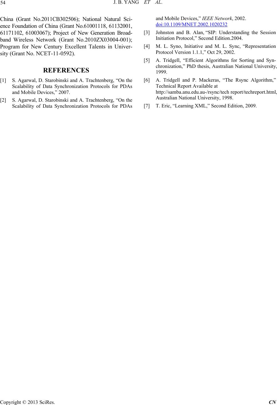
In Figure 4, step1- step10 corresponds to this stage;
the user device sends periodic registration to the syn-
chronization control server to keep the client online that
means to maintain the user device’s IP address, port and
other information stored in the synchronization control
server. The user device can also send the registration
information which contains the changed message to the
server if changing is detected. The always online module,
receiving the synchronization client’s message, handles
them and keeps the client online.
Step 1: UE1 sends unauthorized register request to the
synchronization server, so as to the Server can get the
register information. Described in the general registration
information includes the user device’s IP address, port
number.
Here the message can be carried with SIP.
Step 2: Synchronization control server authenticates it
through the back-end, if the user’s IP address is not in the
database, then the Server will send the unauthenticated
401 message to UE1, secure authentication token is re-
quired.
Step 3: According to the token, UE1 marks it and en-
crypts the password, it will send authorized register re-
quest to the Server.
Step 4: The Server accepts this register request, de-
crypts it and stores it into local datab ase, then it will send
200 OK message in response.
Step 5: After successful registration, the client will re-
peat sending the register request to the Server to keep it
online, the in terval generally is 60 seconds.
Step 6-10: UE2 will send the same register request to
UE1, after successful registration it will repeat sending
register request to the Server to keep on line.
2) Establish data synchronization session
Through the synchronization control server, the user
device interacts data synchronization session information
with other user device, so the data synchronization ses-
sion is established between the user devices. This stage
corresponds to step11-step18 in Figure 4.
Step 11: After successful register, UE1 sends the invite
request message which contains basic session informa-
tion such as Type and Protocol and so on.
Step 12: The synchr onization server sends trying mes-
sage which means the invite message is being processed.
Step 13: UE1 will be authenticated, if it is certified,
the Server will check via header field of the invite mes-
sage whether it contains the IP address of UE1, if it car-
ries, then the Server will insert its own IP address to the
via header field, finally, the Server will put forward the
invite message to UE2.
Step 14: UE2 accepts the invite message and sends
trying message which means it is processing it.
Step 15: If UE2 has got the message, it will match the
data type and the protocol, and packages its own message
(IP address, port) into th e 200 OK messages.
Step 16: The Server gets the 200 OK messages and
forwards it to UE1.
Step 17: After UE1 receives the 200 OK messages, it
will send acknowledge message to ensure secure and
reliable connection.
Step18: UE2 receives the acknowledge message to
confirm it, so the SIP control connection is established,
and it is ready for synchron izing data.
3) Data synchronization
This stage corresponds to step 19 in Figure 4, accord-
ing to data synchronization session mentioned above,
directly data transmission is conducted between the two
devices, which the synchronization protocol can be
SyncML or rsync on the basis of different da ta types.
Step 19: According to data synchronization session
information UE1 will choose consulted synchronization
protocol with UE2 against different data types, then be-
gins to synchronize data.
4) Data synchronization ends
In the last four steps (step 20-step23) in Figure 4,
when we need to end the data synchronization session,
the user device can end the session with the other device
by the synchro nizat i on co nt r o l serve r.
Step 20: UE1 sends bye message to the Synchroniza-
tion Server to request to end the synchronization this
time.
Step 21: The Synchronization receives the bye mes-
sage and response it to end this connection.
Step 22: The Synchronization Server sends bye mes-
sage to UE2 to end this connection and prepares for re-
cycling the session information; after receiving the 200
OK messages from UE2, the Server will delete related
information about synchronization session information,
so it realizes to recycle them above.
Step 23: UE2 ends the synchronization transmission
between UE1 and UE2, finally, it will send 200 OK
messages to ensure successful conclusion of the syn-
chronous da t a .
7. Conclusions
The development of mobile internet and intelligent ter-
minal bring us many new ways to improve the efficiency
and the speed of data synchronization. We can use these
technologies to set up a comprehensive and effective
synchronization system to synchronize data timely. This
system should be much helpful for those clients to have a
high speed to synchronize data and to improve effi-
ciency.
8. Acknowledgements
The work presented in this paper was supported by the
National Grand Fundamental Research 973 Program of
Copyright © 2013 SciRes. CN
J. B. YANG ET AL.
Copyright © 2013 SciRes. CN
54
China (Grant No.2011CB302506); National Natural Sci-
ence Foundation of China (Grant No.61001118, 61132001,
61171102, 61003067); Project of New Generation Broad-
band Wireless Network (Grant No.2010ZX03004-001);
Program for New Century Excellent Talents in Univer-
sity (Grant No. NCET- 11-0592).
REFERENCES
[1] S. Agarwal, D. Starobinski and A. Trachtenberg, “On the
Scalability of Data Synchronization Protocols for PDAs
and Mobile Devices,” 2007.
[2] S. Agarwal, D. Starobinski and A. Trachtenberg, “On the
Scalability of Data Synchronization Protocols for PDAs
and Mobile Devices,” IEEE Network, 2002.
doi:10.1109/MNET.2002.1020232
[3] Johnston and B. Alan, “SIP: Understanding the Session
Initiation Protocol,” Second Edition.2004.
[4] M. L. Syno, Initiative and M. L. Sync, “Representation
Protocol Version 1.1.1,” Oct 29, 2002.
[5] A. Tridgell, “Efficient Algorithms for Sorting and Syn-
chronization,” PhD thesis, Australian National University,
1999.
[6] A. Tridgell and P. Mackeras, “The Rsync Algorithm,”
Technical Report Available at
http://samba.anu.edu.au-/rsync/tech report/techreport.html,
Australian National University, 1998.
[7] T. Eric, “Learning XML,” Second Edition, 2009.