Communications and Network, 2013, 5, 29-33
doi:10.4236/cn.2013.51B008 Published Online February 2013 (http://www.scirp.org/journal/cn)
Development of Wireless Light Control Sys tem
Based on Zigbee
Changfei Guo, Xiaoping Zou, Chaoting Ma, Rongrong Zhang
Beijing Key Laboratory for Sensor, Beijing Information Science and Technology University, Beijing, China
Email: xpzou2005@gmail.com
Received 2012
ABSTRACT
This paper presents a solution to wireless ligh t control system based on Zigbee. Overall design framework of the system
was introduced and analyzed in detail, which contained realization of hardware design. The Zigbee wireless light con-
trol system was established based on CC2430-chip of Texas Instruments (TI). In this paper, we achieved designing
Printed Circuit Board (PCB) for sensor nodes as end device and coordinator in Protel DXP 2004 and also wrote C codes
in IAR embedded workbench development tool to form wireless network. Test results of system show that lights on end
device or router in Zigbee wireless sensor networks (WSN) can be controlled by another switch on coordinator, which
achieved remotely wireless intelligence light control.
Keywords: Wireless Light Control; Zigbee; PCB; WSN
1. Introduction
With the emergence of the internet of things, the princi-
ples that gave rise to the internet are now leading to a
new kind of network of e ve ryday devices, an “Internet-0”
[1]. As a new short-range wireless communication tech-
nology, Zigbee aims at solving the function of internet
among different hardware devices, which have powerful
potential applying in intelligence control [2] such as in-
dustry, medical and home.
To realize intercommunication among different hard-
ware devices, we built wireless sensor networks (WSN)
to achieve wireless light control. In this paper, design and
implementation of system were given and analyzed in
detail.
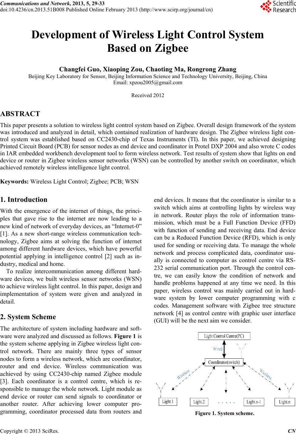
2. System Scheme
The architecture of system including hardware and soft-
ware were analyzed and discussed as follows. Figure 1 is
the system scheme applying in Zigbee wireless light con-
trol network. There are mainly three types of sensor
nodes to form a wireless network, which are coordinator,
router and end device. Wireless communication was
achieved by using CC2430-chip named Zigbee module
[3]. Each coordinator is a control centre, which is re-
sponsible to manage the whole network. Light module as
end device or router can send signals to coordinator or
another router. After achieving lower computer pro-
gramming, coordinator processed data from routers and
end devices. It means that the coordinator is similar to a
switch which aims at controlling lights by wireless way
in network. Router plays the role of information trans-
mission, which must be a Full Function Device (FFD)
with function of sending and receiving data. End device
can be a Reduced Function Device (RFD), which is only
used for sending or receiving data. To manage the whole
network and process complicated data, coordinator usu-
ally is connected to computer as control centre via RS-
232 serial communication port. Through the control cen-
tre, we can easily know the condition of network and
handle problems happened at any time we need. In this
paper, wireless control was mainly carried out in hard-
ware system by lower computer programming with c
codes. Management software with Zigbee tree structure
network [4] as control centre with graphic user interface
(GUI) will be the next aim we consider.
Figure 1. System scheme.
Copyright © 2013 SciRes. CN