Open Journal of Microphysics, 2013, 3, 1-4
doi:10.4236/ojm.2013.33B001 Published Online August 2013 (http://www.scirp.org/journal/ojm)
Gas-phase Synthesis of Carbon Nanostructures and
Composites
Kh. A. Abdullin1, D. G. Batryshev1, Y. V. Chikhray2, M. T. Gabdullin1,
D. V. Ismailov1, A. K. Togambaeva2
1Al-Farabi KazNU, National Nanotechnological Laboratory of Opened Type, al-Farabi Str, Almaty, Kazakhstan
2Al-Farabi KazNU, Institute of Experimental and Theoretical Physics, al-Farabi Str, Almaty, Kazakhstan
Received May, 2013
ABSTRACT
CVD synthesis of carbon nanotubes was carried out using ethanol paralysis in tubular quartz reactor at atmospheric
pressure of hydrogen. Ni, Co and Fe catalyst were used for CNT deposition. The CNT samples obtain ed under various
experimental conditions were studied by scanning electron microscopy (SEM), X-ray fluorescent microanalysis and
Raman spectroscopy. The ratio of ID/IG of D ( ~1360 cm-1) and G (~1580 cm-1) Raman peaks was monitored to estimate
the crystalline of graphite-like material. The optimal conditions for synthesis of CNTs on the Si-substrates and on the
SiO2-based fiberglass were determined. MWNT were produced with 25-30 nm diameters, up to 30 microns in length
and with crystallite size La from 2.7 nm to 7 nm. DC electrical properties of carbon composites MWNT/SiO2-fiberglass
were examined. Specific resistance was about 10 cm and more depending on CNT content. It was found that the resis-
tivity of the carbon composites MWNT/SiO2 is sensitive to external pressure. Processing of composite with binding
polymer significantly improves stability and repeatability of its voltage-current characteristics.
Keywords: Carbon Nanotubes (CNT); Chemical Vapor Deposition (CVD); Scanning Electron Microscopy (SEM);
Raman Spectroscopy
1. Introduction
Carbon nanotubes (CNT) have found applications in dif-
ferent areas, such as semiconductor structures on unipo-
lar transistors, field emitters, gas sensors, solar cells, cat-
alysts, ultra capacitors etc [1-9]. CNT-based na-
no-structured composite materials and reinforced poly-
mers have been developed for use in a variety of prod-
ucts. Increasingly wide range of applications of CNT
requires a big amount of low cost materials. Therefore,
the development of low cost techniques of CNT synthe-
sis still remains actual. In the present work, we fabricate a
nanostructure carbon with nickel impurities, carbon na-
notubes and carbon-related composites by gas-phase de-
position.
2. Experiment
The synthesis of CNT by chemical vapor deposition
(CVD) was carried out in hydrogen under the atmos-
pheric pressure. The CVD process was carried out in a
tube quartz reactor (diameter 25 mm) within a tube fur-
nace at temperatures between 600 and 900℃. Ethanol
was used as a carbon source. When the necessary tem-
perature of synthesis was obtained, sweep gas comes via
the bubbler filled with ethanol at room temperature.
Single side polished p-type <111> silicon substrates
with SiO2 layers and catalyst layer of Ni ( 5÷10 nm thick)
were used as a substrate for CNT growth by fixed bed
CVD method. Thin nickel films were deposited on Si
substrates by electron-beam evaporation of Ni target.
Silica based glass fiber was also used as a substrate for
fixed bed growth of CNT. A catalyst was deposited by
wet impregnation method. First of all, 2 g of nickel ni-
trate and 2 g of cobalt nitrate were dissolved into 100 ml
distilled water and 10 g of the silica based glass fiber was
immersed in the solution for 24 hours at ambient tem-
perature. Then the solution was poured out and the glass
fiber was dried at 100℃ for 24 h in an oven. The fibers
were loaded in the reactor, filling the entire diameter of
the tube quartz reactor. Nitrates were reduced under hy-
drogen flow while the desired temperature of CNT
growth is being achieved.
The Fe was used a catalyst and TiO2 powders with
granule size of ~0.2 m was used as a catalyst carrier in
the fluidized bed method. The Fe-loaded TiO2 powder
was prepared by wet impregnation method during proc-
essing of the powder in water solution of iron chloride
for 12 hours, with the following drying at 105℃. The
synthesis was carried out in vertical reactor under hy-
drogen flow.
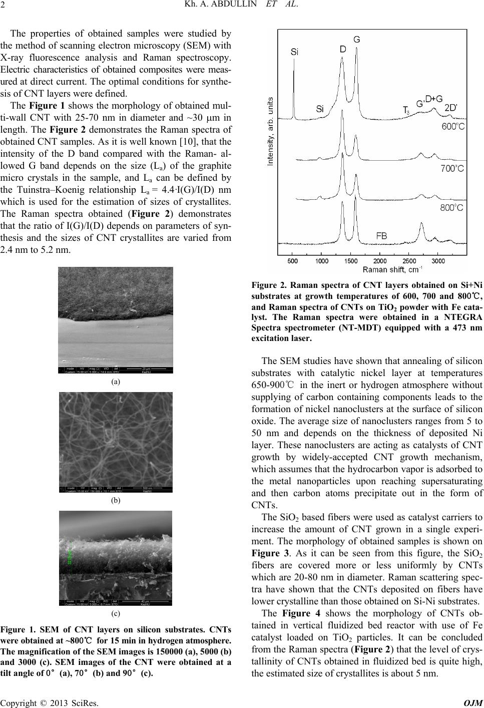
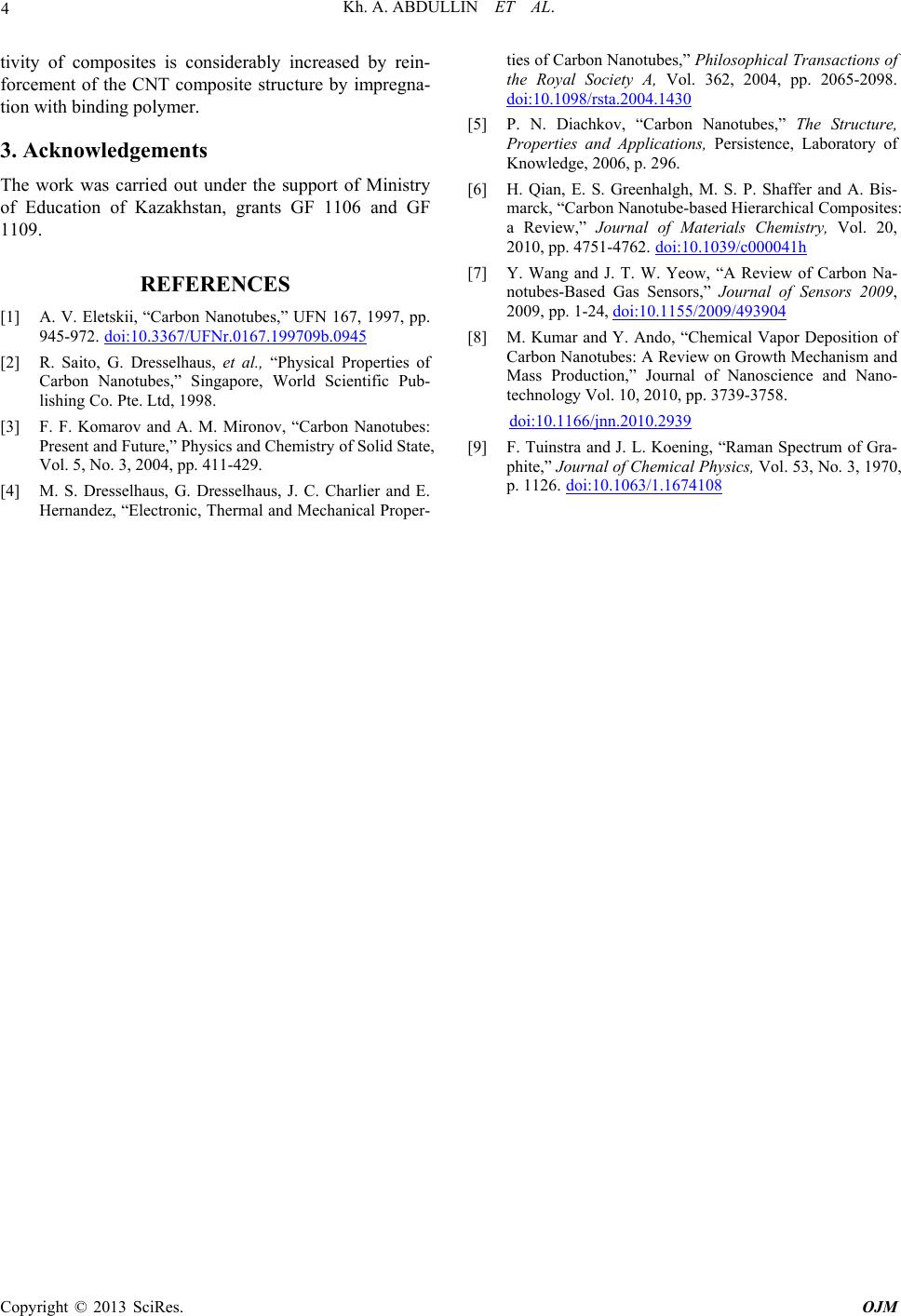
Copyright © 2013 SciRes. OJM