Paper Menu >>
Journal Menu >>
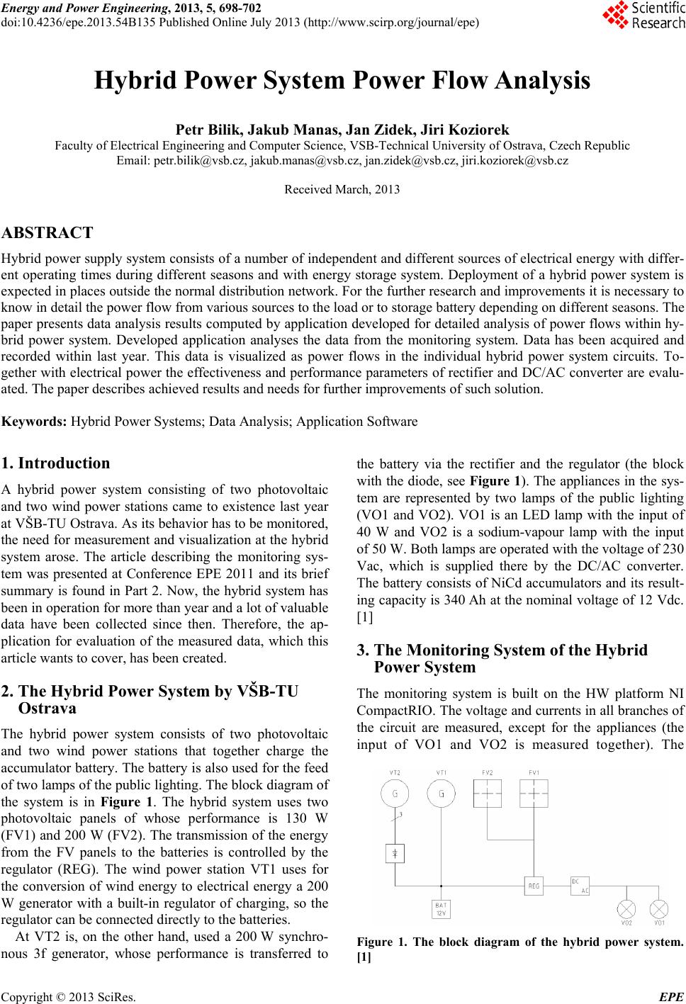 Energy and Power Engineering, 2013, 5, 698-702 doi:10.4236/epe.2013.54B135 Published Online July 2013 (http://www.scirp.org/journal/epe) Hybrid Power System Power Flow Analysis Petr Bilik, Jakub Manas, Jan Zidek, Jiri Koziorek Faculty of Electrical Engineering and Computer Science, VSB-Technical University of Ostrava, Czech Republic Email: petr.bilik@vsb.cz, jakub.manas@vsb.cz, jan.zidek@vsb.cz, jiri.koziorek@vsb.cz Received March, 2013 ABSTRACT Hybrid power supply system consists of a number of ind ependent and different sources of electrical energy with differ- ent operating times during different seasons and with energy storage system. Deployment of a hybrid power system is expected in places outside the normal distribution network. For the further research and improvements it is necessary to know in detail the power flow from various sources to the load or to storage battery depending on different seasons. The paper presents data analysis results computed by application developed for detailed analysis of power flows within hy- brid power system. Developed application analyses the data from the monitoring system. Data has been acquired and recorded within last year. This data is visualized as power flows in the individual hybrid power system circuits. To- gether with electrical po wer the effectiveness and performance parameters of rectif ier and DC/AC converter are evalu- ated. The paper describes achieved results and needs for further improvements of such solution. Keywords: Hybrid Power Systems; Data Analysis; Application Software 1. Introduction A hybrid power system consisting of two photovoltaic and two wind power stations came to existence last year at VŠB-TU Ostrava. As its behavior has to be monitored, the need for measurement and visualization at the hybrid system arose. The article describing the monitoring sys- tem was presented at Conference EPE 2011 and its brief summary is found in Part 2. Now, the hybrid system has been in operation for more than year and a lot of valu able data have been collected since then. Therefore, the ap- plication for evaluation of the measured data, which this article wants to cover, has been created. 2. The Hybrid Power System by VŠB-TU Ostrava The hybrid power system consists of two photovoltaic and two wind power stations that together charge the accumulator battery. The battery is also used for the feed of two lamps of the public lighting. The block diagram of the system is in Figure 1. The hybrid system uses two photovoltaic panels of whose performance is 130 W (FV1) and 200 W (FV 2). The transmission of the energy from the FV panels to the batteries is controlled by the regulator (REG). The wind power station VT1 uses for the conversion of wind energy to electrical energy a 200 W generator with a built-in regulator of charging, so the regulator can be connected directly to the batteries. At VT2 is, on the other hand, used a 200 W synchro- nous 3f generator, whose performance is transferred to the battery via the rectifier and the regulator (the block with the diode, see Figure 1). The appliances in the sys- tem are represented by two lamps of the public lighting (VO1 and VO2). VO1 is an LED lamp with the input of 40 W and VO2 is a sodium-vapour lamp with the input of 50 W. Both lamps are operated with the voltage of 230 Vac, which is supplied there by the DC/AC converter. The battery consists of NiCd accumulators and its result- ing capacity is 340 Ah at the nominal voltage of 12 Vdc. [1] 3. The Monitoring System of the Hybrid Power System The monitoring system is built on the HW platform NI CompactRIO. The voltage and currents in all branches of the circuit are measured, except for the appliances (the input of VO1 and VO2 is measured together). The Figure 1. The block diagram of the hybrid power system. [1] Copyright © 2013 SciRes. EPE  L. D. NIEM ET AL. 699 individual measuring points are shown in Figure 2. The monitoring system does not take any electrical energy from the batteries of the hybrid power system; its feed ing is dealt with separately and provides uninterrupted op- eration (UPS). [1] All the measuring HW is located in the existing out- door distribution box where there is the whole electrical equipment of the hybrid power system. This box pro- vides protection against weather conditions, but it is not thermally insulated. This places increased demands on the operating temperature of e a ch component. [1] All the components are placed on a metal structure lo- cated in the box. The dimensions of the free internal space of the box must be taken into consideration when choosing the components and the layout design. [1] The measured data are stored in text files (daily re- cords). The current measured data are visualized on the web- site by means of a web server (Figure 3), which is oper- ated on a remote PC. The data are also backed up on the PC and can be downloaded by authorized users with the help of the FTP access. Figure 2. The block diagram of the measured system and the measuring points. [1] Figure 3. Visualization of the measured data with the help of the w eb interface . Copyright © 2013 SciRes. EPE  L. D. NIEM ET AL. 700 4. Application for Evaluation of the Measured Data The developed application for evaluation of the measured data (application) enables graphical display (Figure 4) of the measured and computed data (performance streams, component efficiency). The users can specify the accu- rate time period (the minimum resolution is 1 day) or they can choose from the menu “The last 3 days”, “The last week”, …, “The last year” (Figure 5). The application enables to display up to 4 parameters in the graph at the same time, when each parameter has its own vertical axis with its scaling. The application then processes these data statistically so that the data are di- vided into certain time parts so that the total number of samples to the graph was approximately a thousand for each course of the parameter. The algorithm of searching for the minimum and maximum value of the parameter and their display together with their time in the correct order is the reduction of the data. [3] Examples of the Measured Data in the Graphic Form For the illustration purposes, the results are shown in the graphic form. It is necessary to point out that the applica- tion serves for evaluation of the current state of the hy- brid system and for its optimization, so it is necessary to take the displayed results with a pinch of salt. Figure 4. GUI of the application created for the display of the data evaluated in the graph. Figure 5. GUI of the application created for the evaluated data selection. Copyright © 2013 SciRes. EPE  L. D. NIEM ET AL. 701 So as something was not d isplayed in the optimum scale in the graphs, the courses for only one day are shown here. Figure 6 shows charging of the battery from photo- voltaic panels. Parameter “P3” is the performance sup- plied to the regulator, “P3_REG” is the performance supplied from the regulator, “EF_ REG_FVtoBAT” is the efficiency of the regulator (from the photovoltaic panels to the battery). The efficiencies are computed for per- formances exceeding 10 W (a user-selectable value), so the efficiency graph is not continuous. Figures 7 and Figure 8 show the discharging of the battery into the lights (VO1 an d VO2). In Figure 7, there is parameter “P3_REG”, i.e. the performance supplied from the battery to the regulator. Parameter “P4” is the performance flowing from the regulator to the DC/AC converter and “EF_REG_BATtoCONV” is the efficiency of the regulator (from the battery to the converter). Fig- ure 8 shows parameter “P5”, i.e. the performance con- sumed in the lights, “EF_ CONV” is the efficiency of the converter and “U1” is the voltage at the battery. In the time of approximately 6/7/ 2011 2:15, the regulator eva- luated that the voltage at the battery is low and stopped its discharging. 5. Conclusions The goal of this article was to describe the application for evaluation of the measured data from the hybrid power system consisting of two photovoltaic and two wind power stations. Figure 6. An example of the application output (charging of the battery from photovoltaic panels). Figure 7. An example of the application output (discharging of the battery into the lights). Copyright © 2013 SciRes. EPE  L. D. NIEM ET AL. 702 Figure 8. An example of the application output (discharging of the battery into the lights). The application allows comfortable and efficient off- line analysis of internal phenomena in the hybrid power system at VSB-Technical University of Ostrava. The first version of application was developed in 2011 and it is still improved according to final user needs. The actual version of the monitoring system from 2013 provides basic monitoring of EMC quantities also and thus it is used for educational purposes. New features were mostly allowed by using latest version of graphical development environment LabVIEW by National Instruments which made big improvement in cRIO controller and cRIO FPGA programming efficiency. Issues like harmonic components on AC parts of circuit and even DC parts of circuit can be visualized to students. To visualize EMC phenomena in understandable way is very important for educational purposes [2]. When the application NI DIAdem for the analysis of the measured data is used, the creation of measurement protocols is much comfortable and faster. These signifi- cant time savings enable the users to concentrate their time and energy on substantial issues during the research of the hybrid system. The application uses the concept of virtual instrumentation, so it is flexible and expandable according to the future requirements without the need of higher time sources. 6. Acknowledgements This work was supported in part by The Ministry of Education, Youth and Sports of Czech Republic under the project KONTAKT II registration number LH12183 and in part by VSB-Technical University Ostrava, FEECS under the project SGS registration number SP2013/203. REFERENCES [1] J. Kvapil, P. Bilik and S. Misak, “Monitoring System of the Hybrid Power System,” In 12th International Scien- tific Conference Electric Power Engineering EPE 2011, pp. 1-3. Kouty nad Desnou, Czech Republic, 2011. [2] P. Drabek and V. Kus, “The Education of EMC at the UWB,” In Electrical Power Quality and Utilization EP- QU 2011, pp. 1-6, Lisboa, Portugal, 2011. [3] M. Tutsch, P. Vojcinak, J. Koziorek and M. Skrepek, “Using Automated Evaluation of Effi- ciency for Photovoltaic Power Plant,” In Proceed- ings of the 16th IEEE Symposium on Emerging Technologies and Factory Automation, ETFA 2011, 5-9 September 201 1, T o ulouse, F ran ce, pp. 1-4 , Copyright © 2013 SciRes. EPE |