Paper Menu >>
Journal Menu >>
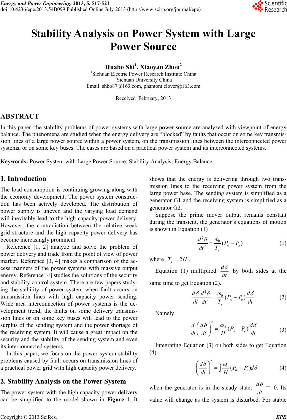 Energy and Power Engineering, 2013, 5, 517-521 doi:10.4236/epe.2013.54B099 Published Online July 2013 (http://www.scirp.org/journal/epe) Stability Analysis on Power System with Large Power Source Huabo Shi1, Xiaoyan Zhou2 1Sichuan Electric Power Research Institute China 2Sichuan University China Email: shbo87@163.com, phantom.clover@163.com Received February, 2013 ABSTRACT In this paper, the stability problems of power systems with large power source are analyzed with viewpoint of energy balance. The phenomena are studied when the energy delivery are “blocked” by faults that occur on some key transmis- sion lines of a large power source within a power system, on the transmission lines between the interconnected power systems, or on some key buses. The cases are based on a practi c a l power system and its interconnected systems. Keywords: Power System with Large Power Source; Stability Analysis; Energy Balance 1. Introduction The load consumption is continuing growing along with the economy development. The power system construc- tion has been actively developed. The distribution of power supply is uneven and the varying load demand will inevitably lead to the high capacity power delivery. However, the contradiction between the relative weak grid structure and the high capacity power delivery has become increasingly prominent. Reference [1, 2] analyze and solve the problem of power delivery and trade from the point of view of power market. Reference [3, 4] makes a comparison of the ac- cess manners of the power systems with massive output energy. Reference [4] stud ies the solution s of the security and stability con trol system. There are few papers study- ing the stability of power system when fault occurs on transmission lines with high capacity power sending. Wide area interconnection of power systems is the de- velopment trend, the faults on some delivery transmis- sion lines or on some key buses will lead to the power surplus of the sending system and the power shortage of the receiving system. It will cause a great impact on the security and the stability of the sending system and even its interconnected systems. In this paper, we focus on the power system stability problems caused by fault occurs on transmission lines of a practical power grid with high capacity power delivery. 2. Stability Analysis on the Power System The power system with the high capacity po wer delivery can be simplified to the model shown in Figure 1. It shows that the energy is delivering through two trans- mission lines to the receiving power system from the large power base. The sending system is simplified as a generator G1 and the receiving system is simplified as a generator G2. Suppose the prime mover output remains constant during the transient, the generator’s equations of motion is shown in Equation (1) 20 2( me j dPP T dt ) (1) where 2 j TH . Equation (1) multiplied d dt by both sides at the same time to get Equation (2). 20 2() me j dd d PP dt Tdt dt (2) Namely 2 0() me dd d PP dt dtHdt (3) Integrating Equation (3) on both sides to get Equation (4) 2 0() me dPPd dt H (4) when the generator is in the steady state, d dt = 0. Its value will change as the system is disturbed. For stable Copyright © 2013 SciRes. EPE 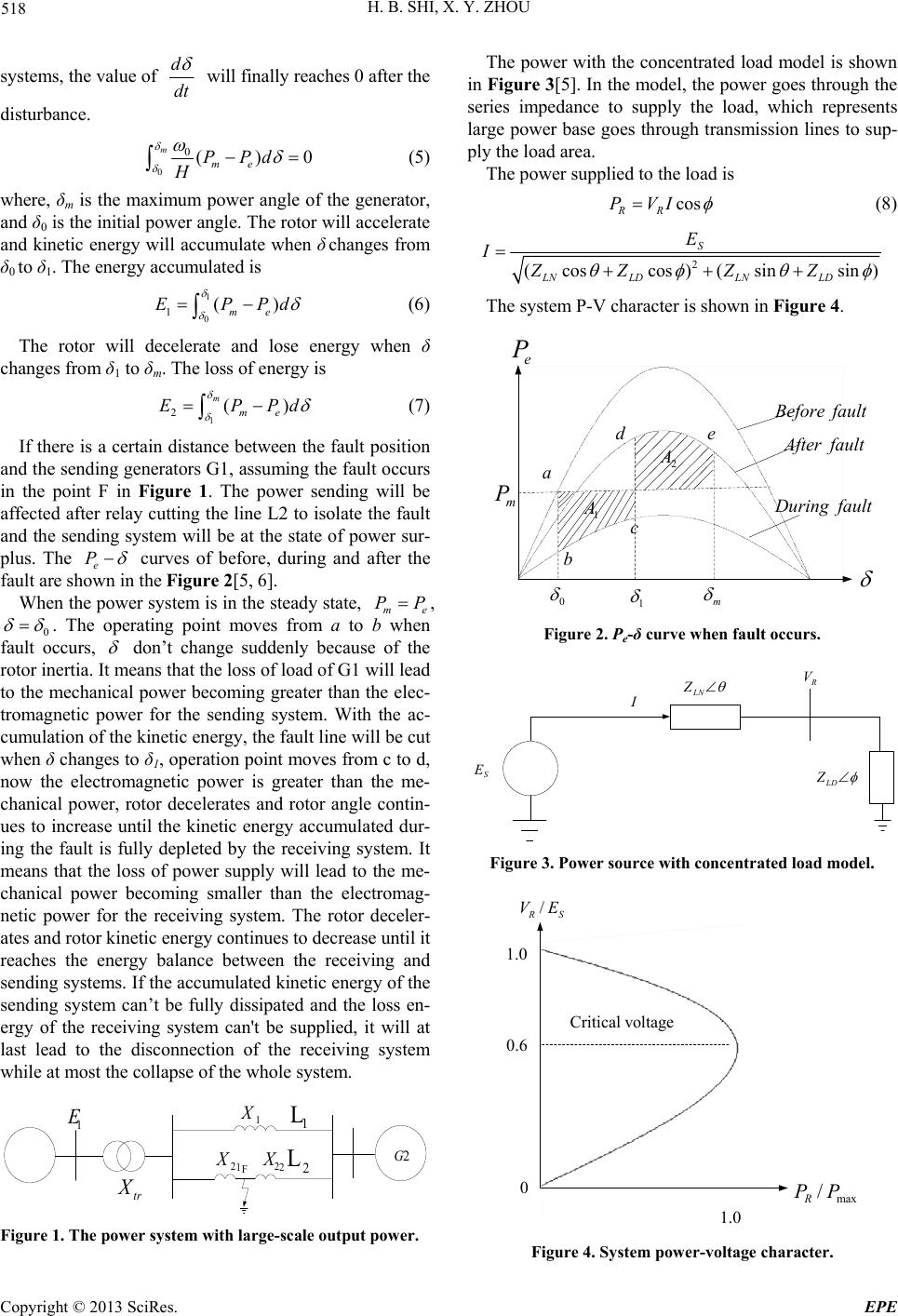 H. B. SHI, X. Y. ZHOU 518 systems, the value of d dt will finally reaches 0 after the disturbance. 0 0() m me PPd 0 H (5) where, δm is the maximum power angle of the generator, and δ0 is the initial power angle. The rotor will accelerate and kinetic energy will accumulate when δ changes from δ0 to δ1. The energy accumulated is 1 0 1() me EPP d (6) The rotor will decelerate and lose energy when δ changes from δ1 to δm. The loss of energy is 1 2() m me EPP d (7) If there is a certain distance between the fault position and the sending generators G1, assuming the fault occurs in the point F in Figure 1. The power sending will be affected after relay cutting the line L2 to isolate the fault and the sending system will be at the state of power sur- plus. The e P curves of before, during and after the fault are shown in the Figure 2[ 5, 6]. When the power system is in the steady state, me PP , 0 . The operating point moves from a to b when fault occurs, don’t change suddenly because of the rotor inertia. It means that the loss of load of G1 will lead to the mechanical power becoming greater than the elec- tromagnetic power for the sending system. With the ac- cumulation of the kinetic energy, the fault line will be cut when δ changes to δ1, operation point moves from c to d, now the electromagnetic power is greater than the me- chanical power, rotor decelerates and rotor angle contin- ues to increase until the kinetic energy accumulated dur- ing the fault is fully depleted by the receiving system. It means that the loss of power supply will lead to the me- chanical power becoming smaller than the electromag- netic power for the receiving system. The rotor deceler- ates and rotor kinetic energy continues to decrease until it reaches the energy balance between the receiving and sending systems. If the accumulated kinetic energy of the sending system can’t be fully dissipated and the loss en- ergy of the receiving system can't be supplied, it will at last lead to the disconnection of the receiving system while at most the collapse of the whole system. tr X 1 E 1 X 1 2 X 2G 2 2 X F 1 L 2 L Figure 1. The power system with large-scale output power. The power with the concentrated load model is shown in Figure 3[5]. In the model, the power goes through the series impedance to supply the load, which represents large power base goes through transmission lines to sup- ply the load area. The power supplied to the load is cos RR PVI (8) 2 (cos cos)(sinsin) S LNLDLN LD E I ZZ ZZ The system P-V character is shown in Figure 4. e P faultBefore faultAfter faultDuring m P a b c d e 1 A 2 A 0 1 m Figure 2. Pe-δ curve when fault occurs. LN Z R V S E LD Z I Figure 3. Power source with concentrated load model. vol ta g eCritical SR EV / max /PP R 0.1 0.1 6.0 0 Figure 4. System power-voltage character. Copyright © 2013 SciRes. EPE 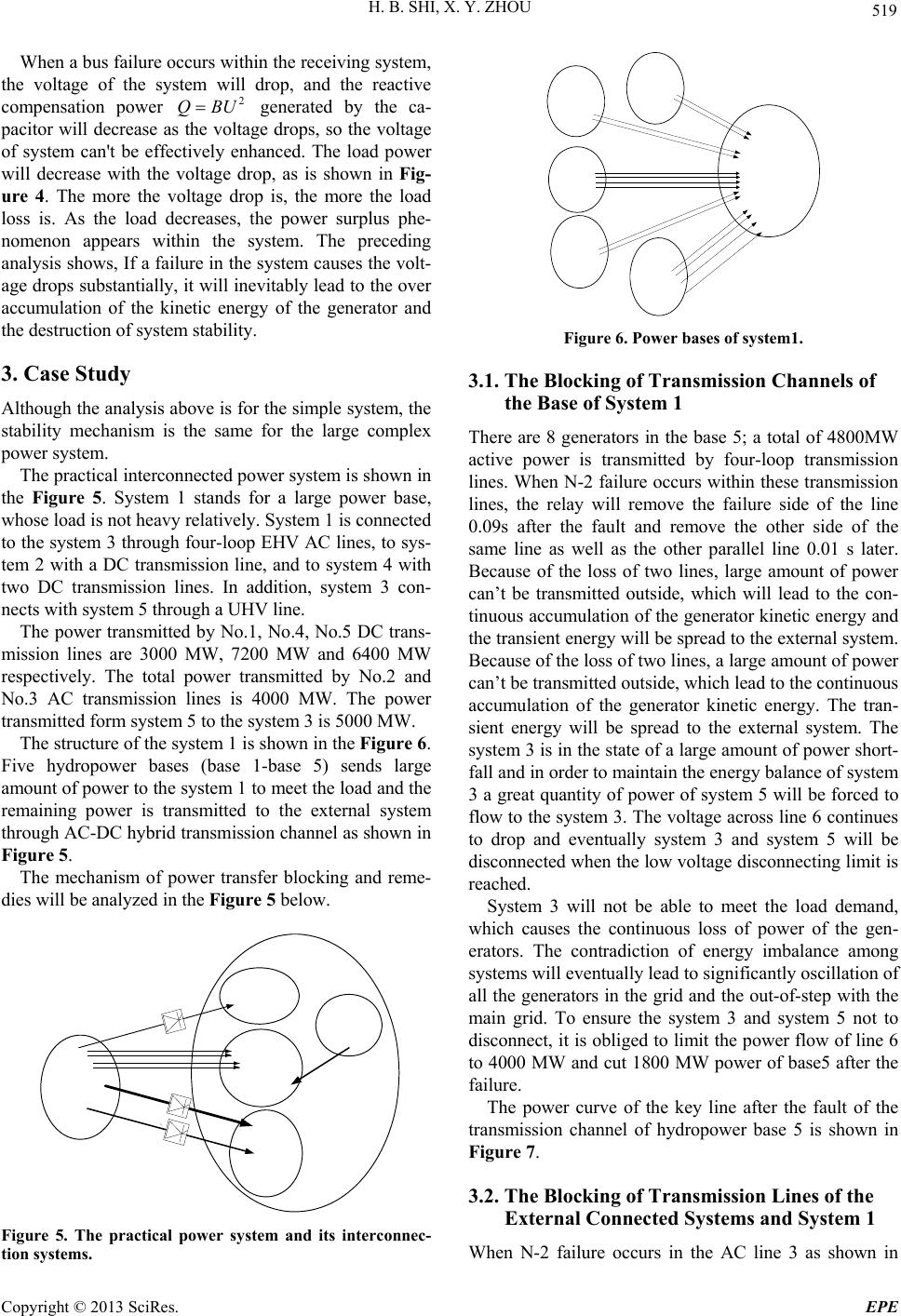 H. B. SHI, X. Y. ZHOU 519 When a bus failure occurs within the receiving system, the voltage of the system will drop, and the reactive compensation power generated by the ca- pacitor will decrease as the voltage drops, so the voltage of system can't be effectively enhanced. The load power will decrease with the voltage drop, as is shown in Fig- ure 4. The more the voltage drop is, the more the load loss is. As the load decreases, the power surplus phe- nomenon appears within the system. The preceding analysis shows, If a failure in the system causes the volt- age drops substantially, it will inevitably lead to the over accumulation of the kinetic energy of the generator and the destruction of system stability. 2 QBU 3. Case Study Although the analysis abov e is for the simple system, the stability mechanism is the same for the large complex power system. The practical interconnected power system is shown in the Figure 5. System 1 stands for a large power base, whose load is not heavy relatively. System 1 is connected to the system 3 through four- loop EHV AC lines, to sys- tem 2 with a DC transmission line, and to system 4 with two DC transmission lines. In addition, system 3 con- nects with system 5 through a UHV line. The power transmitted by No.1, No.4, No.5 DC trans- mission lines are 3000 MW, 7200 MW and 6400 MW respectively. The total power transmitted by No.2 and No.3 AC transmission lines is 4000 MW. The power transmitted form system 5 to the system 3 is 5000 MW. The structure of the system 1 is shown in the Figure 6. Five hydropower bases (base 1-base 5) sends large amount of power to the system 1 to meet the load and the remaining power is transmitted to the external system through AC-DC hybrid tr ansmission channel as shown in Figure 5. The mechanism of power transfer blocking and reme- dies will be analyzed in the Figure 5 belo w. Figure 5. The practical power system and its interconnec- tion systems. Figure 6. Power bases of system1. 3.1. The Blocking of Transmission Channels of the Base of System 1 There are 8 generators in the base 5; a total of 4800MW active power is transmitted by four-loop transmission lines. When N-2 failure occurs within these transmission lines, the relay will remove the failure side of the line 0.09s after the fault and remove the other side of the same line as well as the other parallel line 0.01 s later. Because of the loss of two lines, large amount of power can’t be transmitted outside, which will lead to the con- tinuous accumulation of the generator kinetic energy and the transient energy will be spread to the external system. Because of the loss of two lines, a large amount of power can’t be transmitted outside, which lead to the continuous accumulation of the generator kinetic energy. The tran- sient energy will be spread to the external system. The system 3 is in the state of a large amount of power short- fall and in order to maintain the energy balance of system 3 a great quantity of power of system 5 will be forced to flow to the system 3. The voltage across line 6 continues to drop and eventually system 3 and system 5 will be disconnected when the low voltage disconnecting limit is reached. System 3 will not be able to meet the load demand, which causes the continuous loss of power of the gen- erators. The contradiction of energy imbalance among systems will eventually lead to significantly oscillation of all the generators in the grid and the out-of-step with the main grid. To ensure the system 3 and system 5 not to disconnect, it is obliged to limit the power flow of line 6 to 4000 MW an d cut 1800 MW power of b ase5 after the failure. The power curve of the key line after the fault of the transmission channel of hydropower base 5 is shown in Figure 7. 3.2. The Blocking of Transmission Lines of the External Connected Systems and System 1 When N-2 failure occurs in the AC line 3 as shown in Copyright © 2013 SciRes. EPE 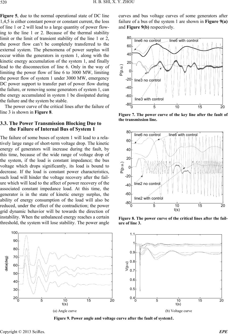 H. B. SHI, X. Y. ZHOU Copyright © 2013 SciRes. EPE 520 Figure 5, due to the normal operational state of DC line 1,4,5 is either constant power or constant current, the loss of line 1 or 2 will lead to a large quantity of power flow- ing to the line 1 or 2. Because of the thermal stability limit or the limit of transient stability of the line 1 or 2, the power flow can’t be completely transferred to the external system. The phenomena of power surplus will occur within the generators in system 1, along with the kinetic energy accumulation of the system 1, and finally lead to the disconnection of line 6. Only in the way of limiting the power flow of line 6 to 3000 MW, limiting the power flow of system 1 under 3000 MW, emergency DC power support to transfer part of power flow during the failure, or removing some generators of system 1, can the energy accumulated in system 1 be dissipated during the failure and the system be stable. curves and bus voltage curves of some generators after failure of a bus of the system 1 are shown in Figure 9(a) and Figure 9(b) respectively. 05 10 15 20 -80 -60 -40 -20 0 20 40 60 80 P(p.u.) line3 no control line3 with c ontrol line6 with con trolline6 no control The power curve of the critical lines after the failure of line 3 is shown in Figure 8. Figure 7. The power curve of the key line after the fault of the transmission line. 3.3. The Power Transmission Blocking Due to the Failure of Internal Bus of System 1 05 10 15 20 -80 -60 -40 -20 0 20 40 60 80 t(s) P(p.u.) line6 with control line2 no control line6 no control line2 with cont rol The failure of some buses of system 1 will lead to a rela- tively large range of short-term voltage drop. The kinetic energy of generators will increase during the fault, by this time, because of the wide range of voltage drop of the system, if the load is constant impedance; the bus voltage which drops significantly, its load is bound to decrease. If the load is constant power characteristics, such load will hinder the voltage recovery after the fail- ure which will lead to the affect of power recovery of the associated constant impedance load. At this time, the generator is in the state of kinetic energy surplus, the ability of energy consumption of the load will also be reduced, under the effect of the contradiction; the power grid dynamic behavior will be towards the direction of instability. When the unbalanced energy reaches a certain threshold, the system will lose stability. The power angle Figure 8. The power curve of the critical lines after the fail- ure of line 3. 05 10 15 20 20 30 40 50 60 70 80 90 100 t(s) deta(deg) 05 10 15 2 0 0.4 0.5 0.6 0.7 0.8 0.9 1 1.1 t(s) V(p.u) (a) Angle curve (b) Voltage curve Figure 9. Power angle and voltage curve after the fault of system1.  H. B. SHI, X. Y. ZHOU 521 As can be seen from Figure 9, the power angles of generators oscillate obviously after the fault, the transient kinetic energy accumulated is relatively large and the voltage drop of certain bus is relatively obvious. Al- though the system is still stable during this failure, the energy balance will be severely affected from the analy- sis of section 2. If the kinetic energy of the generator excessively accumulated, excessive voltage drop will lead to the excessive load drop and the loss stability of the system. 4. Conclusions In this paper, the stability of power system with massive energy output is analyzed with viewpoint of energy bal- ance. The stability of the power system after the blocking of the output hydropower transmission lines of the inner system and the external transmission lines is studied based on the practical power system and its intercon- nected systems. The study found that power blocking and the restriction of power transmitted by the power system with massive output energy are mainly due to the stabil- ity issue of the power system with massive energy output and the operation mode of its connected power systems. To guarantee the stability of the interconnected system, the “stopgap strategy” is to limit the power flow and strengthen the security control, while the fundamental strategy is to strengthen the grid structure and construc- tion of the power transmission lines. 5. Acknowledgements This paper is sponsored by Sichuan electric power cor- poration, China on project (12H0959). REFERENCES [1] W. M. Mao, M. Hou and G. Y. Li, “Multi-Period Power Transmission Congestion Management Considering In- terruptible Loads,” Power System Technology, Vol. 32, No. 4, 2008, pp. 73-77. [2] W. E. Lv and X. C. Jiang, “Impacts of Congestion and Market Power on Market Outcomes in Competitive Elec- tricity Market,” Proceedings of the CSEE, Vol. 27, No. 28, 2007, pp. 66-73. [3] M. Pai and A. Energy, “Function Analysis for Power System Stability,”1989. [4] X. H. Qin, Y. T. Song and L. Zhao, “Comparative Re- search on Grid-Connection Modes for Huge Power Sup- plies,” Power System Technology, Vol. 33, No. 17, 2009, pp. 64-69. [5] P. Kunder, “Power System Stability and Control,” New York: McGraw-Hill Inc, 1994. [6] H. J. Li, Y. Tang and X. M. Li, “Analysis of the Typical Schemes for Security and Stability Control Systems of Electric Power Transmission and the Devices’ Main and Auxiliary op Eration Configuration Principles,” Power System Protection and Control, Vol. 39, No. 4, 2011, pp. 141-145. Copyright © 2013 SciRes. EPE |