 International Journal of Medical Physics, Clinical Engineering and Radiation Oncology, 2013, 2, 117-124 Published Online November 2013 (http://www.scirp.org/journal/ijmpcero) http://dx.doi.org/10.4236/ijmpcero.2013.24016 Open Access IJMPCERO The Reproducibility of Patient Setup for Head and Neck Cancers Treated with Image-Guided and Intensity-Modulated Radiation Therapies Using Thermoplastic Immobilization Device Akihiro Nakata1,2, Kunihiko Tateoka1,3*, Kazunori Fujimoto1,4, Yuichi Saito1, Takuya Nakazawa1, Tadanori Abe1, Masaki Yano1, Koichi Sakata1,3 1Department of Medical Physics, Graduate School of Medicine, Sapporo Medical University, Sapporo, Japan 2Nikko Memorial Hospital, Muroran, Japan 3Department of Radiology, Sapporo Medical University, Sapporo, Japan 4Radiation Therapy Research Institute, Social Medical Corporation Teishinkai, Sapporo, Japan Email: *tateoka@sapmed.ac.jp Received July 30, 2013; revised August 25, 2013; accepted September 10, 2013 Copyright © 2013 Akihiro Nakata et al. This is an open access article distributed under the Creative Commons Attribution License, which permits unrestricted use, distribution, and reproduction in any medium, provided the original work is properly cited. ABSTRACT The reproducibility of patient setup is an important issue for head and neck cancers treated with intensity-modulated radiation therapy (IMRT). In this study, an image-guided radiation therapy (IGRT) system has been used to minimize the uncertainty of patient setup while standard thermoplastic masks were used to provide adequate immobilization for the head and neck. However, they do not provide sufficient immobilization of the shoulders, which is an important re- quirement in comprehensive nodal irradiation. Therefore, we investigated the setup and rotational shifts in head and neck cancer patients undergoing IMRT for which this immobilization device had been used together with an IGRT sys- tem. The setup and rotational shifts of patients were analyzed using the ExacTrac X-ray 6D IGRT system. The patients were classified as having head and neck tumors in the upper or lower regions. The upper neck nodes included lymph nodal level II while the lower neck nodes included lymph nodal levels III and IV. Clinical data from 227 treatment ses- sions of 12 head and neck cancer patients were analyzed. The random translational error in inter- and intra-fraction er- rors of the anterio-posterior (AP) direction might influence the rotational errors of pitch and roll in the upper region. At the same time, the random translational error in the inter- and intra-fraction errors of the AP direction might influence the rotational error of roll in the lower region. We believe that these random translational errors should be considered during treatment. We found variability in random translational errors for different regions in the anatomy of head and neck cancer patients due to rotational shifts. Depending on the location of the primary lesion or the selected nodal treatment targets, these relative positional variations should be considered when setup and rotational shifts are corrected with IGRT systems before treatment. Keywords: IMRT; IGRT; Radiation Therapy; Immobilization; Head and Neck Cancer 1. Introduction The primary goal of radiation therapy is to deliver the desired radiation dose accurately to the desired target volume throughout the course of treatment. Technologi- cal advances in conformal radiation therapy have made it possible to tailor treatment to match the shape and posi- tion of the target, and thereby minimizing normal tissue damage to a greater extent than previously possible. One technique, intensity-modulated radiation therapy (IMRT), has yielded significant gains in tumor control and toxic- ity reduction [1-3]. Another technique, image-guided radiation therapy (IGRT), has focused on the characteri- zation and control of patient movement, organ motion, and anatomical deformation, which introduce geometric uncertainty and limit the effectiveness of high-precision treatment. Target localization performed with appropriate tech- nologies and frequency is a critical component of treat- *Corresponding author.  A. NAKATA ET AL. Open Access IJMPCERO 118 ment quality assurance. For example, the target position relative to the beams has been inferred from surface marks on the patient’s skin or through an immobilization device and verified using megavoltage radiographs of the treatment portal. With IGRT, imaging technology has made it possible to image soft tissue volumes and bones using x-rays (kV) in the treatment setting. Enhancing localization practices reduces treatment errors, permits the monitoring of anatomical changes, and minimizes un- certainties that could influence clinical outcomes [4]. Analysis of the reproducibility of patient setup is an important issue for radiation treatments employing IMRT and IGRT. In particular, the standard thermoplastic mask provides adequate immobilization of the head and neck. However, it fails to provide sufficient immobilization of the shoulders which is an important requirement when IMRT and IGRT systems are used for comprehensive nodal irradiation [5,6]. In Engelsman et al. [7] investigation of the intra-frac- tion patient motion before IMRT treatment of the head and neck, it was found that translational motion of less than 1 mm is possible, depending on the characteristics of the immobilization device used. However, they re- ported a limitation in determining the accuracy of patient setup, since their method only implemented two-dimen- sional (2D)/2D matching using 2D portal images and 2D digitally reconstructed radiographs (DRRs) [5,6,8]. There is an important flaw in this technique because it is not always possible to distinguish mismatches due to transla- tional shifts from these images due to rotational dis- placements. Inter-fraction motion before IMRT treatment of the head and neck analyzed through 2D/2D matching of portal images and DRRs is also discussed in other literatures [9,10]. Zhang et al. [6] investigated inter-fraction patient mo- tion as the deviations between the daily computed tomo- graphy (CT) and the planning CT of a region of interest with respect to a reference point, as determined by three radiopaque markers on the thermoplastic mask before IMRT treatment of the head and neck. Inter-fraction pa- tient motions, including translations and rotations, for three individual bony landmarks in the head and neck region were separately registered in the daily CTs with respect to their positions in the reference planning CT. The study quantified inter-fraction patient motions in a three-dimensional (3D) manner, but they did not report intra-fraction patient motions. With the recent availabil- ity of IGRT systems, it is possible to correct the patient setup error just before treatment and/or before the deliv- ery of each IMRT field with the patient immobilized in the treatment position. Data on the intra-factional motion of patients under specific immobilization methods will provide a measure of the reproducibility of patient setup when these devices are used. Additionally, the range of inter-fractional motion of individual treatment sites will provide an important data in order to set acceptable tol- erances when these devices are used. The aim of this study was to evaluate the reproducibility of patient setup for head and neck cancers treated with image-guided IMRT using thermoplastic immobilization device. 2. Materials and Methods 2.1. IGRT System Step-and-shoot IMRT beams having five segments Inter- and intra-fraction patient motions were analyzed using the ExacTrac x-ray 6D IGRT systems (BrainLAB AG, Feldkirchen, Germany) with system software version 3.5. The ExacTrac x-ray 6D system consists of infrared (IR) tracking and x-ray components. The infrared tracking component includes two IR cameras, passive IR reflect- ing spheres placed on the patient or the immobilization device, and a plastic mask molded to the patient’s con- tour. The IR cameras are rigidly mounted to the ceiling, and they emit a low IR signal that is reflected and ana- lyzed for positional information. Patient setup can then be easily achieved by moving the couch to match the marker’s position with those recorded in a CT image. The software also provides rotational offsets along three primary axes. The external markers must be positioned in a relatively stable location to achieve accurate setup. The x-ray component consists of two floor-mounted kV x-ray tubes that project in an oblique angle medially, anteriorly, and inferiorly onto two corresponding amorphous silicon flat panel detectors mounted on the ceiling (Figure 1). Two stereoscopic images produced by the two kV x-ray tubes are obtained after the patient is initially set up with the ExacTrac (infrared) system. These images are then compared with the corresponding isocenter of each patient’s 3D CT simulation images in the form of DRRs. The software provides several options for matching the images. One of the methods is the six degrees of freedom (6D) fusion method assume that the patient is set up with rotational offsets. Corresponding DRRs are generated at fixed angles, and position adjustment in three transla- tional and three rotational directions (6D) is performed on the DRRs to best match the x-ray images. The soft- ware then compares these DRRs with the corresponding x-ray images to obtain the set of DRRs with maximal similarity to the corresponding x-ray images. The best match is thus determined, and the three translational and three rotational position variations used to generate the set of DRRs are the 6D offsets used to fuse the images. Jian et al. demonstrated in a phantom study that the maximal random error of this system was ±0.6 mm in each direction with 95% confidence interval while sys- tematic error of approximately 0.4mm was found in the  A. NAKATA ET AL. Open Access IJMPCERO 119 Figure 1. (a) The ExacTrac X-ray 6D IGRT systems showing the infrared camera, flat panel, and kV tube; (b) Head, neck and shoulder thermoplastic immobilization system (S-Type, Medtec, Orange City, IA) and plastic mask. longitudinal direction [11]. Vertical, longitudinal, and la- teral displacements of the table as well as couch angles (roll, pitch, and yaw) are calculated by the system to correct for the differences in the actual patient setup and the patient setup when the reference CT was taken. The entire imaging, analysis, and patient shift require 3 to 5 min of additional setup time than that needed for patients undergoing no image guidance [8,12]. 2.2. Analysis of Patient Motions Twelve patients with head and neck cancers treated with IMRT were selected for this study. Their planning CT was taken at a spatial resolution of 0.94 mm per pixel in the transverse plane, and the slice thickness was 1 mm. Before beam delivery they patient images were also ta- ken with the ExacTrac x-ray 6D IGRT systems, of which 227 pairs of stereoscopic images were used for the study. Head and neck IMRT patients are immobilized at our institution by using a head-neck-shoulder thermoplastic immobilization system (S-Type, Medtec, Orange City, IA) with patient-specific neck cushions. IMRT treat- ments were performed using 6MV x-rays from a Sie- mens Mevatron Primus (Siemens, Munich, Germany) with 80 leaf pairs of 1 cm projected width at the iso- center. For head and neck IMRT patients, we use a generic isocenter, which is typically located around the C2 to C4 vertebrae. Although individual bony structures are rigid, bony structures in the head and neck region collectively, are not simple rigid objects. Zhang et al. [6] reported that regions of interest (ROIs) in different locations in the head and neck region were needed to analyze patient motion. Patient motions were analyzed by separating the head and neck cancers into two ROIs for nasopharyngeal, oropharyngeal, and hypopharyngeal cancers. The first region was comprised of the primary tumor and upper neck nodes (upper region, close to the clivus and C3 ver- tebra (C3) regions). The upper neck nodes included lymph nodal level II of the neck. The second region was comprised of the lower neck nodes (lower region, close to the C5 vertebra (C5) and supraclavicular regions). The lower neck nodes included lymph nodal levels III and IV of the neck. The clivus to C3 region represents the tumor to subclinical disease for head and cancer patients. The C5 to supraclavicular region represents the supraclavicu- lar lymph nodes that are occasionally treated with IMRT. Therefore, to analyze the set-up reproducibility of head and neck cancers, the region of interest was separated into upper region and lower region. All patient setup were performed with aid of the Ex- acTrac system. The necessary shifts to move the patient to the isocenter were acquired with the position of the infrared markers placed on top of the thermoplastics used as bases for patient set-up localization. Stereoscopic x- ray images from two directions were taken. In the analy- sis of the upper region, the lower region of the images was masked using the system software. Likewise, in the analysis of the lower region, the upper regions in the stereoscopic images were masked as shown in Figure 2. The images were automatically registered to the DRR generated from the planning CT image set. The ExacTrac system software then computed the shifts necessary to move the patient to the calculated isocenter for upper and lower regions respectively. These were defined as the pretreatment shifts. The couch was adjusted when the computed translational and rotational shifts were more than 1.0 mm and 1.0 degree, respectively (the mean shift is about 1 mm according to rotational error of one degree in this study). When the computed translational and rotational shifts for the upper and lower regions were in opposite direc- tions, the patient had to be repositioned in the thermo- plastic mask and stereoscopic images were re-taken to re- calculate the pre-treatment shifts. Another set of stereo- scopic images was taken after the completion of every fraction of treatment in order to obtain the post-treatment shifts.Inter-fractional motion, both in translational and rotational directions, was determined from all the pre- treatment shifts. On the other hand, intra-fractional mo-  A. NAKATA ET AL. Open Access IJMPCERO 120 (a) (b) Figure 2. Two verification kV x-ray images for evaluating the localization accuracy, which is determined by measuring the distance of isocenter between the x-ray system and the treatment for the upper region (a) and lower region (b). The dark gray region not fused image is masked. tion, both in the translational and rotational directions, was derived from the pre- and post-treatment shifts ob- tained within the same day (or treatment fraction). The translational shifts were calculated along the anterio- posterior (AP), cranio-caudal (CC) and left-light (LR) directions while the rotational shifts in roll, pitch and yaw directions. The mean error ( ), systematic error (∑), and random error (δ) for the inter- and intra-frac- tional motions were defined as the mean of the variation inter- or intra-fractional motion of the entire patients, the standard deviation of inter- or intra-fractional motion of patient-to-patient, and the mean of the observed random standard deviations of the entire patients in the study, respectively [13]. 3. Results 3.1. The Mean Translational and Rotational Errors (upper trans X,upper rot X), Systematic Errors (upper trans ,upper rot ), and Random Errors (upper trans ,upper rot ) for the Upper Region The translational errors are given in Table 1, which quan- titatively summarizes the pre-treatment (Before), post- treatment (After), and intra-translation (Intra) mean upper trans X, systematic upper trans , and random errors upper trans (mm) and their ranges in the LR, CC, and AP directions for the upper region of the patient population. Table 1 shows that the translational mean and system- atic error of the upper region before treatment of the en- tire patient population (12 patients) were small (less than 0.26 mm) in all directions, indicating that there was no significant systematic error between the treatment simu- lation and the actual treatment. In the LR and CC direc- tions, the translational systematic errors after treatment and the intra-fraction error were consistent (less than 0.59 mm) with the pre-treatment values; however, that of the AP direction was slightly larger, with a range of 1.02 to 1.22 mm. Moreover, the pre-treatment, post-treatment, and intra-fraction random translational errors exhibited ranges of 0.65 to 0.76 mm in the CC direction and 0.83 to 2.04 mm in the AP and LR directions. The rotational errors are given in Table 2, which quan- titatively summarizes the pre-treatment (Before), post- treatment (After), and intra-fraction (Intra) upper rot X, sys- tematic upper rot , and random errors upper rot (degree) and their ranges in the roll, pitch and yaw directions for the upper region of the patient population. Table 2 shows that the range of the pre-treatment, post-treatment, and intra-fractionation mean rotational, rotational systematic and random rotational errors was −0.69 to 1.04 degree in the yaw and pitch directions; therefore, the effect of the roll and yaw directions was small. The range of the mean rotational error was consis- tent in all three directions, but the ranges of the rotational systematic and random rotational errors were larger in the pitch direction than in the roll and yaw directions. That is, the rotational errors for the upper regions were small in all directions excluding the post-treatment and inter-fraction rotational systematic and random errors in the roll direction. The systematic and random errors of translation and rotation for the upper region in all direc- tions exhibited approximately normal probability distri- butions. 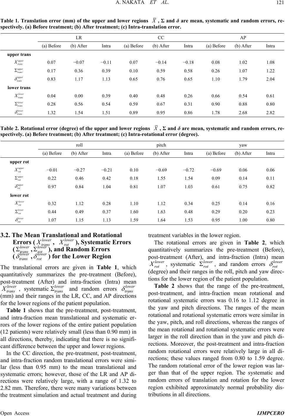 A. NAKATA ET AL. Open Access IJMPCERO 121 Table 1. Translation error (mm) of the upper and lower regions , Σ and δ are mean, systematic and random errors, re- spectively. (a) Before treatment; (b) After treatment; (c) Intra-translation error. LR CC AP (a) Before (b) After Intra (a) Before(b) After Intra (a) Before (b) After Intra upper trans upper trans X 0.07 −0.07 −0.11 0.07 −0.14 −0.18 0.08 1.02 1.08 upper trans 0.17 0.36 0.39 0.10 0.59 0.58 0.26 1.07 1.22 upper trans 0.83 1.17 1.13 0.65 0.76 0.65 1.10 1.79 2.04 lower trans lower trans X 0.04 0.00 0.39 0.40 0.48 0.26 0.66 0.54 0.61 lower trans 0.28 0.56 0.54 0.59 0.67 0.31 0.90 0.88 0.80 lower trans 1.32 1.54 1.51 0.89 0.95 0.86 1.78 2.68 2.82 Table 2. Rotational error (degree) of the upper and lower regions , Σ and δ are mean, systematic and random errors, re- spectively. (a) Before treatment; (b) After treatment; (c) Intra-rotational error (degree). roll pitch yaw (a) Before (b) After Intra (a) Before(b) After Intra (a) Before (b) After Intra upper rot upper rot X −0.01 −0.27 −0.21 0.10 −0.69 −0.72 −0.69 0.06 0.06 upper rot 0.22 0.46 0.42 0.18 1.55 1.54 0.09 0.14 0.11 upper rot 0.97 0.84 1.04 0.81 1.07 1.03 0.61 0.75 0.82 lower rot lower rot X 0.32 1.12 0.28 1.10 1.12 0.34 0.25 0.14 0.16 lower rot 0.44 0.49 0.37 1.60 1.63 0.48 0.29 0.20 0.23 lower rot 1.07 1.15 1.13 1.59 1.64 1.53 0.95 1.00 0.80 3.2. The Mean Translational and Rotational Errors (lower trans X, lower rot X), Systematic Errors (lower trans ,lower rot ), and Random Errors (lower trans ,lower rot ) for the Lower Region The translational errors are given in Table 1, which quantitatively summarizes the pre-treatment (Before), post-treatment (After) and intra-fraction (Intra) mean lower trans X, systematiclower trans and random errors lower trans (mm) and their ranges in the LR, CC, and AP directions for the lower regions of the patient population. Table 1 shows that the pre-treatment, post-treatment, and intra-fraction mean translational and systematic er- rors of the lower regions of the entire patient population (12 patients) were relatively small (less than 0.90 mm) in all directions, thereby, indicating that there is no signifi- cant difference between the upper and lower regions. In the CC direction, the pre-treatment, post-treatment, and intra-fraction random translational errors were simi- lar (less than 0.95 mm) to the mean translational and systematic errors; however, those of the LR and AP di- rections were relatively large, with a range of 1.32 to 2.82 mm. Therefore, there were many variations between the treatment simulation and actual treatment and during treatment variables in the lower region. The rotational errors are given in Table 2, which quantitatively summarizes the pre-treatment (Before), post-treatment (After), and intra-fraction (Intra) mean lower rot X, systematic lower rot , and random errors lower rot (degree) and their ranges in the roll, pitch and yaw direc- tions for the lower region of the patient population. Table 2 shows that the range of the pre-treatment, post-treatment, and intra-fraction mean rotational and rotational systematic errors was 0.16 to 1.12 degree in the yaw and pitch directions. The ranges of the mean rotational and rotational systematic errors were similar in the yaw, pitch, and roll directions, whereas the ranges of the mean rotational and rotational systematic errors were larger in the roll direction than in the yaw and pitch di- rections. Moreover, the post-treatment and intra-fraction random rotational errors were relatively large in all di- rections; these values ranged from 0.80 to 1.59 degree. The random rotational error of the lower region was lar- ger than that of the upper region. The systematic and random errors of translation and rotation for the lower region exhibited approximately normal probability dis- tributions in all directions.  A. NAKATA ET AL. Open Access IJMPCERO 122 4. Discussion In this study, we investigated the setup reproducibility in head and neck cancer therapy for two different regions using from ExacTrac X-ray 6D IGRT data acquired while patients were immobilized in the treatment posi- tion. Recent work by Court et al. [5] and Zhang et al. [6] in- dicated that bony landmarks C2, C6, and the palatine process of maxilla (PPM) were independently chosen as alignment targets to represent these landmarks in most head and neck cancer patients. In this way, bony struc- tures are used as landmarks for alignment in head and neck cancer patients. For this reason, it was assumed that the position of targets or avoidance structures relative to bony landmarks is consistent between fractions for head and neck cancer patients [5,6]. However, it may be diffi- cult to concurrently correct patient setup errors of upper region and lower region using these three landmarks in- dependently. Our landmarks for patient motions were analyzed by separating the head and neck cancers into two ROIs; the first region included the primary tumor + upper neck nodes (upper region, close to the clivus and the C3 ver- tebra (C3) region), whereas the second region included the lower neck nodes (lower region, close to the C5 ver- tebra (C5) region and the supraclavicular region). In par- ticular, the upper region (the clivus to C3 region) repre- sents the subclinical representation of the tumor for na- sopharyngeal, oropharyngeal, and hypopharyngeal can- cers. Zhang et al [6] reported that the range of motion in the translational direction of the bony landmarks C3, C6 and PPM were generally between −0.5 cm to 0.5 cm at a 90% confidence interval. The range of motion was slightly worse for C6 in the LR direction at −0.68 cm to 0.62cm and for the PPM in the CC direction at −0.5 cm to 1.15 cm. They reported no significant difference when using the S-board or conventional facemask. Moreover, after C2 alignment using IGRT, they reported a 90% confi- dence range of −5.4 to 3.3 mm for C6 in each direction and −7.5 to 9.0 mm for PPM in each direction. The re- sults of Court et al. [5] were similar to those of Zhang et al. Therefore, they described that some patients exhibit large uncertainties in the C6 or supraclavicular region that were useful for evaluating patient setup shifts. More- over, they described that the lack of significant shoulder shifts in the first week of treatment does not necessarily indicate that few/no shoulder shifts will be observed later during treatment because one patient had no shoulder shifts larger than 5 mm until the 32nd fraction but had large shifts for every fraction thereafter (total treatment, 35 fractions) and other patients had large shifts from the start of treatment. The method of correcting patient setup errors for the lower region is to treat the lower region using a conventional anterior field. However, Thorstad et al. [14] indicated that a cold match line between conven- tional and IMRT fields can be a significant cause of re- currences when implemented to treat the lower region using a conventional anterior field. For that reason, plan- ning target volume (PTV) margins are a geometric con- cept defined to ensure that, in the presence of setup and other uncertainties, the prescribed dose is actually deliv- ered to the clinical target volume (CTV) is not difficult to define using the published formulations for calculating the necessary PTV basis of normal probability distribu- tion for patient setup error [15-17]. Therefore, a correc- tion method for head and neck cancer patients described online re-planning to correct all shifts and rotations in different regions or physically repositioning the patient in the mask [5,6]. These reports are critical when treatment is given using IGRT systems to be able to reposition the patient. In our IGRT assisted evaluation of the mean transla- tional and systematic errors, the range of motion of the upper and lower regions of head and neck cancer patients were about 1 mm which was consistent with the other published results [5,6]. Our patient setup error data ex- hibited an approximately normal probability distribution. The random translational error was larger than the mean translational and systematic errors for the upper and lower regions of head and neck cancer patients in all directions. This is because the translational error in the AP direction strongly influences the pitch and rolls rota- tions. The pitch and roll rotations are more associated with the translational error in the CC and LR directions, respectively, and yaw rotation is determined by the trans- lational error in the LR and CC directions. Although it appears that large rotational errors were observed in all directions, the effects of these three rotations indicated that the effect of random translational error was larger than those of mean and systematic translational errors (Tables 1 and 2); the mean and systematic rotational errors were slightly influenced by the mean and system- atic translational errors in the all directions. Therefore, the post-treatment and intra-fraction translational errors in the AP direction influence the rotational errors of pitch and roll in the upper region. At the same time, the post- treatment and intra-fraction translational errors in the AP direction influence the rotational error of roll in the lower region. For this reason, even if head and neck cancer patients were treated with IGRT and immobilization de- vice, they do not provide sufficient reproducibility of patient setup for head and neck region, which is an im- portant requirement in comprehensive nodal irradiation. We believe that these random translational errors should be considered in the course of treatment. Our use of IGRT is straightforward and only adds approximately 5 min to the delivery of each fraction. In addition, global population data might permit the creation of a class solu-  A. NAKATA ET AL. Open Access IJMPCERO 123 tion to calculate PTV margins. 5. Conclusions In this study, we used the ExacTrac X-ray 6D IGRT sys- tem and two regions (the upper and lower region) analy- sis method to quantify the intra-fractionation error for patient setup with head and neck cancer patients who underwent fractionated external beam radiotherapy using a commercially available immobilization device. Setup and rotational shifts in the upper and lower re- gion for the head and neck cancer patients were analyzed. We found variability in random translational errors for different regions of the anatomy in the head and neck cancer patient as a consequence of rotational shifts. De- pending on the location of the primary lesion or the se- lected nodal treatment targets, these relative positional variations should be considered when setup and rota- tional shifts are corrected with IGRT system and immo- bilization device before treatment. 6. Acknowledgements The author(s) expresses their appreciation to Prof. Jun Takada (Radiation Protection Laboratory, Sapporo Medi- cal University) for his support and insightful comments regarding this study. We likewise acknowledge the con- tributions to this work by Dr. Kenichi Tanaka (Radiation Protection Laboratory, Sapporo Medical University), Dr. Kenichi Kamo (Mathematics and Information Sciences, Sapporo Medical University). REFERENCES [1] M. J. Zelefskya, Z. Fuksa, L. Happersettb, H. J. Lee, C. C. Ling, C. M. Buman, M. Hunt, T. Wolfe, E. S. Venkatra- man, A. Jackson, M. Skwarchuk and S. A. Leibel, “Cli- nical Experience with Intensity Modulated Radiation Therapy (IMRT) in Prostate Cancer,” Radiotherapy and Oncology, Vol. 55, No. 3, 2000, pp. 241-249. http://dx.doi.org/10.1016/S0167-8140(99)00100-0 [2] A. Pirzkall, F. Lohr, A. Hoss, M. Wannenmacher, J. De- bus and M. Carol, “Comparison of Intensity-Modulated Radiotherapy with Conventional Conformal Radiotherapy for Complex-Shaped Tumors,” International Journal of Radiation Oncology, Biology, Physics, Vol. 48, No. 5, 2000, pp. 1371-1380. http://dx.doi.org/10.1016/S0360-3016(00)00772-0 [3] S. Tribius and C. Bergelt, “Intensity-Modulated Radio- therapy versus Conventional and 3D Conformal Radio- therapy in Patients with Head and Neck Cancer: Is There a Worthwhile Quality of Life Gain?” Cancer Treatment Reviews, Vol. 37, No. 7, 2011, pp. 511-519. http://dx.doi.org/10.1016/j.ctrv.2011.01.004 [4] B. Tomas, S. Rupert, N. Wilfried and D. E. Wazer, “Im- age-Guided IMRT,” Springer Verlag-Heidelberg, Berlin, 2006. [5] L. E. Court, L. Wolfsberger, A. M. Allen, S. James and R. B. Tishler, “Clinical Experience of the Importance of Daily Portal Imaging for Head and Neck IMRT Treat- ments,” Journal of Applied Clinical Medical Physics, Vol. 9, No. 3, 2008, p. 2756. http://dx.doi.org/10.1120/jacmp.v9i3.2756 [6] L. Zhang, A. S. Garden, J. Lo, K. K. Ang, A. Ahamad, W. H. Morrison, D. Rosenthal, M. S. Chambers, X. R. Zhu, R. Mohan and L. Dong, “Multiple Region-of-Interest Analysis of Setup Uncertainties in Head-and-Neck Radiotherapy,” International Journal of Radiation Oncology, Biology, Physics, Vol. 64, No. 5, 2006, pp. 1559-1569. http://dx.doi.org/10.1016/j.ijrobp.2005.12.023 [7] M. Engelsman, S. J. Rosenthal, S. L. Michaud, J. A. Adams, R. J. Schneider, S. G. Bradley, J. B. Flanz and H. M. Kooy, “Intra- and Interfractional Patient Motion for a Variety of Immobilization Devices,” Medical Physics, Vol. 32, No. 11, 2005, pp. 3468-3474. http://dx.doi.org/10.1118/1.2089507 [8] J.-Y. Jin, F.-F. Yin, S. E. Tenn, P. M. Medin and T. D. Solberg, “Use of the Brainlabexactrac X-Rays 6D System in Image-Guided Radiotherapy,” Medical Dosimetry, Vol. 33, No. 2, 2008, pp. 124-134. http://dx.doi.org/10.1016/j.meddos.2008.02.005 [9] A. Bel, R. Keus, R. Vijlbrief and J. V. Lebesque, “Set up Deviations in Wedged Pair Irradiation of Parotid Gland and Tonsillar Tumors Measured with an Electronic Portal Imaging Device,” Radiotherapy and Oncology, Vol. 37, No. 2, 1995, pp. 153-159. http://dx.doi.org/10.1016/0167-8140(95)01627-S [10] R. Marsh, J. Balter, V. L. Evans and A. Eisbruch, “De- sign and Analysis of an Immobilisation and Repositioning System for Treatment of Neck Malignancies,” Medical Dosimetry, Vol. 22, No. 4, 1997, pp. 293-297. http://dx.doi.org/10.1016/S0958-3947(97)00102-7 [11] J. Y. Jin, S. Ryu, K. Faber, T. Mikkelsen, Q. Chen, S. Li and B. Movsas, “2D/3D Image Fusion for Accurate Tar- get Localization and Evaluation of a Mask Based Stereo- tactic System in Fractionated Stereotactic Radiotherapy of Cranial Lesions,” Medical Physics, Vol. 33, No. 12, 2006, pp. 4557-4566. http://dx.doi.org/10.1118/1.2392605 [12] S. A. Arrizabalaga, L. B. Gonzalez, J. V. R. Ferrando, J. P. Peidro, D. P. Meseguer and T. G. Hemandez, “Prostate Planning Treatment Volume Margin Calculation Based on the Exactrac X-Ray 6D Image-Guided System: Mar- gins for Various Clinical Implementations,” International Journal of Radiation Oncology, Biology, Physics, Vol. 69, No. 3, 2007, pp. 936-943. http://dx.doi.org/10.1016/j.ijrobp.2007.06.063 [13] J. C. Stroom and B. J M. Heijmen, “Geometrical Uncer- tainties, Radiotherapy Planning Margins, and the ICRU- 62 Report,” Radiotherapy and Oncology, Vol. 64, No. 1, 2002, pp. 75-83. http://dx.doi.org/10.1016/S0167-8140(02)00140-8 [14] W. Thorstad, S. Hong, A. J. Hope, P. E. Lindsay, B. Haughey, J. O. Deasey and K. Chao, “Patterns of Failure in Patients Receiving Intensity Modulated Radiation The- rapy (IMRT) for Head and Neck Cancer,” International Journal of Radiation Oncology, Biology, Physics, Vol. 63,  A. NAKATA ET AL. Open Access IJMPCERO 124 2005, p. S74. http://dx.doi.org/10.1016/j.ijrobp.2005.07.127 [15] M. V. Herk, P. Remeijer, C. Rasch and J. V. Lebisque, “The Probability of Correct Target Dosage: Dose-Popu- lation Histograms for Deriving Treatment Margins in Ra- diotherapy,” International Journal of Radiation Oncology, Biology, Physics, Vol. 47, No. 4, 2000, pp. 1121-1135. http://dx.doi.org/10.1016/S0360-3016(00)00518-6 [16] E. Astreinidou, A. Bel and C. P. J. Raaijmakers, “Ade- quate Margins for Random Setup Uncertainties in Head- and-Neck IMRT,” International Journal of Radiation Oncology, Biology, Physics, Vol. 61, No. 3, 2005, pp. 938-944. http://dx.doi.org/10.1016/j.ijrobp.2004.11.016 [17] J. C. Stroom, H. C. J. de Boer, H. Huizinga and A. G. Visser, “Inclusion of Geometrical Uncertainties in Ra- diotherapy Treatment Planning by Means of Coverage Probability,” International Journal of Radiation Oncol- ogy, Biology, Physics, Vol. 43, No. 4, 1999, pp. 905-919. http://dx.doi.org/10.1016/S0360-3016(98)00468-4
|