Engineering, 2013, 5, 85-89
http://dx.doi.org/10.4236/eng.2013.510B017 Published Online October 2013 (http://www.scirp.org/journal/eng)
Copyright © 2013 SciRes. ENG
Modeling and Simulation of Lapar o scopic Tools for
Autonomously Positioning Lapar oscope in
Lapar oscopic Surgery
S. M. Megahed, A. A. Balbola
Mechanical Design & Production Engineering Department, Faculty of Engineering, Giza, Egypt
Email: smegahed@cu.edu.eg, amrbalbola@cu.edu. eg
Received December 2012
ABSTRACT
In laparoscopic surgery, the surgeons are equipped with the suitable tools for the surgery, while the laparoscope is used
to capture the operation environment and displays it on a monitor. This paper presents the mathematical kinematic posi-
tion modeling of the laparoscopic tools used for autonomous positioning of a laparoscope in such operations. These
models are obtained using Denavit-Hartenberg (D-H) Notations and Homogenous Transformation Matrix (HTM). The
laparoscopic tools are considered as six degrees of freedom (DOF) mechanisms while the laparoscope has four DOF.
The 3D loop closure equation is used to obtain the laparoscope kinematic position models in terms of those of the lapa-
roscopic tools. These models are used to simulate and align the laparoscope camera with the surgeons laparoscopic
Tools Center Points (TCP). The obtained results show the smooth positioning of the laparoscope camera for better visu-
alization of laparoscopic surgery environments.
Keywords: Laparosc opi c Surgery; Homogeno us T ransformation Matrix; Denavit-Hartenberg Notations
1. Introduction
In laparoscopic surgery, two main problems challenge
the surgeons. The first is increasing field of vision capac-
ity and controlling system to carry out complex opera-
tional gestures without using high body mobility. The
second is the tools flexibilities inside the human body to
do more complex in vivo healthcare operations. Now
most Laparoscopic Surgeries are done using 6 DOF la-
paroscopic tools to increase their flexibility inside the
human body. Surgeons visualize the surgery environment
using a laparoscope. Any wrong movement of the lapa-
roscope interrupts the operation and the surgeon stops
until controlling the laparoscope focus again on the oper-
ation area. Many researches are done for autonomously
positioning the laparoscope instead of the laparoscope
manual positioning by an operator. Halin et al. [1] de-
veloped a novel a laparoscope which detect and to follow
the movements of the surgeons head. Terry et al. [2]
built a port camera integrated with the laparoscopic tool.
Weede et al. [3] designed an endoscopic guidance system
to autonomously align the laparoscope with the TCP of
the surgeons instruments which uses the information on
the movements of the instruments from former interven-
tions to predict the laparoscope motion. Terry et al. also
[4] designed, built, and tested a novel single-port access
laparoscopic surgery specific camera system (magnet
camera). Xu et al. [5] derives the analytical solution for a
5-DOF manipulator to follow a given trajectory.
In this paper, the direct and inverse kinematic position
models of two laparoscopic tools and one laparoscope
are derived for autonomous positioning of the laparos-
cope camera. After an introduction, the paper is orga-
nized in three main sections. In Section 1, the kinematic
position models of the two 6 DOF laparoscopic tools and
one laparoscope are presented. In Section 2, the laparos-
cope models are developed as function of the parameters
of the two laparoscopic tools. The obtained simulation
results using the developed models are presented in Sec-
tion 3.
2. Kinematic Modeling of 6 DOF
Laparoscopic Tools
In laparoscopic surgery, Surgeons use two 6 DOF lapa-
roscopic tools (right & left) to carry out complex opera-
tions. The four Denavit-Hartenberg (D-H) parameters (θi,
ri, ai, and αi for i = 1, 2
6) are used for generating the
elementary HTMs (Ti,i+1) of the laparoscopic tools (see
Figure 1, and Table 1) [6].
By substituting the D-H par ameters in Ta ble 1 into (1)
the 6 elementary HTMs (Ti,i+1) for i = 1, 2
6 are de-
termined which are used in (2) to obtain the generalized
HTM (T0,7).
S. M. MEGAHED, A. A. BALBOLA
Copyright © 2013 SciRes. ENG
86
Figure 1. Laparoscopic tool kinematic diagram.
Table 1. D-H parameters.
Joint i 0 1 2 3 4 5 6
Parameter s
i
σ
- 0 0 0 1 0 0
i
θ
π
2
1
q
2
q
3
q
0
3
q
6
q
i
r
0 0 0 0
4
q
0 0
i
a
0 0 0 0 0 a5 a6
i
α
π
2
π
2
π
2
0
π
2
π
2
π
2
This generalized HTM is used with (3) representing
the desired laparoscopic tool generalized HTM (T0,7) to
obtain the expressions of the laparoscopic tool direct
kinematic position model (DKPM) and the position and
orientation of its TCP are obtained. The inverse kine-
matic position model (IKPM) is also derived using the
same generalized HTM. In the next equations S = sin and
C = cos.
Elementary HTM:
,1
0
0001
iiiiii i
iiii iii
ii i ii
CCSSCCSSSSa CC
SSCCCCCCSSa SS
TSSCC r
θθ αθαθ
θθαθαθ
αα
+


−−

=


(1)
Generalized HTM:
(2)
11 1213
21 2223
0,7 31 3233
0001
rrrn
rr rm
Trrr l



=


(3)
DKPM & IKPM: An algebraic approach is used to
calculate the laparoscopic tool DKPM and IKPM as fol-
lows:
First (2) is pre-multiplied by the inverse of the HTM
(T0,3) as presented in (4) resulting 6 Equations (5, 6, 7, 8,
9, and 10). Second (2) is pre-multiplied by the inverse of
the HTM (T0,2) and post-multiplied by the inverse of the
HTM (T6,7) as presented in (11) resulting 2 Equations (12,
13). The obtained eight equations are used to calculate
the expressions of the laparoscopic tool DKPM which
are solved to calculate its IKPM.
( )
1
0,11,2 2,30,73,4 4,55,6 6,7
TTTT TTTT
⋅⋅ ⋅⋅⋅⋅=
(4)
21131135636
rSqrCqSqCq CqCqSq−= −⋅ ⋅⋅⋅⋅
(5)
221 32135
rSqrCqSq Cq⋅⋅ ⋅−=
(6)
( )
11
63 5 63653 5
mSqn Cq
aSq CqCqCqSqaSq Cq⋅ ⋅⋅
⋅ −⋅
=+ ⋅− ⋅⋅
(7)
( )
1122 21131156
rCqSqrCqrSqSq Cq− +=⋅⋅⋅ ⋅⋅
(8)
( )
1322231 33156
rCqSqrCqrSqSq Sq−++ =⋅⋅⋅ ⋅⋅
(9)
( )
221 1
6 565 54
lCqSqm CqnSq
aSq CqaSqq
−+
=
⋅⋅⋅ ⋅
+⋅ −⋅⋅ (10)
( )
11
0,11,20,7 6,72,33,4 4,55,6
TTTT TTTT
⋅⋅⋅=⋅ ⋅⋅
(11)
( )
( )
621 131 1
6231 33135
CqrSqr Sq
SqrSqrCqSq Cq
⋅⋅ ⋅
⋅ =⋅−⋅⋅
+
(12)
( )
( )
621 131 1
6231 33135
SqrSqrSq
CqrSqrCqSq Sq
+ −=−
⋅⋅ ⋅
⋅⋅ ⋅⋅
(13)
The following is the IK PM of the 6 DOF laparoscopic
tools
2
22 22
66
12121 2223
22 2
55 5
2
1
a am
m
ar rrr
aa a

=+− −+
⋅ −⋅
(14)
( )
2
66
121 313121
22 2
55 5
22 3223 33
2
221. ...
2. 2.
aa
m
br rmrnr
aa a
rr rr

=−− −++


−+
(15)
S. M. MEGAHED, A. A. BALBOLA
Copyright © 2013 SciRes. ENG
87
2
22 22
66
13131 32 33
22 2
55 5
2
1
a an
n
cr rrr
aa a

= +−−+−

(16)
2
1 111
11
4
2
b bac
q atanatana

−± −

=

(17)
61231321
drSqr Cq⋅⋅=
(18)
62211 311
drSqrCq⋅⋅=
(19)
61321 221
cr CqrSq⋅⋅=
(20)
116 12
62 5
mSqnCqad
ca
⋅⋅ ⋅
−−
= (21 )
1
661 6261
662 6162
Cqd dc
Sqd dc
 
=
 
 
(22)
( )
6 66
2,qatanSq Cq=
(23)
61
562
d
qatan d

=


(24)
1
3 562
35 6662
0
*
Sq Cqc
CqCq CqSqd

=


(25)
( )
3 33
tan2 ,qaSq Cq=
(26)
4111
dm CqnSq⋅+⋅=
(27)
422 4141
ql CqSqdc++= −
(28)
4165655
caSq CqaSq⋅⋅ ⋅= +
(29)
( )
4263563 6
535
caCq Cq CqSqSq
a Cq Cq
= +
⋅+
⋅ ⋅⋅⋅
(30)
1
2414 41
241 42
Sqdlq c
Cqldc
−−
 
=
 
 
(3 1)
( )
3 33
tan2 ,qaSq Cq=
(32)
3. Positioning of a Robot Assisted Surgery
Laparoscope
It’s supposed that the laparoscope is always tracking the
midpoint between the TCPs of the right and left lapa-
roscopic tools. The 3D loop closure theory is used to
get the HTM of the laparoscope in terms of the left and
righ t laparoscopic tools joint angles [7]. Figures 2 and
3 present the closed loops formed by the HTM of the
right, left laparoscopic tool, and laparoscope. The prod-
uct of these HTMs is equal to a unity matrix as in (33) and
(39).
ADAB BC CD
T TTT=
(33)
Figure 2. Laparoscopic surgery environment.
Figure 3. Surgery area.
(33)(3 1)
(1 3)
01
ba ba
BA
RP
T
××
×

=

(34)
(33)(3,3)(3 1)
(1 3)
01
tt
baba ba
AB
R RP
T
××
×

=


(35)
()()
33 31
(1 3)
01
cd cd
CD
RP
T
××
×

=


(36)
bc
(1 3)
ΙP
01
BC
T
×

=


(37)
( )
( )
13
01
tt t
bacdbabccdbaba
AD
RRR PPRP
T
×

+−
=


(38)
EFEB BA AF
T TTT= ( 39)
(3 1)
(1 3)
Ι
01
eb
EB
P
T×
×

=


(40)
S. M. MEGAHED, A. A. BALBOLA
Copyright © 2013 SciRes. ENG
88
( )
( )
13
.
01
tt t
bacdbabccdba ba
AF
RRrR PPRP
T
×


+−


=

(41)
( )
(1 3)
.
01
tt
cdbabccdba ba
EF
RrR PPRP
T
×


+−


=

(42)
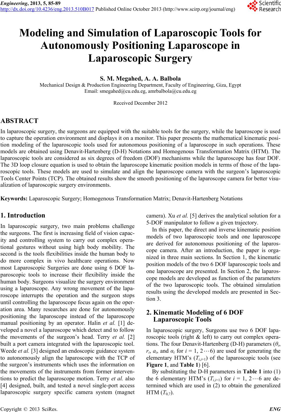
where TBA is the HTM of the right laparoscopic tool, TAB
is the inverse of the HTM of the right laparoscopic tool,
TCD is the HTM of the left laparoscopic tool, TBC is HTM
between the right laparoscopic tool fixed coordinates at
point B and the left laparoscopic tool f ixed coordinates at
C. TAD is the homogenous transformation matrix between
the movable coordinates of the right laparoscopic tool at
point A and the movable coordinates the left laparoscopic
tool at D.
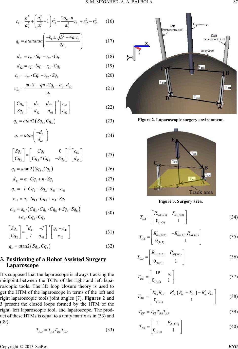
TEF is the HTM of the laparoscope, TEB is the HTM
between the laparoscope fixed coordinates at E and the
right laparoscopic tool fixed coordinates at B. Its as-
sumed that the coordinates in the same direction so the
rotation matrix is unity matrix and there are only transla-
tion in x, y, z directions. TAF is the HTM between the
movable right laparoscopic tool coordinates at A and the
coordinates at the target point (F) but the translation
vector is a ratio (r) of the translation vector of TAD. The
orientation and position (DKPM) of the laparoscope
Camera are calculated directly from TEF. The laparoscope
parameters are determined in terms of those of the lapa-
roscopi c tools [6].
4. Simulation
During surgery operation, the laparoscopic tool is moved
from one point to another on a certain trajectory. Free
and guided trajectories may be selected to avoid ob-
stacles inside the human body. The laparoscopic tools
models are executed using any desired time function for
the path of its TCP to perform a certain task. The ob-
tained mathematical models are simulated to show the
best positioning of the laparoscope in a surgery environ-
ment. The spline trajectory is used to simulate these
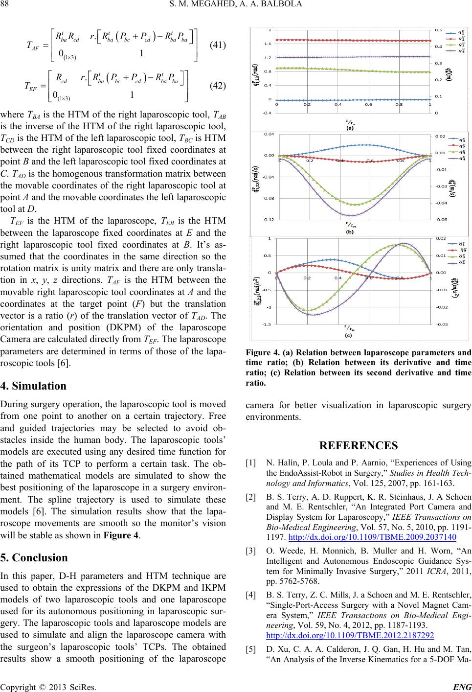
models [6]. The simulation results show that the lapa-
roscope movements are smooth so the monitors vision
will be stable as shown in Figure 4.
5. Conclusion
In this paper, D-H parameters and HTM technique are
used to obtain the expressions of the DKPM and IKPM
models of two laparoscopic tools and one laparoscope
used for its autonomous positioning in laparoscopic sur-
gery. The laparoscopic tools and laparoscope models are
used to simulate and align the laparoscope camera with
the surgeons laparoscopic toolsTCPs. The obtained
results show a smooth positioning of the laparoscope
Figure 4. (a) Relation between laparoscope parameters and
time ratio; (b) Relation between its derivative and time
ratio; (c) Relation between its second derivative and time
ratio.
camera for better visualization in laparoscopic surgery
environments.
REFERENCES
[1] N. Halín, P. Loula and P. Aarnio, “Experiences of Using
the EndoAssi st-Robot in Surgery,” Studies in Health Tech-
nology and Informatics, Vol. 125, 2007, pp. 161-163.
[2] B. S. Terry, A. D. Ruppert, K. R. Steinhaus, J. A Schoen
and M. E. Rentschler, “An Integrated Port Camera and
Display System for Laparoscopy,” IEEE Transactions on
Bio-Medical Engineering, Vol. 57, No. 5, 2010, pp. 1191-
1197. http://dx.doi.org/10.1109/TBME.2009.2037140
[3] O. Weede, H. Monnich, B. Muller and H. Worn, “An
Intelligent and Autonomous Endoscopic Guidance Sys-
tem for Minimally Invasive Surgery,” 2011 ICRA, 2011,
pp. 5762-5768.
[4] B. S. Terry, Z. C. Mills, J. a Schoen and M. E. Rentschler,
“Single-Port-Access Surgery with a Novel Magnet Cam-
era System,” IEEE Transactions on Bio-Medical Engi-
neering, Vol. 59, No. 4, 2012, pp. 1187-1193.
http://dx.doi.org/10.1109/TBME.2012.2187292
[5] D. Xu, C. A. A. Calderon, J. Q. Gan, H. Hu and M. Tan,
“An Analysis of the Inverse Kinematics for a 5-DOF Ma-
S. M. MEGAHED, A. A. BALBOLA
Copyright © 2013 SciRes. ENG
89
nipulator,” International Journal of Automation and
Computing, Vol. 2, 2005, pp. 114-124.
http://dx.doi.org/10.1007/s11633-005-0114-1
[6] S. M. Megahed, Principles of Robot Modelling and Si-
mulation,” John Wiley & Sons Ltd., 1993, pp. 256-261.
[7] A. Balbola, “Modeling and Simulation of Endoscopes for
Autonomously Positioning Videoscope in Laparoscopic
Surgery,” Cairo University, 2013.