 Journal of Biomaterials and Nanobiotechnology, 2013, 4, 374-384 http://dx.doi.org/10.4236/jbnb.2013.44047 Published Online October 2013 (http://www.scirp.org/journal/jbnb) Friction and Wear Behavior of Ti-6Al-7Nb Biomaterial Alloy Mamoun Fellah1*, Omar Assala1, Mohamed Labaïz1, Leila Dekhil2, Alain Iost3 1Surface Engineering and Tribology Team, Laboratory of Metallurgy and Engineering Materials, BADJI Mokhtar-Annaba University, Annaba, Algeria; 2Laboratory of Formability and Metallic Materials, BADJI Mokhtar-Annaba University, Annaba, Algeria; 3La- boratory of Metallurgy, ARTS ET METIERS ParisTech, Lille, France. Email: *mamoun.fellah@yahoo.fr, asslo23@gmail.com, m.labaiz@univ-annaba.org, dekhil23@yahoo.fr, Alain.iost@ensam.eu Received 28 January 2013; revised 1 March 2013; accepted 1 April 2013 Copyright © 2013 Mamoun Fellah et al. This is an open access article distributed under the Creative Commons Attribution License, which permits unrestricted use, distribution, and reproduction in any medium, provided the original work is properly cited. ABSTRACT Titanium has been increasingly applied to biomedical application because of its improved mechanical characteristics, corrosion resistance and biocompatibility. However their application remains limited, due to the low strength and poor wear resistance of unalloyed titanium. The purpose of this study is to evaluate the friction and wear behavior of high-strength titanium alloys: Ti-6Al-7Nb used in femoral stem (total hip prosthesis). The oscillating friction and wear tests have been carried out in ambient air with oscillating tribotester in accord with standards ISO 7148, ASTM G99-95a, ASTM G 133-95 under different conditions of normal applied load (3, 6 and 10 N) and sliding speed (1, 15 and 25 mm·s−1), and as a counter pair we used the ball of 100C 6, 10 mm of diameter. The surface morphology of the titanium alloys has been characterized by SEM, EDAX, micro hardness, roughness analysis measurements. The behav- ior observed for both samples suggests that the wear and friction mechanism during the test is the same for Ti alloys, and to increase resistance to wear and friction of biomedical titanium alloys used in total hip prosthesis (femoral stems) the surface coating and treatment are required. Keywords: Tribological Behavior; Friction and Wear Tests; Biomaterial; Total Hip Prosthesis; Ti-6Al-7Nb 1. Introduction Titanium and its alloys have been used as implant mate- rials due to their very good mechanical and corrosion re- sistance and biocompatibility [1-7]. The most used bio- materials were commercially pure titanium (CP-Ti) which is used in clinics [8,9], although CP-Ti has been pointed out to have disadvantages of low strength, difficulty in polishing, and poor wear resistance [10]. Therefore, Tita- nium is still insufficient for high-stress applications; e.g., long spanned fixed prostheses and the frameworks of removable partial dentures [11,12]. Ti-6Al-4V alloy, originally developed as an aeronau- tical material, has been tested as a replacement for CP-Ti, because of its high mechanical properties with sufficient corrosion resistance [13-17]; however, the cytoxicity of elemental Vanadium is questionable [18-20]. Subse- quently, some researches prove that Vanadium and Alu- minum ions released from this ternary alloy can induce cytotoxic effects or neurological disorders, respectively [21,22]. Also, for long-term, this alloy has transferred in sufficient load to adjacent bones, resulting in bone re- sorption and eventual loosening of the implant [23,24]. Another ternary alloy used as implants was Vanadium free, α + β alloy, especially Ti-6Al-7Nb alloy [25-27] that revealed improved mechanical characteristics, corro- sion resistance and biocompatibility. Developed for or- thopedics application as a wrought material, it has been evaluated as a new alloy for total hip prostheses. Nio- bium exhibits a similar effect to Vanadium in stabilizing β phase in the Ti-Nb binary system, which is necessary for providing the α, β two-phase structure. Therefore, Niobium was used as the ternary element to produce the desirable microstructure in the Ti-6Al-7Nb alloy [28]. As compared with Ti-6Al-4V alloy, in a tensile test, these alloys show slightly lower strength and about 40% higher elongation. In addition, after long term immersion in 1.0% lactic acid, the amount of Titanium ion released from Ti-6Al-7Nb alloy was less than that from Ti-6Al- 4V alloy and comparable to that from titanium [29]. Ti-6Al-7Nb alloy showed castability slightly lower than *Corresponding author. Copyright © 2013 SciRes. JBNB  Friction and Wear Behavior of Ti-6Al-7Nb Biomaterial Alloy 375 that of CP-Ti, but less casting porosity, which is advan- tageous in terms of reliability of castings [29]. Although Ti-6Al-7Nb alloy castings have been inves- tigated for orthopedics application from several aspects such as mechanical properties, corrosion resistance and castability, no studies have reported on friction and wear resistance, which is an important factor for a material for total hip prostheses. In this study, friction and wear characteristics of Ti-6Al-7Nb alloys were evaluated by a ball on disc tribometre in accord with standards ISO 7148, ASTM G99-95a, ASTM G 133-95. 2. Materials and Methods 2.1. Materials The materials used in this study are the Ti-6Al-7Nb as a total hip prosthesis (femoral stem) and Ti-6Al-4V that was cuted from a titanium cylindrical bar correspond to ISO 5832-3 part 3/01-07-199 (was supplied by ENSAM Lille, France). The composition of titanium alloys used in this study is specified in Table 1. It is known that the fixation of the implant is greatly dependent on good me- chanical interlocking between the rough surface of the implant and tissue [30]. So, the surfaces of the alloys were abraded with 600 abrasive papers firstly and pol- ished with colloidal silica, all the samples were cleaned in an ultrasonic bath with acetone, ethanol, and distilled water, respectively, for 10 min and then dried in hot air and saved in the desiccators for use in different charac- terizations. 2.2. Tribological Study Pin on disc, ball on disc and sphere on plan tribological tests (Figures 1 and 2) were carried out using the fol- lowing prosthetic materials: Ti-6Al-4V and Ti-6Al-7Nb alloys, against 100C6 and abrasive paper number 320 (Sic). 2.2.1. Plan Contact The contact pair, which studies the tribological pair, is, in this case, the sample Ti-6Al-7Nb and sandpaper (320 abrasive papers). The parameters taken into account for this test are the applied load and the rotational speed. The test time is kept constant, and the weight loss is the difference in weight of the sample weighed before and after the test with a microelectronic balance whose accu- racy is of the order 10−3 g. The samples were cleaned with acetone before each weight; the surface roughness of the test sample is measured before and after the test. 2.2.2. Friction Behavior In this work, friction and wear tests have been carried out, in ambient air with oscillating tribometer in accord with standards ISO 7148, ASTM G99-95a, ASTM G 133-95 Figure 1. Scheme of the contact geometry (plan contact): 1: speed regulator, 2: support, 3: rotating tray, 4: load applied, 5: sample, 6: retaining frame. Friction pair used: Ti-6Al- 7Nb sliding against number 320 abrasive paper. Sliding dis- tance: 1400 m. Figure 2. (a) Photography and (b) Scheme of the contact geometry (alternative movement) and Tribotester System: 1: table, carry sample on alternative movement (wear track radius = 10 mm), 2: a sensor to measure heat and humidity, 3: ball 100C6 steel, 4: load applied FN, 5: Sample. (Figure 2), under different condition of normal load (3, 6 and 10 N) and sliding speed (1, 15 and 25 mm·s−1), as a counter pair we used the 100C6 ball, 10 mm in diameter as presented in Table 2. 3. Results and Discussion 3.1. Surface and Microstructural Analysis Microstructure 1) An acidic etchant (3 ml HF, 6 ml HNO3 and 100 ml H2O for 10 s to reduce the influence of surface harden- ing. 2) The samples are mechanically polished and chemi- cally etched with a solution of 3 ml HF, 6 ml HNO3 and 100 ml H2O for 10 s to reduce the influence of surface hardening, the microstructure was studied using optical microscopy (Leica DMLM). 3) The microstructure of Titanium alloy was shown in Figure 3 respectively, the photography consisted of glo- Copyright © 2013 SciRes. JBNB  Friction and Wear Behavior of Ti-6Al-7Nb Biomaterial Alloy Copyright © 2013 SciRes. JBNB 376 Table 1. Chemical composition (wt%) of Ti-6Al-7Nb. Element Al Nb V Fe Mo O Si C Ta N Ti % 6.2 7.4 - 0.10 0.005 0.0001 0.0002 0.0015 0.46 - Balance Table 2. Work condition of the alternative movement wear test oscillating tribotester. Friction pairs used 1) Ball 1006C/Ti6Al4V, 2) Ball 1006C/Ti6Al7Nb Sliding speed 1, 15 and 25 mm·s−1 Normal load 3, 6 and 10 N Wear track radius 10 mm 100C6 ball diameter 10 mm Temperature 25˚C Humidity 38% Figure 4. EDAX microanalysis of Ti-6Al-7Nb alloy. The roughness (Figure 8) of the samples in 3D was studied using Surface Data Veeco: Mag 5.0 X, Mode VSI. Roughness Analysis The studied substrates are of biomedical interest. They must therefore meet the standards imposed by the field of biomedicine particularly at the surface of the material deposited on the auricular surfaces of hip prostheses in which Ti-6Al-4V and Ti-6Al-7Nb are the hip implant. The roughness of the samples was obtained (Table 3 and Figures 8(a)-(c)), meets the standards of biomedicine, namely, roughness for metal parts as specified in ISO 7206-2:1996 [32]. The roughness values samples were 5.03 and 0.01 µm for Ti-6Al-7Nb before and after polishing respectively and 0.06 µm for Ti-6Al-4V after polishing. Figure 3. Optical micrographs showing the microstructure of Ti-6Al-7Nb alloy etched with a solution of 3 ml HF, 6 ml HNO3 and 100 ml H2O for 10 s the figure consisted of glo- bular and acicular α grains (white grains) within a matrix containing equiaxial grains β (dark grains). bular and acicular α grains (white grains) within a matrix containing equiaxial grains β (dark grains). The acicular shape of the α phase is present in the Figure 3 in an ar- rangement known as basket-weave which characterizes the Widmanstätten structure. 3.2. Tribological Study 4) The chemical composition presented in Table 1 was acquired using spectrometer (Spectrolab) and energy- dispersive spectroscopy (EDS, PHILIPS XL 30 ESEM- FEG, and EDX IMIX-PTS. 3.2.1. Plan Contact The weight loss (Figure 9) of titanium samples, tested at 3.5 N loads, is approximately proportional to the number of revolutions. Nevertheless, the wear was systematically greater to Ti-6Al-7Nb as expected. The behavior ob- served for both samples suggests that the wear mecha- nism during the test is the same (abrasive wear). In the case of Ti-6Al-4V samples, its weight loss was ~85% of the one observed for the Ti-6Al-7Nb samples. According to the Archard’s law, the volumetric loss of the material is inversely proportional to the hardness value of the material [33]. This implies that the higher the hardness of the material, the smaller is the volume loss. The present alloys exhibit significant difference in hardness values, so that the experimental sliding wear data correlate well 5) The titanium samples were examined using energy dispersive X-Ray (EDX) analysis. The spectra for the overall analysis are shown in Figures 4 and 5. The EDX spectrum shows different peaks that correspond to the different elements contained in the substrate. In the case of Ti-6Al-7Nb, the Ti peak is more pronounced than that of aluminum (Al), Niobium (Nb), iron (Fe), Molybde- num (Mo) and tantalum (Ta) are also present. The che- mical compositions of the studied samples were in com- pliance with that of a Ti-6Al-7 Nb. The instrumented microharndnesse (Figures 6 and 7), was studied using ZWICK 2.5.  Friction and Wear Behavior of Ti-6Al-7Nb Biomaterial Alloy 377 Figure 5. XRD patterns of Ti-6Al-7Nb alloy. Figure 6. Example of micro-hardness P-h curve [31]. with Archard’s law. 3.2.2. Friction Coefficient It is instead to know the wear and friction coefficient of ball 100C6 steel (Figure 10), before studying the coeffi- cient of friction of samples. The evolution curves of friction coefficient of Ti6A7Nb versus sliding distance (number of cycles) Table 4 and Figures 11-18 are almost the same form wholes in terms of load and speed. The analysis of these curves to dis- tinguish several periods, or successive regimes of friction and wear: 1) The first period, during which the friction coeffi- cient increases rapidly, an accommodation, is the surface of the first body the most ductile [34], in this case the steel. The relief is so attenuated; the roughness of the surface of the steel is reduced by plastic deformation 2) The second period is characterized by a slight de- crease in the friction coefficient. Probably, the third body on the track generated by frictional wear of the steel plays a role comparable to that of a solid lubricant. 3) The third period is defined by a significant increase in the friction coefficient. The third body is fragmented 010 20 30 0 10 20 30 40 50 Force standar d e n N Empreinte (a) 010 20 30 0 10 20 30 40 50 Force standard en N Empreinte (b) Figure 7. P–h curves during micro hardness experiments with loading speed (0.2 mm·min−1), under a maximum load (50 N) of: (a) Ti-6Al-4V; (b) Ti-6Al-7Nb. and oxidizes very probably plays a role abrasive, then the virtual stabilization of the friction coefficient. 4) The fourth and final period is near stabilization of the friction coefficient. The friction test results of Ti-6Al-7Nb and Ti-6Al-4V, are illustrated in Table 4 and Figures 11-18 respectively. Copyright © 2013 SciRes. JBNB  Friction and Wear Behavior of Ti-6Al-7Nb Biomaterial Alloy 378 Figure 8. The optical 3D photo of Ti alloys, (a) Ti-6Al-7Nb before polishing as received as femoral stem; (b) Ti-6Al- 7Nb after polishing; (c) Ti-6Al-4V after polishing. Table 3. Surfaces statistics of Ti alloys as received (stem femoral) and after polishing. Ti-6Al-7N as received Ti-6Al-7Nb after preparation Ti-6Al-4V after preparation Ra (µm) 5.03 0.01 0.06 Rq (µm) 7.42 0.02 0.08 Rz (µm) 45.20 0.57 1.0.5 Rt (µm) 40.43 0.54 1.19 Figure 9. Wear diagrams (weight loss (g·cm−3)) of Ti-6Al- 7Nb, Ti-6Al-4V and ceramic sliding against (abrasive paper number 320). Figure 10. Wear marks of 100C6 steel ball under the fol- lowing conditions: time = 1 h, FN = 10 N, sliding speed 8 mm/s with a same oscillating tribotester [31]. It is seen from Figure 11 that, the friction coefficient showed a lower value (approx. 0.248) up to 20 cycles and then it increased to the average 0.4 value between 40 and 1000 distance (cycles). The reason might be due to an oxide layer formed on Ti-6Al-7Nb and, therefore, the coefficient of friction showed the lower value until 20 m. However, that oxide layer was torn and then 1006C ball was completely touched on the substrate and, therefore, the friction coefficient was obtained at a higher value (0.538). In Figure 12, it is seen that the friction coeffi- cient curves of Ti-6Al-7Nb, are the same form for all test conditions sliding speed and normal load applied, the average friction coefficient was obtained as 0.54 at sliding speed 25 mm·s−1 under 10 N, It is also obvious in Figure 12, that the coefficient of friction displayed a lower value of 0.129 up to 20 cycle at sliding speed 1 mm·s−1, under 3 N of normal load and then it sharply. Increased to the average value of 0.518 (Table 4) for the same conditions 1 mm·s−1. 1) Influence of the Load Applied to the Friction Coefficient The influence of normal load applied on the evolution of friction coefficient of Ti-6Al-7Nb and Ti-6Al-4V under different condition of loads (3, 6 and 10 N) at slid- ing speeds (1, 15 and 25 mm·s−1), was represented in Table 5 and Figures 13-15. It is seen in the Figure 13, that the mean coefficient of friction at 1 mm·s−1 it Copyright © 2013 SciRes. JBNB  Friction and Wear Behavior of Ti-6Al-7Nb Biomaterial Alloy Copyright © 2013 SciRes. JBNB 379 Table 4. Values of friction coefficient of Ti-6Al-7Nb versus sliding distance (1, 15 and 25 mm·s−1) under different loads 3, 6 and 10 N. Speed 1 mm·s−1 15 mm·s−1 25 mm·s−1 FN (N) Star COF Min COF Max COF Mean COF PH Ca (Mpa) Star COF Min COF Max COF Mean COF PH Ca (Mpa) Star COF Min COf Max COF Mean COF PHCa (Mpa) 3 N 0.129 0.068 0.589 0.339 524 0.2480.2480.5380.4 531 0.3490.349 0.49 0.419 532 6 N 0.325 0.197 0.546 0.36 660 0.4050.3390.5080.413 670 0.3330.333 0.482 0.418 670 10 N 0.251 0.213 0.518 0.357 783 0.3970.3250.48 0.398 795 0.3670.344 0.54 0.407 795 PH Ca: Hertz pressure (calculated) (Mpa); Star COF: the start value of coefficient of friction; Min COF: the minimum value of coefficient of friction; Mean COF: the mean value of coefficient of friction; Max COF: the maximum value of coefficient of friction; FN (N): a normal load applied (N). Figure 13. Friction coefficient vs sliding distance for Ti al- loys and ceramic under different conditions of load 3, 6 and 10 N at 1 mm·s−1 sliding speed. Figure 11. Friction coefficient vs. sliding distance for Ti- 6Al-7Nb under 3 N applied load at 15 mm·s−1 sliding speed. Figure 14. Friction coefficient vs sliding distance for Ti al- loys and ceramic under different conditions of load 3, 6 and 10 N at 15 mm·s−1 sliding speed. Figure 12. Friction coefficient vs. sliding distance for Ti- 6Al-7Nb under different conditions of load 3, 6 and 10 N at tows sliding speed 15 and 25 mm·s−1. reaches the mean value of 0.339, 0.36 and 0.357 of Ti-6Al-7Nb under normal load 3, 6 and 10 N respec- tively, also it seen in the some Figure 13, that the Ti- 6Al-4V almost has the same mean value of friction co- efficient of Ti-6Al-7Nb. The Figures 14 and 15 are presented the evolution of friction coefficient of Ti-6Al-7Nb and Ti-6Al-4V vs. sliding distance under different conditions of load 3, 6 and 10 N at sliding speeds 1 and 25 mm·s−1 respectively, it seen that the samples almost has the same mean value of friction coefficient that’s increased to the average values of (0.37 to 0.5). Figure 15. Friction coefficient vs sliding distance for Ti al- loys and ceramic under different conditions of load 3, 6 and 10 N at 25 mm·s−1 sliding speed. 2) Influence of Speed  Friction and Wear Behavior of Ti-6Al-7Nb Biomaterial Alloy 380 Figure 16. friction coefficient vs sliding distance for Ti al- loys and ceramic under different conditions of sliding speed 1, 15 and 25 mm·s−1 at normal load 3 N. Figure 17. Friction coefficient vs sliding distance for Ti al- loys and ceramic under different conditions of sliding speed 1, 15 and 25 mm·s−1 at normal load 6 N. Figure 18. Friction coefficient vs sliding distance for Ti al- loys and ceramic under different conditions of sliding speed 1, 15 and 25 mm·s−1 at normal load 10 N. Figures 16-18, represented the influence of loads applied to the evolution of friction coefficient of Ti-6Al- 7Nb, and Ti-6Al-4V under different condition sliding speeds (1, 15 and 25 mm·s−1), at 3, 6 and 10 N load applied respectively. It is seen that the mean coefficient of friction of the samples displayed a lower value at 1 mm·s−1 sliding speed, and then it sharply increased to the average value with increasing of sliding speed as show- ing in the Table 5 and Figure 19. 3.2.3. Wear In the wear test, the volumetric wear rate was calculated by the help of mechanical profilometer as 57.62 × 10⁻³ mm3·N·mm−1 for the Ti-6Al-Nb. A 100C6 ball did the grinding from the sample surface, that is, abrasive wear occurred on the surface and this is illustrated in Figures 20 and 21. Volumetric wear was determined as 5.48 × 10⁻³, 9.64 × 10⁻³ and 13.12 × 10⁻³ mm3·N·mm−1 at 1 mm·s−1 sliding speed under loads 3, 6 and 10 respectively. Finally, the volumetric wear was a same for a both slid- ing speed 15 and 25 between 20.67 × 10⁻³ mm3·N·mm−1 and 57.62 × 10⁻³ mm3·N·mm−1. Table 6 and Figure 19, provides the wear volume of the investigated alloys as a function of the sliding speed. The volumetric wear data reveal that the volume loss, irrespective of alloy com- position and microstructure, increases as the sliding speed increases. Friction versus wear: The strength of materials de- pends on three groups of factors in friction conditions [35]. Those factors are shown as follows: 1) Internal reasons determined material property; 2) Friction type (slipping, rolling) and working con- ditions (relative movement speed, load, application type, temperature); and 3) Working environment and lubricants. 4. Conclusions Wear characteristics of high-strength titanium alloys Ti-6Al-7Nb were evaluated in a wear test simulating the friction for Total hip prosthesis application. The oscillat- ing friction and wear resistance have been carried out in ambient air with oscillating tribotester in accord with standards ISO 7148, ASTM G99-95a and ASTM G133- 95. On the one hand, the friction and wear tests were carried out to see the type of wear and to quantify the weight loss; on the other hand, to see the variation in the friction coefficient of the studied couples under different conditions of load (3, 6 and 10 N) and sliding speed (1, 15 and 25 mm·s−1) as counter pairs, we used the ball of 100C6 steel, 10 mm in diameter. The following observa- tions and conclusions were obtained: 1) The wear resistance of Ti-6Al-7NB alloy is sub- stantially lower than that of the Ti-6Al-4V tested under deferent conditions of load and sliding speed. The extent of wear is smallest for Ti-6Al-4V with highest hardness. 2) The coefficient friction as shown in Figure 19, of both alloys increases with increasing sliding speed. How- ever, Ti-6Al-7Nb alloy shows no significant variation of coefficient of friction with (15 and 25 mm·s−1) sliding speeds, while the coefficient of Ti-6Al-4V increases linearly with increasing sliding speed. This behavior is attributed to the predominant wear mechanism. 3) The two Ti alloys had similar friction and wear per- formance, although their grain structures and composi- Copyright © 2013 SciRes. JBNB  Friction and Wear Behavior of Ti-6Al-7Nb Biomaterial Alloy Copyright © 2013 SciRes. JBNB 381 Table 5. Mean value of coefficient of friction of Ti alloys and ceramic under different conditions of sliding speeds (1, 15 and 25 mm·s−1) and normal loads (3, 6 and 10 N). Speed 1 mm·s−1 15 mm·s−1 25 mm·s−1 Fn (N) Ti-6Al-7Nb Ti-6Al-4V Ti-6Al-7Nb Ti-6Al-4V Ti-6Al-7Nb Ti-6Al-4V 3 (N) 0.339 0.356 0.4 0.497 0.419 0.489 6 (N) 0.36 0.297 0.413 0.473 0.418 0.565 10 (N) 0.357 0.374 0.398 0.452 0.407 0.476 Table 6. Volumetric wear rate of Ti-6Al-7Nb and Ti-6Al-4V under different conditions of sliding speeds (1, 15 and 25 mm·s−1) and normal loads (3, 6 and10 N). Volumetric wear mm3·N·mm−1 Sliding speed mm/s Load (N) Ti-6Al-4V Ti-6Al-7Nb 3 4.45 × 10⁻³ 5.48 × 10⁻³ 6 8.24 × 10⁻³ 9.64 × 10⁻³ 1 mm·s−1 10 11.08 × 10⁻³ 13.12 × 10⁻³ 3 20.35 × 10⁻³ 22.06 × 10⁻³ 6 37.98 × 10⁻³ 38.1 × 10⁻³ 15 mm·s−1 10 51.55 × 10⁻³ 57.35 × 10⁻³ 3 27.32 × 10⁻³ 31.38 × 10⁻³ 6 42.15 × 10⁻³ 45.28 × 10⁻³ 25 mm·s−1 10 54.21 × 10⁻³ 57.62 × 10⁻³ Figure 19. Mean coefficient of friction of Ti alloys and cera- mic under different conditions of sliding speeds (1, 15 and 25 mm·s−1) and applied loads (3, 6 and 10 N). Figure 20. The worn surfaces, severe deformation and plas- tic flow of Ti-6Al-4V, sliding against ball 100C6 steel (r = 10 mm): (a) Wear marks under normal load 3, 6 and 10 N at sliding speed 15 mm·s−1; (b) and (c) At normal load 6 N and sliding speed 15 mm·s−1; (d) and (e) At normal load 10 N and sliding speed 15 mm·s−1; (f) At normal load 10 N and slid- ing speed 25 mm·s−1. Arrows indicate the sliding direction. tions are different. 4) Large frictional fluctuations occurred, probably caused by formation and periodic, localized fracture of a transfer layer. 5) Higher friction coefficient with larger fluctuation and higher wear rate were observed at the higher siding speed. plastic deformation and adhesive wear at elevated speed. 6) In all curves under deferent conditions, the friction coefficient firstly decreases and then increases as a func- tion of the sliding distance. The evolution of the friction coefficient is related to composition of the worn surfaces. 8) The weight loss quantifying the wear of a soft body slipping on a hard surface is proportional not only to the distance from the slip but also with the normal load applied. 7) The wear mechanism of Ti-6Al-4V transforms from ploughing and peeling off wear at low sliding speed to 9) The sliding speed has a principal effect to act on the temperature of the contact zone. Going beyond a critical 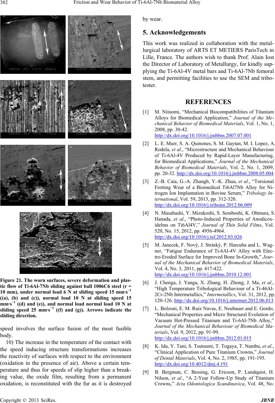 Friction and Wear Behavior of Ti-6Al-7Nb Biomaterial Alloy 382 Figure 21. The worn surfaces, severe deformation and plas- tic flow of Ti-6Al-7Nb sliding against ball 1006C6 steel (r = 10 mm), under normal load 6 N at sliding speed 15 mm·s−1 ((a), (b) and (c)), normal load 10 N at sliding speed 15 mm·s−1 ((d) and (e)), and normal load normal load 10 N at sliding speed 25 mm·s−1 ((f) and (g)). Arrows indicate the sliding direction. speed involves the surface fusion of the most fusible body. 10) The increase in the temperature of the contact with the speed inducing structure transformations increases the reactivity of surfaces with respect to the environment (oxidation in the presence of air). Above a certain tem- perature and thus for speeds of slip higher than a break- ing value, the oxide film, resulting from a permanent oxidation, is reconstituted with the fur as it is destroyed by wear. 5. Acknowledgements This work was realized in collaboration with the metal- lurgical laboratory of ARTS ET METIERS ParisTech in Lille, France. The authors wish to thank Prof. Alain Iost the Director of Laboratory of Metallurgy, for kindly sup- plying the Ti-6Al-4V metal bars and Ti-6Al-7Nb femoral stem, and permitting facilities to use the SEM and tribo- tester. REFERENCES [1] M. Niinomi, “Mechanical Biocompatibilities of Titanium Alloys for Biomedical Application,” Journal of the Me- chanical Behavior of Biomedical Materials, Vol. 1, No. 1, 2008, pp. 30-42. http://dx.doi.org/10.1016/j.jmbbm.2007.07.001 [2] L. E. Murr, S. A. Quinones, S. M. Gaytan, M. I. Lopez, A. Rodela, et al., “Microstructure and Mechanical Behaviour of Ti-6Al-4V Produced by Rapid-Layer Manufacturing, for Biomedical Applications,” Journal of the Mechanical Behavior of Biomedical Materials, Vol. 2, No. 1, 2009, pp. 20-32. http://dx.doi.org/10.1016/j.jmbbm.2008.05.004 [3] Z.-B. Caia, G.-A. Zhangb, Y.-K. Zhua, et al., “Torsional Fretting Wear of a Biomedical Ti6Al7Nb Alloy for Ni- trogen Ion Implantation in Bovine Serum,” Tribology In- ternational, Vol. 59, 2013, pp. 312-320. http://dx.doi.org/10.1016/j.triboint.2012.06.009 [4] N. Masahashi, Y. Mizukoshi, S. Semboshi, K. Ohmura, S. Hanada, et al., “Photo-Induced Properties of Anodicox- idelms on Ti6Al4V,” Journal of Thin Solid Films, Vol. 520, No. 15, 2012, pp. 4956-4964. http://dx.doi.org/10.1016/j.tsf.2012.03.026 [5] M. Janecek, F. Nový, J. Stráský, P. Harcuba and L. Wag- ner, “Fatigue Endurance of Ti-6Al-4V Alloy with Elec- tro-Eroded Surface for Improved Bone In-Growth,” Jour- nal of the Mechanical Behavior of Biomedical Materials, Vol. 4, No. 3, 2011, pp. 417-422. http://dx.doi.org/10.1016/j.jmbbm.2010.12.001 [6] J. Chenga, J. Yanga, X. Zhang, H. Zhong, J. Ma, et al., “High Temperature Tribological Behaviour of a Ti-46Al- 2Cr-2Nb Intermetallics,” Intermetallics, Vol. 31, 2012, pp. 120-126. http://dx.doi.org/10.1016/j.intermet.2012.06.013 [7] L. Bolzoni, E. M. Ruiz Navas, E. Neubauer and E. Gordo, “Mechanical Properties and Micro Structural Evolution of Vacuum Hot-Pressed Titanium and Ti-6Al-7Nb Alloy,” Journal of the Mechanical Behaviour of Biomedical Ma- terials, Vol. 9, 2012, pp. 91-99. http://dx.doi.org/10.1016/j.jmbbm.2012.01.015 [8] K. Ida, Y. Tani, S. Tsutsumi, T. Togaya, T. Nambu, et al., “Clinical Application of Pure Titanium Crowns,” Journal of Dental Materials, Vol. 4, No. 2, 1985, pp. 191-195. http://dx.doi.org/10.4012/dmj.4.191 [9] B. Bergman, C. Bessing, G. Ericson, P. Lundquist, H. Nilson, et al., “A 2-Year Follow-Up Study of Titanium Crowns,” Acta Odontologica Scandinavica, Vol. 48, No. Copyright © 2013 SciRes. JBNB  Friction and Wear Behavior of Ti-6Al-7Nb Biomaterial Alloy 383 2, 2011, pp. 113-117. [10] T. Hirata, T. Nakamura, F. Takashima, T. Maruyama, M. Taira, et al., “Studies on Polishing of Ag-Pd-Cu-Au Alloy with Five Dental Abrasives,” Journal of Oral Rehabilita- tion, Vol. 28, No. 8, 2011, pp. 773-777. http://dx.doi.org/10.1046/j.1365-2842.2001.00737.x [11] T. Kawazoe and K. Suese, “Clinical Application of Tita- nium Crowns,” Dental Materials Journal, Vol. 30, No. 3, 1989, pp. 317-328. [12] A. Kuroiwa and Y. Igarashi, “Application of Pure Tita- nium to Metal Framework,” Nihon Hotetsu Shika Gakkai Zasshi, Vol. 42, No. 4, 1998, pp. 547-558. http://dx.doi.org/10.2186/jjps.42.547 [13] M. A. Khan, R. L. Williams and D. F. Williams, “In-Vitro Corrosion and Wear of Titanium Alloys in the Biological Environment,” Biomaterials, Vol. 17, No. 22, 1996, pp. 2117-2126. http://dx.doi.org/10.1016/0142-9612(96)00029-4 [14] S. Tamilselvi, R. Murugaraj and N. Rajendran, “Electro- chemical Impedance Spectroscopic Studies of Titanium and Its Alloys in Saline Medium,” Material and Corro- sion, Vol. 58, No. 2, 2007, pp. 113-119. http://dx.doi.org/10.1002/maco.200603979 [15] S. Tamilselvi and N. Rajendran, “In Vitro Corrosion Be- havior of Ti-5Al-2Nb-1Ta Alloy in Hanks Solution,” Materials and Corrosion, Vol. 58, No. 4, 2007, pp. 285- 289. http://dx.doi.org/10.1002/maco.200604001 [16] A. Guitar, G. Vigna and M. I. Luppo, “Microstructure and Tensile Properties after Thermo Hydrogen Processing of Ti-6Al-4V,” Journal of Mechanical Behavior of Bio- medical Materials, Vol. 2, No. 2, 2009, pp. 156-163. http://dx.doi.org/10.1016/j.jmbbm.2008.06.002 [17] C. R. Ramos-Saenz, F. A. Sundaram and N. Diffoot- Carlo, “Tribological Properties of Ti-Based Alloys in Si- mulated Bone Implant Interface with Ringer’s Solution at Fretting Contacts,” Journal of Mechanical Behavior of Biomedical Materials, Vol. 3, No. 8, 2010, pp. 549-558. http://dx.doi.org/10.1016/j.jmbbm.2010.06.006 [18] R. C. Browne, “Vanadium Poisoning from Gas Tur- bines,” British Journal of Industrial Medicine, Vol. 2, No. 12, 1955, pp. 57-59. [19] S.-G. Sjöberg, “Vanadium Dust, Chronic Bronchitis and Possible Risk of Emphysema: A Follow-Up Investigation of Workers at a Vanadium Factory,” Journal of Internal Medicine, Vol. 154, No. 5, 1956, pp. 381-386. [20] P. G. Laing, “Clinical Experience with Prosthetic Materi- als: Historical Perspectives, Current Problems and Future Directions. Corrosion and Degradation of Implant Mate- rials,” ASTM-STP 684, B. C. Syrett and A. Acharya, Eds., American Society for Testing and Materials, 1979, pp. 199-211. [21] M. Geetha, A. K. Singh, R. Asokamini and A. K. Gogia, “Ti Based Biomaterials, the Ultimate Choice for Ortho- paedic Implants—A Review,” Progress in Materials Sci- ence, Vol. 54, No. 3, 2009, pp. 397-425. http://dx.doi.org/10.1016/j.pmatsci.2008.06.004 [22] G. B. Van der Volt, E. Marani, S. Tio and F. A. De Wolff, “Aluminum Neurotoxicity,” In: W. Graumann and J. Drukker, Eds., “Histo- and Cyto-Chemistry as a Tool in Environmental,” Toxicology, Fisher, Stuttgart, Germany, 1991, pp. 235-242. [23] D. R. C. McLachlan, G. Farnees and I. T. Galin, “Bio- logical Aspects of Metals and Metal Related Diseases,” Ravan Press, New York, 1983. [24] D. Scharnweber, “Degradation (in Vitro-in Vivo Corro- sion),” In: J. A. Helsen and H. Jürgen Breme, Eds., Met- als as Biomaterials, John Willey & Sons, London, 1998, pp. 101-151. [25] M. F. Lopez, L. Soriano, F. J. Palomares, M. Sanchez- Agudo, G. G. Fuentes, et al., “Soft X-Ray Absorption Spectroscopy Study of Passive and Oxide Layers of Tita- nium Alloys,” Surface and Interface Analysis, Vol. 33, No. 7, 2002, pp. 570-579. http://dx.doi.org/10.1002/sia.1422 [26] C. Morand, M. F. Lopez, A. Gutierrez and J. A. Jimenez, “AFM and SEM Characterization of Non-Toxic Vana- dium-Free Ti Alloys Used as Biomaterials,” Applied Sur- face Science, Vol. 220, No. 1-4, 2003, pp. 79-87. http://dx.doi.org/10.1016/S0169-4332(03)00746-3 [27] M. F. Lopez, J. A. Jimenez and A. Gutierrez, “Corrosion Study of Surface-Modified Vanadium-Free Titanium Al- loys,” Electrochimica Acta, Vol. 48, No. 10, 2003, pp. 1395-1401. http://dx.doi.org/10.1016/S0013-4686(03)00006-9 [28] M. F. Semlitsch, H. Weber and R. M. Streicher, “Joint Replacement Components Made of Hot-Forged and Sur- face-Treated Ti-6Al-7Nb Alloy,” Biomaterials, Vol. 13, No. 11, 1992, pp. 781-888. http://dx.doi.org/10.1016/0142-9612(92)90018-J [29] E. Kobayashi, T. J. Wang, H. Doi, T. Yoneyama and H. Hamanaka, “Mechanical Properties and Corrosion Resis- tance of Ti-6Al-7Nb Alloy Dental Castings,” Journal of Materials Science: Materials in Medicine, Vol. 9, No. 10, 1998, pp. 567-574. http://dx.doi.org/10.1023/A:1008909408948 [30] E. Confortoa, B.-O. Aronssonb, A. Salitoc, C. Crestoud and D. Caillard, “Rough Surfaces of Titanium and Tita- nium Alloys for Implants and Prostheses,” Materials Science and Engineering C: Biomimetic and Supramole- cular systems, Vol. 24, No. 5, 2004, pp. 611-618. [31] Brahim TLILI, “Caractérisation de Films durs Multicou- ches Elaborés par Pulvérisation Magnétron. Influence des Conditions d’Élaboration sur Leurs Propriété,” Le 9 Dé- cembre 2010 École Doctorale No. 432: Sciences des Mé- tiers de l’Ingénieur Doctorat ParisTech Pastel-00573968, Version 1-6, 2011. [32] Norme Internationale (F) Implants Chirurgicaux—Pro- thèses Partielles et Totales de l’Articulation de la Han- che—Partie 2, ISO 7206-2, Surfaces Articulaires Con- stituées de Matériaux Métalliques, Céramiques et Plasti- ques, 1996. [33] J. F. Archard, “Contact and Rubbing of Flat Surfaces,” Journal of Applied Physics, Vol. 24, No. 8, 1953, pp. 981-988. http://dx.doi.org/10.1063/1.1721448 [34] L. Avril, “Elaboration de Revêtements sur Acier Inoxy- dable Simulation de la Fusion par Irradiation Laser Carac- Copyright © 2013 SciRes. JBNB  Friction and Wear Behavior of Ti-6Al-7Nb Biomaterial Alloy Copyright © 2013 SciRes. JBNB 384 térisation Structurale, Mécanique et Tribologique,” Thèse, Ecole Nationale Superieure (432), n° d’ordre 2003-16. [35] H. Paetzold and E. Ilinich, “Determination of the Dy- namic Friction Coefficient of Cartilage with Different Biomaterials,” Journal of Biomechanics, Vol. 41, No. S1, 2008.
|