Energy and Power Engineering, 2013, 5, 479-482
doi:10.4236/epe.2013.54B092 Published Online July 2013 (http://www.scirp.org/journal/epe)
Protection Schemes for Uniline Zone in Bilateral AT
Traction Power Supply System
Zhengqing Han, Zeyuan Yan, Yujie Xia, Bo Li
School of Electrical Engineering, Southwest Jiaotong University, Chengdu, Sichuan, China
Received March, 2013
ABSTRACT
With the rapid development of the construction of high-speed railway in china, higher levels of power quality and
reliability of traction power supply systems are required. The combination of bilateral power supply technology with
AT traction power supply technology can better meet the needs of develo pment of high-speed railways, which will re-
quire new protection approaches to be proposed. Thus, corresponding protection schemes will be of great significance
for the application and pro motion of bilateral power supply technology.
Keywords: High-speed Railway; Bilateral Power Supply; AT Power Supply; Protection Schemes
1. Introduction
In the past, due to the restrictions of management modes
of power grid and limitations of protection schemes, uni-
lateral power supply systems have been used while bilat-
eral power supply technology has not been used in prac-
tical railway projects [1]. Thus, researches on protection
schemes of bilateral power supply system have de-
creased.
With the improvement of power systems, the voltage
class of major network has been generally increased to
220 kV or above 220 kV level, thus, the load capability
of local power systems is enhanced, and the safety and
stability of electric networks are increasingly improved,
which makes the application of bilateral power supply
systems possible. Current calculations, protection schemes
and the advantages of bilateral power supply are con-
cluded briefly in reference [2], meanwhile, trial run is
conducted, which demonstrates the feasibility and tech-
nical advantages of a bilateral power supply system.
Protection schemes of bilateral power supply systems
under direct power supply mode are analyzed in refer-
ence [3]. Electrical characteristics of the bilateral power
supply system and T-R short-circuit current and imped-
ance parameters of traction electric network are analyzed
in this article, through which protection schemes of bi-
lateral power supply systems in uniline zone are put for-
ward.
2. Introduction of Bilateral Power Supply
System
The contact line system is separate at substations and
section posts, and thus, the contact line between two sub-
stations is divided into two independent power supply
sections, called as feeding sections[4]. Each feeding sec-
tion respectively gains power from one substation, which
is defined as a unilateral power supply. If power is
gained from both sub stations at the same time, it is called
a bi- lateral power supply mode. Under bilateral power
supply mode, section posts are set up between two sub-
stations, those two feeding sections are connected by a
circuit breaker, and electric locomotives and motor train
units can gain power from the two substations at the
same time.
Unlined zone in bilateral AT traction power supply
system is shown in Figure 1.
3. Short Circuit Characteristics of Bi l a t e r al
Power Supply System
Equivalent circuit of unlined zone in bilateral power sup-
ply system is shown in Figure 2.
The equivalent circuit can be further simplified into
Figure 3.
In Figure 3,23
23
Azz
zz
z
, 1
, 2
and 3
I
I
I
are
equivalent currents respectively, .
27.5
SSA SSBkUU V
Figure 1. Unlined zone in bilateral AT power supply system.
Copyright © 2013 SciRes. EPE
Z. Q. HAN ET AL.
480
T
R
F
SSA
U
A
l
x
SSB
U
A
L
2
z
1
z
3
z
SP
B
L
B
l
3
I
1
I
2
I
1R
I
2R
I
SP
U
Figure 2. Equivalent circuit of unlined zone in bilateral
traction power supply system.
SSA
U
A
lz
1
SSB
U

xlz
AA
xz
A

xDz
A
D
x
xz
B
1


xDLlz
BBA


BB
Llz
1
1
I
3
I
2
I
BA
Lz
B
z
1
SP
U
Figure 3. Simplified equivalent circuit.
According to Figure 3, using voltage equation, the
short circuit impedance and current of the two substa-
tion A and B are:
1
2
13
23
1
1
SSA
B
A
SSAA ABB
SSB
B
A
SSBA BBA
B
AB
A
AB
Ull
x
Zzlzx
I
Dl
Ull
x
Zzlzx
I
Dl
l
II
ll
l
II
ll

 








(1)
In equation (1), A
l and
B
l
L
are distance from sub-
station A and B to fault poin t. Measuring the shor t circuit
impedance of feeding section at section post feeder:
A

2
1
SP
B
A
SPA BBBA
Ull
x
ZzlLzx
I
Dl

  

 (2)
when T-R short circuit takes place in feeding section
B
L,
the measured value of impedance at section post feeder:

1
1
SP
B
A
SPA AABB
Ull
x
ZzlLzx
I
Dl

  

 (3)
4. Simulation of Short Circuit
Characteristics
The simplified circuit is illustrated above by ignoring the
self-impedance of auto-transformer and the rail-earth
leakage reactance. The equations of short circuit imped-
ance are concluded. Characteristic curves of short circuit
impedance are gained by simulating with MATLAB /
SIMULINK models.
4.1. Simulation of Short-circuit Fault Current
When T-R fault occurs in unlined zones, the measured
currents of two substation and relationship between cur-
rents of fault points and distance are sh own as follows:
From Figure 4, the ratio of su bstation (A and B) feed-
er fault current to fault poin t current is gained and shown
in Figure 5. 1
I
(2
I
) is the value of fault current of sub-
station A (B) multiplies 0.5, and 3
I
is the value of fault
point current multiplies 0.5. A(l
B
l) is the distance from
substation A (B) to the fault point and the distance be-
tween substation A and B is L.
4.2. Simulation of Short-circuit Impedance
When the T-R short circuit fault takes place in unlined
zone in the system, based on equation (1), using MAT-
LAB, the curve of short-circuit impedance (
Z
) of sub-
station A can be drawn and illustrated in Figure 6.
It can be seen from Figure 6 that the simulation results
are quite close to calculated values, which demonstrates
that it is feasible to ignore the self-impedance of auto-
transformers and leakage reactance of rails to earth.
Figure 4. Relationship between T-R fault current of substa-
tion A (B) and distance.
Figure 5. Ratio of feeder fault current to fault point current.
Copyright © 2013 SciRes. EPE
Z. Q. HAN ET AL. 481
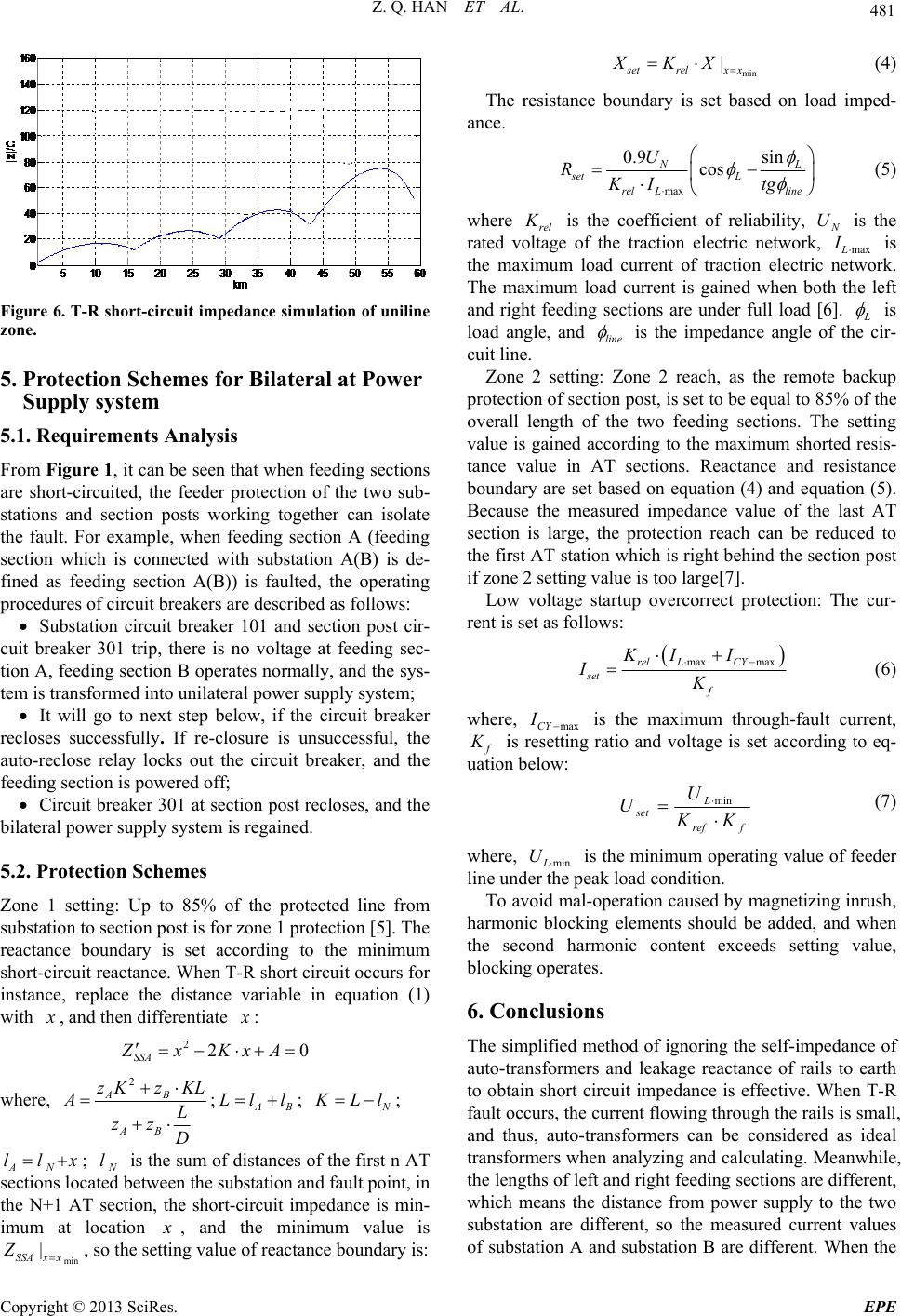
Figure 6. T-R short-circuit impedance simulation of uniline
zone.
5. Protection Schemes for Bilateral at Power
Supply system
5.1. Requirements Analysis
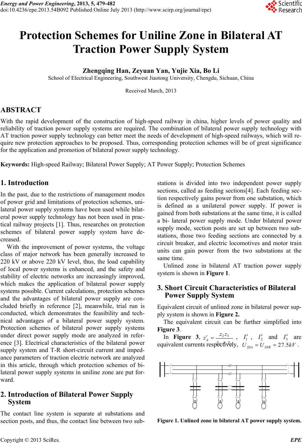
From Figure 1, it can be seen that when feeding sections
are short-circuited, the feeder protection of the two sub-
stations and section posts working together can isolate
the fault. For example, when feeding section A (feeding
section which is connected with substation A(B) is de-
fined as feeding section A(B)) is faulted, the operating
procedures of circuit breakers are described as follows:
Substation circuit breaker 101 and section post cir-
cuit breaker 301 trip, there is no voltage at feeding sec-
tion A, feeding section B operates normally, and the sys-
tem is transformed into unilateral power supply syste m;
It will go to next step below, if the circuit breaker
recloses successfully. If re-closure is unsuccessful, the
auto-reclose relay locks out the circuit breaker, and the
feeding section is powered off;
Circuit breaker 301 at section po st recloses, and the
bilateral power supply system is rega ined.
5.2. Protection Schemes
Zone 1 setting: Up to 85% of the protected line from
substation to section post is for zone 1 protection [5]. The
reactance boundary is set according to the minimum
short-circuit reactance. When T-R short circuit occurs for
instance, replace the distance variable in equation (1)
with
x
, and then differentiate
x
:
220
SSA
ZxKxA
 
where, 2
AB
AB
zKzKL
AL
zz
D


;AB
Ll l
;
N
K
Ll
x
;
AN
; ll
N
l is the sum of distances of the first n AT
sections located between the substation and fault point, in
the N+1 AT section, the short-circuit impedance is min-
imum at location
x
, and the minimum value is
, so the setting value of reactance boundary is:
min
|
SSAx x
Z
min
|
setrelx x
XKX
 (4)
The resistance boundary is set based on load imped-
ance.
max
0.9 sin
cos
NL
set L
relLline
U
RKI tg



(5)
where rel
K
is the coefficient of reliability,
N
UI
is the
rated voltage of the traction electric network, maxL is
the maximum load current of traction electric network.
The maximum load current is gained when both the left
and right feeding sections are under full load [6].
L
is
load angle, and line
is the impedance angle of the cir-
cuit line.
Zone 2 setting: Zone 2 reach, as the remote backup
protection of section post, is set to be equal to 85% of the
overall length of the two feeding sections. The setting
value is gained according to the maximum shorted resis-
tance value in AT sections. Reactance and resistance
boundary are set based on equation (4) and equation (5).
Because the measured impedance value of the last AT
section is large, the protection reach can be reduced to
the first AT station which is right behind the section post
if zone 2 setting value is too large[7].
Low voltage startup overcorrect protection: The cur-
rent is set as follows:
max maxrel LCY
set f
KI I
IK


(6)
where, maxCY is the maximum through-fault current, I
f
K
is resetting ratio and voltage is set according to eq-
uation below:
fref
L
set KK
U
U
min (7)
where, minL is the minimum operating value of feeder
line under the peak load condition.
U
To avoid mal-operation caused by magnetizing inrush,
harmonic blocking elements should be added, and when
the second harmonic content exceeds setting value,
blockin g operates.
6. Conclusions
The simplified method of ignoring the self-impedance of
auto-transformers and leakage reactance of rails to earth
to obtain short circuit impedance is effective. When T-R
fault occurs, the current flowing through the rails is small,
and thus, auto-transformers can be considered as ideal
transformers when analyzing and calculating. Meanwhile,
the lengths of left and right feeding sections are different,
which means the distance from power supply to the two
substation are different, so the measured current values
of substation A and substation B are different. When the
Copyright © 2013 SciRes. EPE
Z. Q. HAN ET AL.
Copyright © 2013 SciRes. EPE
482
short-circuited fault occurs, the breaker trips, which will
change the bilateral power supply system into unilateral
power supply system. The fault can be isolated by auto-
reclosing and then the protection resets to keep the fault
in the faulted line, while other parts can operate nor-
mally.
7. Acknowledgements
The authors acknowledge the supports of the National
Natural Science Foundation of China (Grant No.
50907055 and U1134205), the Sichuan Province Key
Technology Research and Development Program of
China (Grant No. 2011GZ0079) and the Fundamental
Research Funds for the Central Universities (Grant No.
SWJTU12CX028).
REFERENCES
[1] Q. Z. Li and J. M. He, “Analy sis on Traction Power Sup-
ply System,” Chengdu: Southwest Jiaotong University
Press, 2007. 9.
[2] Z. L. Li and W. Chen, “Research on Bilateral Power Sup-
ply in AC Traction Electric Network,” Journal of East
China Jaotong University, Vol. 2, No. 10, 1993, pp.
48-53.
[3] J. Y. Cao and J. L. Li, Varonin. “Power Supply for Elec-
tric Railway, ranslating,” Beijing: People’s Railway Press,
1958.
[4] X. B. Tan, “Railway Electric Power and Traction Power
Supply System Protection,” Chengdu: Southwest Jiaotong
University, 2007.
[5] X. B. Yu and C. N. Singh, “Power System Reliability
Analysis Considering Protection Failure,” IEEE Power
Engineering Society Summer Meeting, Chicago, USA,
2002, Vol. 2, pp. 963-968.
[6] R. J. Hill and I. H. Cevik, “Parallel Computer Simulation
of Autotransformer-feed AC Traction Networks,”
ASME/IEEE Joint Railroad Conference, 1990.
doi:10.1109/RRCON.1990.171674
[7] A. G. Jongepier and L. van der Sluis, “Adaptive Distance
Protection of a Double-Circuit Line,” IEEE Transactions
on Power Delivery, Vol. 9, No. 3, 1994, pp. 1289-1297.
doi:10.1109/61.311155