Paper Menu >>
Journal Menu >>
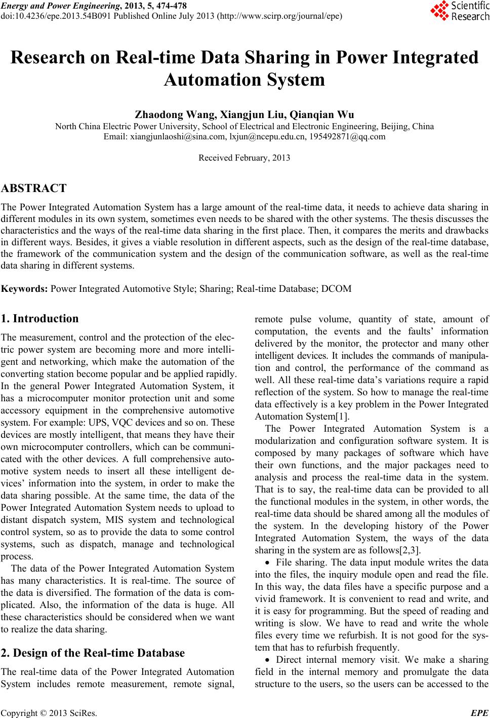 Energy and Power Engineering, 2013, 5, 474-478 doi:10.4236/epe.2013.54B091 Published Online July 2013 (http://www.scirp.org/journal/epe) Research on Real-time Data Sharing in Power Integrated Automation System Zhaodong Wang, Xiangjun Liu, Qianqian Wu North China Electric Power University, School of Electrical and Electronic Engineering, Beijing, Chi na Email: xiangjunlaoshi@sina.com, lxjun@ncepu.edu.cn, 195492871@qq.com Received February, 2013 ABSTRACT The Power Integrated Automation System has a large amount of the real-time data, it needs to achieve data sharing in different modules in its own system, sometimes even needs to be shared with the other systems. The thesis discusses the characteristics and the ways of the real-time data sharing in the first place. Then, it compares the merits and drawbacks in different ways. Besides, it gives a viable resolution in different aspects, such as the design of the real-time database, the framework of the communication system and the design of the communication software, as well as the real-time data sharing in different systems. Keywords: Power Integrated Automotive Style; Sharing; Real-time Database; DCOM 1. Introduction The measurement, control and the protection of the elec- tric power system are becoming more and more intelli- gent and networking, which make the automation of the converting station become popular and be applied rapidly. In the general Power Integrated Automation System, it has a microcomputer monitor protection unit and some accessory equipment in the comprehensive automotive system. For example: UPS, VQC devices and so on. These devices are mostly intelligent, that means they have their own microcomputer controllers, which can be communi- cated with the other devices. A full comprehensive auto- motive system needs to insert all these intelligent de- vices’ information into the system, in order to make the data sharing possible. At the same time, the data of the Power Integrated Automation System needs to upload to distant dispatch system, MIS system and technological control system, so as to provide the data to some control systems, such as dispatch, manage and technological process. The data of the Power Integrated Automation System has many characteristics. It is real-time. The source of the data is diversified. The formation of the data is com- plicated. Also, the information of the data is huge. All these characteristics should be considered when we want to realize the data sharing. 2. Design of the Real-time Database The real-time data of the Power Integrated Automation System includes remote measurement, remote signal, remote pulse volume, quantity of state, amount of computation, the events and the faults’ information delivered by the monitor, the protector and many other intelligent devices. It includes the commands of manipula- tion and control, the performance of the command as well. All these real-time data’s variations require a rapid reflection of the system. So how to manage the real-time data effectively is a key problem in the Power Integrated Automation System[1]. The Power Integrated Automation System is a modularization and configuration software system. It is composed by many packages of software which have their own functions, and the major packages need to analysis and process the real-time data in the system. That is to say, the real-time data can be provided to all the functional modules in the system, in other words, the real-time data should be shared among all the modules of the system. In the developing history of the Power Integrated Automation System, the ways of the data sha ring in the system are as follows[2,3]. File sharing. The data input module writes the data into the files, the inquiry module open and read the file. In this way, the data files have a specific purpose and a vivid framework. It is convenient to read and write, and it is easy for programming. But the speed of reading and writing is slow. We have to read and write the whole files every time we refurbish. It is not good for the sys- tem that has to refurbish frequently. Direct internal memory visit. We make a sharing field in the internal memory and promulgate the data structure to the users, so the users can be accessed to the Copyright © 2013 SciRes. EPE  Z. D. WANG ET AL. 475 internal memory to get the data. This way has a super speed, but it is complicated for programming. Even it will threaten the reliability of the system. Besides, it can not be visited through the Internet. Internet communication. We use the TCP/IP or UDP to pack and send the data. The speed of th is way is faster than the other ways, but there are binary data in the data packages, we need to know the data structures, and it is also complicated for programming. The biggest shortcoming of this way is not so extensible. Commercial database. With the development of the database technology, many databases can provide perfect data sharing and safety, and open widely. However, in the automotive system, the real-time data has many characteristics that are not fit for storage in the commercial data base, such as the data has an instantaneous effec- tiveness, the refurbish speed is fast, and the data forms are disunity and so on. Internal memory data base. Considering the features of the real-time data in automotive system, many manu- facturers have made the internal database used as the real-time database come true. All the data are stored in the internal memory, and the structure is flexible, the visit speed is also very fast. But in consideration with its openness, it is not as good as the commercial data base. According to the analysis of the above modes, we can see that it is a good choice to use the internal memory data base if we want to meet the need of the real-time of the Power Integrated Automation System. At the same time, in order to realize the open, steady data base, we need to provide standardized interfaces. After anatomiz- ing, the thesis uses the DCOM technology to realize the interface visit of the internal memory data base. COM is a subassembly standard of the Microsoft. It is an object model made up with component as the units, and it makes all kinds of software components have an interactive communication by one agreed mode. On one hand, the COM provides the interactive norms. On the other hand, it provides the interactive environment. The norms are not depended on any specially appointed languages, so COM is also a standard for different languages cooperated with each other to develop. DCOM is the extension of the COM. It can support mutual communication among different computers between the components and the client programmes, and these computers can be linked by WAN, LAN, even the Internet. As for client programmes, the locations of the component programmes are transparent, so there is no need to code for the remote process. By this token, it is perfect to choose DCOM technology to realize the real- time data sharing in the Power Integrated Automation System[4]. Considering all the factors, the design plan for the real-time database of the Power Integrated Automation System is provided. The real-time data are put in the internal memory with a differential form. As for the distribution of the internal memory, the real-time data are not belong to any application, it is used as an independent real-time data base to provide d igital services to the other applications. As for the realization of the client, the DCOM technology is selected to develop the intermediate layer of the database. In this way, we can ensure the security of the rea l-time da ta, and also s tand ard the interface to realize the distributed sharing. When all the modules visit the real-time data, they all need to use the unified intermediate layer’s components of the real-time data, so as to visit and operate the real-time data (including add- ing, revising, deleting and so on). At the same time, we need to testify the powers of the applications in the intermediate layer, so as to keep the data' security. The intermediate layer provides the ability of visiting the Internet. It is fit for the internet applications, and in this way can realize the data' distributed sharing[5]. The design of the real-time data base and its interface are showed as Figure 1. The DCOM components in the intermediate layer have already realized and applied in the Power Integrated Au to mation System in a larg e scale. The mode can meet the requirements of the data' real- time and open sharing features, and the application ef- fects are very ideal. 3. Input and Output of the Real-time Data Before you begin to format your paper, first write and save the content as a separate text file. Keep your text and graphic files separate until after the text has been formatted and styled. Do not use hard tabs, and limit use of hard returns to only one return at the end of a paragraph. Do not add any kind of pagination anywhere in the paper. Do not number text heads—the template will do that for you. In the Power Integrated Automation System, the real-time data communicates with the intel- ligent devices. By this way the data can input in the sys- tems or output to the distant dispatch systems. The input and the output of the real-time data base is the project to solve the communicatio n problems with the devices. Finally, complete content and organizational editing before formatting. Please take note of the following items when proofreading spelling and grammar: Figure 1. Real –time database and interface. Copyright © 2013 SciRes. EPE  Z. D. WANG ET AL. Copyright © 2013 SciRes. EPE 476 3.1. Design of the Communication Structure The host can communicate with the intelligent devices and get the data of the devices when link the intelligent devices and the computers with wires. The topological structure is star class structure. Its visit speed is fast, and the mode is flexible. The communication interface is the combination of the RS485 and Ethernet interface. The RS485 has highly reliability, and the communicate dis- tance is longer than one kilometre. Besides, the topo- logical structure can use the bus structure, which means in one wire we can link many devices with the RS485 interfaces. Recently, with the development of the tech- nology, many intelligent devices have the internet inter- faces, and the communicate medias are twisted pair (RJ45 interface) or optical fibre (fibre-optical interface). The Ethernet interface for communication has many ad- vantages, such as the high speed, the large data, and the communication is steady and reliable. So it is the ten- dency to use the Ethernet interface for communication in the Power Integrated Automation System. Our country made a standard agreement for the communication of the electrical equipment. There are two main parts: the CDT and the pooling. The agreement is the gather communi- cate experience during these years. The design is precise and reliable, and it is app lied widely into the Power Inte- grated Automation System. Almost all the complex automotive factories provide the interfaces for the stan- dard agreement. 3.2. Communication Solution According to the situation above, we should design a special subsystem in the Power Integrated Automation System, so as to communicate with the other intelligent equipment. The structure is showed as Figure 2. There designs a special computer for communication, it collects data from the intelligent equipment and transmits them into the Power Integrated Automation System. If there is not so many intelligent equipments insert, we can use the data acquisition unit of the system to replace it. We use the server, and use the Ethernet interface instead of RS485. The host links to the con- centrator and the switchboard. The topological structure is mainly used in the star class, and the part uses the bus structure. The communication wires with the Ethernet use the super 5 lines, and the other use the industrial shield twisted pair[6]. The solution is very convenient for connection, its configuration is flexible, and it is easy for expansion. Besides, when you add new intelligent equipments or upgrade the former equipments, it equals to adding or revising the nodes of the systems, and it has no impact on the integral structure of the system. 100MEthernet 485 network Communication host Multiport serial servers Power integrated automation system intelligent device Network witch and concentrator Remote control intelligent device intelligent device intelligent device intelligent device intelligent device intelligent device Figure 2. Structure of communication subsystem.  Z. D. WANG ET AL. 477 3.3. Design of the Communication Software There are so many communication modes and agree- ments for the intelligent equipments, many factories es- tablished the “agreement base” to solve the problems. They made a special communication module for each mode and agreement, so as to reuse them. But consider- ing the actual application effect, the number of the mod- ules in the “agreement base” is becoming larger and lar- ger, because many factories use the off standard agree- ments. And the purpose to reuse is failed, the repeating work gains too. It is a waste of labour. Considering all the situations above, we design a three-layer-software for communication, including communication layer, protocol layer and application layer. The design is shown as Fig- ure 3. The communication layer packages many working details of the normal communication interfaces, such as reading and writing, linking, setting up parameters, dealing with errors and so on. Also the layers above the communication layer don’t need to care about using what kind of interfaces. That is to say, the design realizes the irrelevant among the equipments. The protocol layer is in charge of organization and in- terpretation of the data. It is a translation machine to open and translate the data packets transfer from the communication layer, and transmits the data to the ap- plication layer. All the agreements can be into the two main types: CDT (Central Daylight Time) and Polling. It is also the most complicated part of the three-layer- software for communication, especially in dealing with the off standard agreements. The application layer manages the communication procedure with the intelligent equipments. Besides, it transmits the processing data to the real-time database and displays the data. The design of the three-layer-structure divides com- munication process into three segments, pick up the common characteristics from different communication ways, and it simplify the realization of the process. All the modules in the structure use the interface norms of the DCOM from the Microsoft and design each interchangeable process into a DCOM interface. Figure 3. The communication software structure. Take the Polling as an example, according to the de- sign idea of the DCOM interface, we make rules for the realization of the standard process and each key point, and define the interfaces shown as Table 1. The process of the Polling can be described like the following: loop detection-Listener response-data-Error retransmission-process data-repetitive execution. The three-layer-structure realizes the DCOM interface, normalizes the process and makes sure for the safety of the communication process. It also increases the reusing, decreases the repeated labour. It makes the production of the communication software into a package mode just like building blocks. As the producing tasks becoming larger and larger, the kinds of the intelligent equipments increasing, this me- thod has a lot of advantages. It is easy for batch produ- tion. It saves the debugging time with the intelligent equipments, and increases the w o r king efficiency. 4. Sharing of the Real-time Data in Different Systems After the text edit h as been completed, the paper is ready for the template. Duplicate the template file by using the Save As command, and use the naming convention prescribed by your journal for the name of your paper. In this newly created file, highlight all of the contents and import your prepared text file. You are now ready to style your paper. After using the DCOM technology to package the in- terface of visiting the real-time database, the real-time data can get the most convenient and direct way to share in different systems. Because the DCOM is a standard interface, if the other systems know the specific details of the interfaces, they can visit the real-time data just like the modules in the complex automotive system. Real- time data includes remote measurement, remote signal and amount of calculation, operating command, informa- tion fault and so on. Mean wh ile, the intermediate layer o f the real-time data base can standardize the interface of the real-time data, so as to visit and operate the data. Al- so the intermediate layer adds the function of the certi- fication authority of application programs, so as to make sure of the datas’ security. Besides, the intermediate Table 1. Define the interface. Item Define Loop detection data I Question Listener response I Listen Error retransmission I Redo Test the effectiveness of the data I Check Failure communication handling I After Error Process data I data Process Copyright © 2013 SciRes. EPE  Z. D. WANG ET AL. 478 Figure 4. Real-time data sharing system. layer provides the function of visiting the internet, so as to adjust to the application of the internet, and realizes the distributed data sharing. In this way, the system can satisfy the requirements of data’ real-time and open sharing, and the application effect is perfect. The Figure 4 shows the sharing of the real-time data in the system. There is a real-time data server for WEB service. It gets the data of the data base and provid es WEB services. In this way, any computer linked to it can get access to the data by the browser, and the relevant works are re- duced too. All the real-time data of th e complex automo- tive system, including the data of the intelligent equip- ments, can be made into pages according to the demands, and then open to the public. The managers can visit the working data of the system quickly as long as they link to the real-time data servers. This is an advantageous way for management and production. 5. Acknowledgements The research of the paper is sponsored by state key labo- ratory of alternate electrical power system with renew- able energy sources. We hereby express our thanks. REFERENCES [1] A. S. Malik, O. Boyko, N. Atkar and W. F. Young, “Real-time Manufacturing Database Architecture,” Con- trol Engineering, No. 8, 2004, pp. 147-175. [2] X. D. Huo, Y. L. Zhao and S. Q. Chen, “Processing in Mobile Distributed Real-time Data System,” Zhongnan University Academic Journal (Natural Science Version), Vol. 38, No. 12, 2007, pp. 1186-1191. [3] M. J. Lai, Y. S. Geng and G. G. Zhang, “The Research of Real-time Data Base in Converting Station Automatic Sys tem,” Relay, No. 1, 2006, pp. 66-69. [4] R. M. Li and X. Wang, “Application of the Real-time Data Base Technology in Industry Automatic System,” Proceedings of the 23rd Chinese Control Conference, 2004, pp. 1357-1361. [5] L. P. Nie, W. Y. Zhang and J. S. Xu, “Research and Ap- plication of the Distributed Isomerism Data Base Integra- tion Technology,” Heifei Technology University Aca- demic Journal (Natural Science Version), Vol. 29, No. 3, 2006, pp. 309-312. [6] W. L. Wang, D. R. Xu and W. F. Shao, “Research and Achievements of the Key Technology in Real-time Data Base of the Project Control System,” Microelectronics and Computer, No. 1, 2007, pp. 67-72. Copyright © 2013 SciRes. EPE |