Paper Menu >>
Journal Menu >>
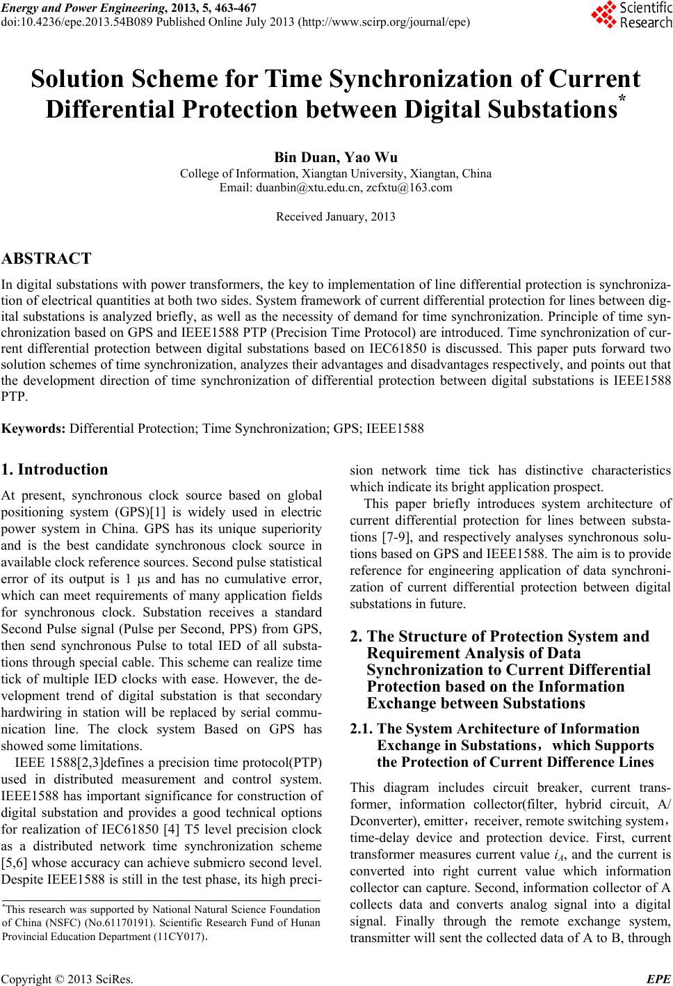 Energy and Power Engineering, 2013, 5, 463-467 doi:10.4236/epe.2013.54B089 Published Online July 2013 (http://www.scirp.org/journal/epe) Solution Scheme for Time Synchronization of Current Differential Protection between Digital Substations* Bin Duan, Yao Wu College of Information, Xiangtan University, Xiangtan, China Email: duanbin@xtu.edu.cn, zcfxtu@163.com Received January, 2013 ABSTRACT In digital substations with power transformers, the key to implementation of line differential protection is synchroniza- tion of electrical quantities at both two sides. System framework of current differential protection for lines between dig- ital substations is analyzed briefly, as well as the necessity of demand for time synchronization. Principle of time syn- chronization based on GPS and IEEE1588 PTP (Precision Time Protocol) are introduced. Time synchronization of cur- rent differential protection between digital substations based on IEC61850 is discussed. This paper puts forward two solution schemes of time synchronization, analyzes their advantages and disadvantages respectively, and points out that the development direction of time synchronization of differential protection between digital substations is IEEE1588 PTP. Keywords: Differential Protection; Time Synchronization; GPS; IEEE1588 1. Introduction At present, synchronous clock source based on global positioning system (GPS)[1] is widely used in electric power system in China. GPS has its unique superiority and is the best candidate synchronous clock source in available clock reference sources. Second pulse statistical error of its output is 1 μs and has no cumulative error, which can meet requirements of many application fields for synchronous clock. Substation receives a standard Second Pulse signal (Pulse per Second, PPS) from GPS, then send synchronous Pulse to total IED of all substa- tions through special cable. This scheme can realize time tick of multiple IED clocks with ease. However, the de- velopment trend of digital substation is that secondary hardwiring in station will be replaced by serial commu- nication line. The clock system Based on GPS has showed some limitations. IEEE 1588[2,3]defines a precision time protocol(PTP) used in distributed measurement and control system. IEEE1588 has important significance for construction of digital substation and provides a good technical options for realization of IEC61850 [4] T5 level precision clock as a distributed network time synchronization scheme [5,6] whose accuracy can achieve submicro second level. Despite IEEE1588 is still in the test phase, its high preci- sion network time tick has distinctive characteristics which indicate its bright application prospect. This paper briefly introduces system architecture of current differential protection for lines between substa- tions [7-9], and respectively analyses synchronous solu- tions based on GPS and IEEE1588. The aim is to provide reference for engineering application of data synchroni- zation of current differential protection between digital substations in future. 2. The Structure of Protection System and Requirement Analysis of Data Synchronization to Current Differential Protection based on the Information Exchange between Substations 2.1. The System Architecture of Information Exchange in Substations,which Supports the Protection of Current Difference Lines This diagram includes circuit breaker, current trans- former, information collector(filter, hybrid circuit, A/ Dconverter), emitter,receiver, remote switching system, time-delay device and protection device. First, current transformer measures current value iA, and the current is converted into right current value which information collector can capture. Second, information collector of A collects data and converts analog signal into a digital signal. Finally through the remote exchange system, transmitter will sent the collected data of A to B, through *This research was supported by National Natural Science Foundation of China (NSFC) (No.61170191). Scientific Research Fund of Hunan Provincial Education Department (11CY017). Copyright © 2013 SciRes. EPE 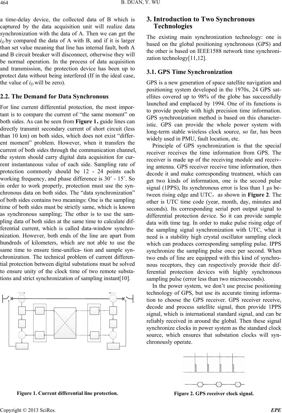 B. DUAN, Y. WU 464 a time-delay device, the collected data of B which is captured by the data acquisition unit will realize data synchronization with the data of A. Then we can get the iD by compared the data of A with B, and if it is larger than set value meaning that line has internal fault, both A and B circuit breaker will disconnect, otherwise they will be normal operation. In the process of data acquisition and transmission, the protection device has been up to protect data without being interfered (If in the ideal case, the value of iD will be zero). 2.2. The Demand for Data Synchronous For line current differential protection, the most impor- tant is to compare the current of “the same moment” on both sides. As can be seen from Figure 1,guide lines can directly transmit secondary current of short circuit (less than 10 km) on both sides, which does not exist “differ- ent moment” problem. However, when it transfers the current of both sides through the communication channel, the system should carry digital data acquisition for cur- rent instantaneous value of each side. Sampling rate of protection commonly should be 12 - 24 points each working frequency, and phase difference is 30˚ - 15˚. So in order to work properly, protection must use the syn- chronous data on both sides. The “data synchronization” of both sides contains two meanings: One is the sampling time of both sides must be strictly same, which is known as synchronous sampling; The other is to use the sam- pling data of both sides at the same time to calculate dif- ferential current, which is called data-window synchro- nization. However, both ends of the line are apart from hundreds of kilometers, which are not able to use the same time to ensure time-unifica- tion and sample syn- chronization. The technical problem of current differen- tial protection between digital substations must be solved to ensure unity of the clock time of two remote substa- tions and strict synchronization of sampling instant[10]. Figure 1. Current differential line protection. 3. Introduction to Two Synchronous Technologies The existing main synchronization technology: one is based on the global positioning synchronous (GPS) and the other is based on IEEE1588 network time synchroni- zation technology[11,12]. 3.1. GPS Time Synchronization GPS is a new generation of space satellite navigation and positioning system developed in the 1970s, 24 GPS sat- ellites covered up to 98% of the globe has successfully launched and emplaced by 1994. One of its functions is to provide people with high precision time information. GPS synchronization method is based on this character- istic. GPS can provide the whole power system with long-term stable wireless clock source, so far, has been widely used in PMU, fault location, etc. Principle of GPS synchronization is that the special receiver receives the time information from GPS. The receiver is made up of the receiving module and receiv- ing antenna. GPS receiver receive time information, then decode it and make corresponding treatment, which can get two kinds of information, one is the second pulse signal (1PPS), Its synchronous error is less than 1 μs be- tween rising edge and UTC,as shown in Figure 2. The other is UTC time code (year, month, day, minutes and seconds). Its corresponding serial port output signal to differential protection device. So it can provide sample data with time tag. In order to make pulse rising edge of the sampling signal synchronization with UTC, what it need is a stability high crystal oscillator sampling clock which can produces corresponding sampling pulse. IPPS synchronize the sampling pulse once per second. When two ends of line are equipped with this kind of synchro- nous receptors, they can respectively provide their dif- ferential protection devices with highly synchronous sampling pulse (error less than two microseconds). In the power system, we don’t use precise positioning technology of GPS, but use its accurate timing informa- tion to choose the GPS receiver. GPS receiver receive, decode and process satellite signal, then provide 1PPS signal, which is international standard signal, and can be reliably received in around the global. Then these signal synchronize clocks in power system as the standard clock source, which ensures that substation clocks will syn- chronously operate. Figure 2. GPS receiver clock signal. Copyright © 2013 SciRes. EPE 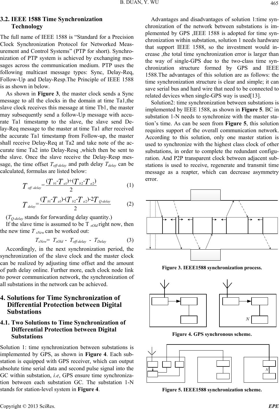 B. DUAN, Y. WU 465 3.2. IEEE 1588 Time Synchronization Technology The full name of IEEE 1588 is “Standard for a Precision Clock Synchronization Protocol for Networked Meas- urement and Control Systems” (PTP for short). Synchro- nization of PTP system is achieved by exchanging mes- sages across the communication medium. PTP uses the following multicast message types: Sync, Delay-Req, Follow-Up and Delay-Resp.The Principle of IEEE 1588 is as shown in below. As shown in Figure 3, the master clock sends a Sync message to all the clocks in the domain at time Ta1,the slave clock receives this message at time Tb1, the master may subsequently send a follow-Up message with accu- rate Ta1 timestamp to the slave, the slave send De- lay-Req message to the master at time Ta1 after received the accurate Ta1 timestamp from Follow-up, the master shall receive Delay-Req at Ta2 and take note of the ac- curate time Ta2 into Delay-Resq ,which then be sent to the slave. Once the slave receive the Delay-Resp mes- sage, the time offset Toff-delay and path delay Tdelay can be calculated, formulas are listed below: 112 2 - (-)+( - ) =2 bab a off delayTT TT T (1) 112 2- (-)-(- )-2 =2 babaQdelay delay TT TTT T (2) (TQ-delay stands for forwarding delay quantity.) If the slave time is assumed to be T sOld right now, then the new time T sNew can be worked out: TsNew= TsOld - Toff-delay - TDelay (3) Accordingly, in the next synchronization period, the synchronization of the slave clock and the master clock can be realized by adjusting time offset and the amount of path delay online. Further more, each clock node link to power communication network, the synchronization of all substations in the network can be achieved. 4. Solutions for Time Synchronization of Differential Protection between Digital Substations 4.1. Two Solutions to Time Synchronization of Differential Protection between Digital Substations Solution 1: time synchronization between substations is implemented by GPS, as shown in Figure 4. Each sub- station is equipped with GPS receiver, which can output absolute time serial data and second pulse signal into the GC within substation, i.e, GPS ensure time synchroniza- tion between each substation GC. The substation 1-N stands for station-level system in Figure 4. Advantages and disadvantages of solution 1:time syn- chronization of the network between substations is im- plemented by GPS ,IEEE 1588 is adopted for time syn- chronization within substation, solution 1 needs hardware that support IEEE 1588, so the investment would in- crease ,the total time synchronization error is larger than the way of single-GPS due to the two-class time syn- chronization structure formed by GPS and IEEE 1588.The advantages of this solution are as follows: the time synchronization structure is clear and simple; it can save serial bus and hard wire that need to be connected to related devices when single-GPS way is used[13]. Solution2: time synchronization between substations is implemented by IEEE 1588, as shown in Figure 5. BC in substation 1-N needs to synchronize with the master sta- tion’s time. As can be seen from Figure 5, this solution requires support of the overall communication network. According to this solution, only one master station is used to synchronize with the highest class clock of other substations, in order to complete the redundant configu- ration. And P2P transparent clock between adjacent sub- stations is used to receive, regenerate and transmit time message as a reapter, which can decrease asymmetry error. Figure 3. IEEE1588 synchronization process. N Figure 4. GPS synchronous scheme. N Figure 5. IEEE1588 synchronization scheme. Copyright © 2013 SciRes. EPE 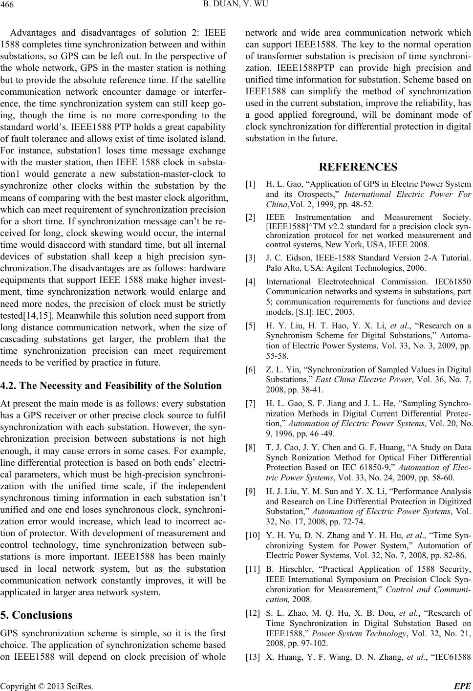 B. DUAN, Y. WU 466 Advantages and disadvantages of solution 2: IEEE 1588 completes time synchronization between and within substations, so GPS can be left out. In the perspective of the whole network, GPS in the master station is nothing but to provide the absolute reference time. If the satellite communication network encounter damage or interfer- ence, the time synchronization system can still keep go- ing, though the time is no more corresponding to the standard world’s. IEEE1588 PTP holds a great capability of fault tolerance and allows exist of time isolated island. For instance, substation1 loses time message exchange with the master station, then IEEE 1588 clock in substa- tion1 would generate a new substation-master-clock to synchronize other clocks within the substation by the means of comparing with the best master clock algorithm, which can meet requirement of synchronization precision for a short time. If synchronization message can’t be re- ceived for long, clock skewing would occur, the internal time would disaccord with standard time, but all internal devices of substation shall keep a high precision syn- chronization.The disadvantages are as follows: hardware equipments that support IEEE 1588 make higher invest- ment, time synchronization network would enlarge and need more nodes, the precision of clock must be strictly tested[14,15]. Meanwhile this solution need support from long distance communication network, when the size of cascading substations get larger, the problem that the time synchronization precision can meet requirement needs to be verified by practice in future. 4.2. The Necessity and Feasibility of the Solution At present the main mode is as follows: every substation has a GPS receiver or other precise clock source to fulfil synchronization with each substation. However, the syn- chronization precision between substations is not high enough, it may cause errors in some cases. For example, line differential protection is based on both ends’ electri- cal parameters, which must be high-precision synchroni- zation with the unified time scale, if the independent synchronous timing information in each substation isn’t unified and one end loses synchronous clock, synchroni- zation error would increase, which lead to incorrect ac- tion of protector. With development of measurement and control technology, time synchronization between sub- stations is more important. IEEE1588 has been mainly used in local network system, but as the substation communication network constantly improves, it will be applicated in larger area network system. 5. Conclusions GPS synchronization scheme is simple, so it is the first choice. The application of synchronization scheme based on IEEE1588 will depend on clock precision of whole network and wide area communication network which can support IEEE1588. The key to the normal operation of transformer substation is precision of time synchroni- zation. IEEE1588PTP can provide high precision and unified time information for substation. Scheme based on IEEE1588 can simplify the method of synchronization used in the current substation, improve the reliability, has a good applied foreground, will be dominant mode of clock synchronization for differential protection in digital substation in the future. REFERENCES [1] H. L. Gao, “Application of GPS in Electric Power System and its Orospects,” International Electric Power For China,Vol. 2, 1999, pp. 48-52. [2] IEEE Instrumentation and Measurement Society. [IEEE1588]^TM v2.2 standard for a precision clock syn- chronization protocol for net worked measurement and control systems, New York, USA, IEEE 2008. [3] J. C. Eidson, IEEE-1588 Standard Version 2-A Tutorial. Palo Alto, USA: Agilent Technologies, 2006. [4] International Electrotechnical Commission. IEC61850 Communication networks and systems in substations, part 5; communication requirements for functions and device models. [S.I]: IEC, 2003. [5] H. Y. Liu, H. T. Hao, Y. X. Li, et al., “Research on a Synchronism Scheme for Digital Substations,” Automa- tion of Electric Power Systems, Vol. 33, No. 3, 2009, pp. 55-58. [6] Z. L. Yin, “Synchronization of Sampled Values in Digital Substations,” East China Electric Power, Vol. 36, No. 7, 2008, pp. 38-41. [7] H. L. Gao, S. F. Jiang and J. L. He, “Sampling Synchro- nization Methods in Digital Current Differential Protec- tion,” Automation of Electric Power Systems, Vol. 20, No. 9, 1996, pp. 46 -49. [8] T. J. Cao, J. Y. Chen and G. F. Huang, “A Study on Data Synch Ronization Method for Optical Fiber Differential Protection Based on IEC 61850-9,” Automation of Elec- tric Power Systems, Vol. 33, No. 24, 2009, pp. 58-60. [9] H. J. Liu, Y. M. Sun and Y. X. Li, “Performance Analysis and Research on Line Differential Protection in Digitized Substation,” Automation of Electric Power Systems, Vol. 32, No. 17, 2008, pp. 72-74. [10] Y. H. Yu, D. N. Zhang and Y. H. Hu, et al., “Time Syn- chronizing System for Power System,” Automation of Electric Power Systems, Vol. 32, No. 7, 2008, pp. 82-86. [11] B. Hirschler, “Practical Application of 1588 Security, IEEE International Symposium on Precision Clock Syn- chronization for Measurement,” Control and Communi- cation, 2008. [12] S. L. Zhao, M. Q. Hu, X. B. Dou, et al., “Research of Time Synchronization in Digital Substation Based on IEEE1588,” Power System Technology, Vol. 32, No. 21, 2008, pp. 97-102. [13] X. Huang, Y. F. Wang, D. N. Zhang, et al., “IEC61588 Copyright © 2013 SciRes. EPE  B. DUAN, Y. WU Copyright © 2013 SciRes. EPE 467 Time Synchronization System and Security Evaluation for Smart Substations,” Automation of Electric Power Systems, Vol. 36, No. 13, 2012, pp. 76-80. [14] R. F. Li, X. J. Zeng, Z. W. Li, et al., “Analysis and Cor- rection Methods for Network Time-delay Error of IEEE1588 Synchronization Clock,” Automation of Elec- tric Power Systems, Vol. 36, No. 12, 2012, pp. 82-87. [15] D. S. Mohl, “IEEE1588-Precise Time Synchronization as the Basis for Real Time Applications in Automation,” Industrial Networking Solution, 2003. |