Paper Menu >>
Journal Menu >>
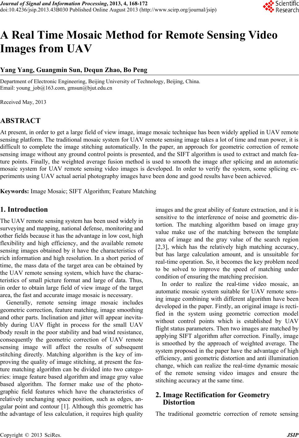 Journal of Signal and Information Processing, 2013, 4, 168-172 doi:10.4236/jsip.2013.43B030 Published Online August 2013 (http://www.scirp.org/journal/jsip) A Real Time Mosaic Method for Remote Sensing Video Images from UAV Yang Yang, Guangmin Sun, Dequn Zhao, Bo Peng Department of Electronic Engineering, Beijing University of Technology, Beijing, China. Email: young_job@163.com, gmsun@bjut.edu.cn Received May, 2013 ABSTRACT At present, in order to get a large field of view image, image mosaic technique has been widely applied in UAV remote sensing platform. The traditional mosaic system for UAV remote sensing image takes a lot of time and man power, it is difficult to complete the image stitching automatically. In the paper, an approach for geometric correction of remote sensing image without any ground control points is presented, and the SIFT algorithm is used to extract and match fea- ture points. Finally, the weighted average fusion method is used to smooth the image after splicing and an automatic mosaic system for UAV remote sensing video images is developed. In order to verify the system, some splicing ex- periments using UAV actual aerial photography images have been done and good results have been achieved. Keywords: Image Mosaic; SIFT Algorithm; Feature Matching 1. Introduction The UAV remote sensing system has been used widely in surveying and mapping, national defense, monitoring and other fields because it has the advantage in low cost, high flexibility and high efficiency, and the available remote sensing images obtained by it have the characteristics of rich information and high resolution. In a short period of time, the mass data of the target area can be obtained by the UAV remote sensing system, which have the charac- teristics of small picture format and large of data. Thus, in order to obtain large field of view image of the target area, the fast and accurate image mosaic is necessary. Generally, remote sensing image mosaic includes geometric correction, feature matching, image smoothing and other parts. Inclination and jitter will appear inevita- bly during UAV flight in process for the small UAV body result in the poor stability and bad wind resistance, consequently the geometric correction of UAV remote sensing image will affect the results of subsequent stitching directly. Matching algorithm is the key of im- proving the quality of image stitching, at present the fea- ture matching algorithm can be divided into two catego- ries: image feature based algorithm and image gray value based algorithm. The former make use of the photo- graphic field features which have the characteristics of relatively unchanging space position, such as edges, an- gular point and contour [1]. Although this geometric has the advantage of less calculation, it requires high quality images and the great ability of feature extraction, and it is sensitive to the interference of noise and geometric dis- tortion. The matching algorithm based on image gray value make use of the matching between the template area of image and the gray value of the search region [2,3], which has the relatively high matching accuracy, but has large calculation amount, and is unsuitable for real-time operation. So, it becomes the key problem need to be solved to improve the speed of matching under condition of ensuring the matching precision. In order to realize the real-time video mosaic, an automatic mosaic system suitable for UAV remote sens- ing image combining with different algorithm have been developed in the paper. Firstly, an original image is recti- fied in the system using geometric correction model without control points which is established by UAV flight status parameters. Then two images are matched by applying SIFT algorithm after correction. Finally, image is smoothed by the approach of weighted average. The system proposed in the paper have the advantage of high efficiency, anti geometric distortion and anti illumination change, which can realize the real-time dynamic mosaic of the remote sensing video images and ensure the stitching accuracy at the same time. 2. Image Rectification for Geometry Distortion The traditional geometric correction of remote sensing Copyright © 2013 SciRes. JSIP 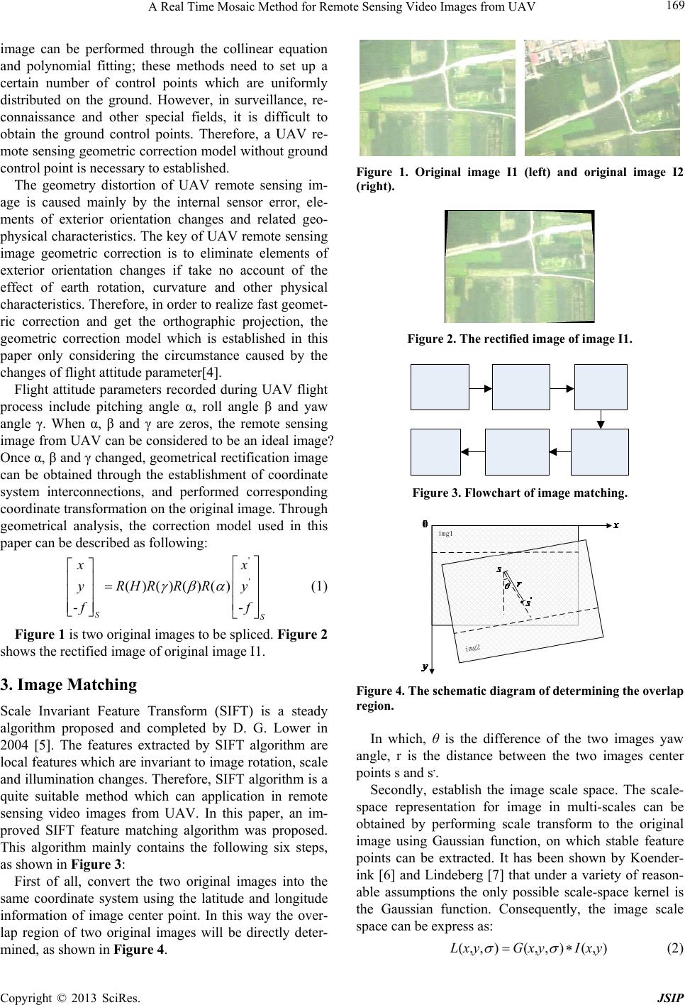 A Real Time Mosaic Method for Remote Sensing Video Images from UAV 169 image can be performed through the collinear equation and polynomial fitting; these methods need to set up a certain number of control points which are uniformly distributed on the ground. However, in surveillance, re- connaissance and other special fields, it is difficult to obtain the ground control points. Therefore, a UAV re- mote sensing geometric correction model without ground control point is necessary to established. The geometry distortion of UAV remote sensing im- age is caused mainly by the internal sensor error, ele- ments of exterior orientation changes and related geo- physical characteristics. The key of UAV remote sensing image geometric correction is to eliminate elements of exterior orientation changes if take no account of the effect of earth rotation, curvature and other physical characteristics. Therefore, in order to realize fast geomet- ric correction and get the orthographic projection, the geometric correction model which is established in this paper only considering the circumstance caused by the changes of flight attitude parameter[4]. Flight attitude parameters recorded during UAV flight process include pitching angle α, roll angle β and yaw angle γ. When α, β and γ are zeros, the remote sensing image from UAV can be considered to be an ideal image? Once α, β and γ changed, geometrical rectification image can be obtained through the establishment of coordinate system interconnections, and performed corresponding coordinate transformation on the original image. Through geometrical analysis, the correction model used in this paper can be described as following: ' ' ()()()() -- SS x x yRHRRRy f f (1) Figure 1 is two original images to be spliced. Figure 2 shows the rectified image of original image I1. 3. Image Matching Scale Invariant Feature Transform (SIFT) is a steady algorithm proposed and completed by D. G. Lower in 2004 [5]. The features extracted by SIFT algorithm are local features which are invariant to image rotation, scale and illumination changes. Therefore, SIFT algorithm is a quite suitable method which can application in remote sensing video images from UAV. In this paper, an im- proved SIFT feature matching algorithm was proposed. This algorithm mainly contains the following six steps, as shown in Figure 3: First of all, convert the two original images into the same coordinate system using the latitude and longitude information of image center point. In this way the over- lap region of two original images will be directly deter- mined, as shown in Figure 4. Figure 1. Original image I1 (left) and original image I2 (right). Figure 2. The rectified image of image I1. Figure 3. Flowchart of image matching. Figure 4. The schematic diagram of determinin g th e overlap region. In which, θ is the difference of the two images yaw angle, r is the distance between the two images center points s and s,. Secondly, establish the image scale space. The scale- space representation for image in multi-scales can be obtained by performing scale transform to the original image using Gaussian function, on which stable feature points can be extracted. It has been shown by Koender- ink [6] and Lindeberg [7] that under a variety of reason- able assumptions the only possible scale-space kernel is the Gaussian function. Consequently, the image scale space can be express as: (,, )(,, )(,)LxyGxy Ixy (2) Copyright © 2013 SciRes. JSIP 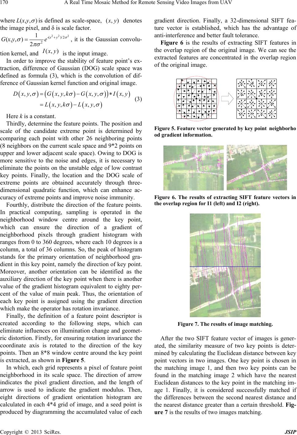 A Real Time Mosaic Method for Remote Sensing Video Images from UAV 170 where (,, )Lxy is defined as scale-space, (, ) x y denotes the image pixel, and δ is scale factor. 22 2 -()/ 2 2 1 (,, )2 xy Gxy e , it is the Gaussian convolu- tion kernel, and is the input image. ),( yxI In order to improve the stability of feature point’s ex- traction, difference of Gaussian (DOG) scale space was defined as formula (3), which is the convolution of dif- ference of Gaussian kernel function and original image. ,,,,,, , ,, ,, D xyG xykG xyIxy Lxyk Lxy (3) Here k is a constant. Thirdly, determine the feature points. The position and scale of the candidate extreme point is determined by comparing each point with other 26 neighboring points (8 neighbors on the current scale space and 9*2 points on upper and lower adjacent scale space). Owing to DOG is more sensitive to the noise and edges, it is necessary to eliminate the points on the unstable edge of low contrast key points. Finally, the location and the DOG scale of extreme points are obtained accurately through three- dimensional quadratic function, which can enhance ac- curacy of extreme points and improve noise immunity. Fourthly, distribute the direction of the feature points. In practical computing, sampling is operated in the neighborhood window centre around the key point, which can ensure the direction of a gradient of neighborhood pixels through gradient histogram with ranges from 0 to 360 degrees, where each 10 degrees is a column, a total of 36 columns. So, the peak of histogram stands for the primary orientation of neighborhood gra- dient in this key point, namely the direction of key point. Moreover, another orientation can be identified as the auxiliary direction of the key point when there is another value of the gradient histogram equivalent to eighty per- cent of the value of main peak. Thus, the orientation of each key point is assigned using the gradient direction which make the operator has rotation invariance. Finally, the definition of a feature point descriptor is created according to the following steps, which can eliminate influences on illumination change and geomet- ric distortion. Firstly, for ensuring rotation invariance the coordinate axis is rotated to the direction of the key points. Then an 8*8 window centre around the key point is extracted, as shown in Figure 5. In which, each grid represents a pixel of feature point neighborhood in its scale space. The direction of arrow indicates the pixel gradient direction, and the length of arrow is used to indicate the gradient modulus. Then, eight directions of gradient orientation histogram are calculated in each 4*4 grid of image, and a seed point is produced by diagramming the accumulated value of each gradient direction. Finally, a 32-dimensional SIFT fea- ture vector is established, which has the advantage of anti-interference and better fault tolerance. Figure 6 is the results of extracting SIFT features in the overlap region of the original image. We can see the extracted features are concentrated in the overlap region of the original image. Figure 5. Feature vector generated by key pointneighborho od gradient information. Figure 6. The results of extracting SIFT feature vectors in the overlap region for I1 (left) and I2 (right). Figure 7. The results of image matching. After the two SIFT feature vector of images is gener- ated, the similarity measure of two key points is deter- mined by calculating the Euclidean distance between key point vectors in two images. One key point is chosen in the matching image 1, and then two key points can be found in the matching image 2 which have the nearest Euclidean distances to the key point in the matching im- age 1. Finally, it is considered successfully matched if the differences between the second nearest distance and the nearest distance greater than a certain threshold. Fig- ure 7 is the results of two images matching. Copyright © 2013 SciRes. JSIP 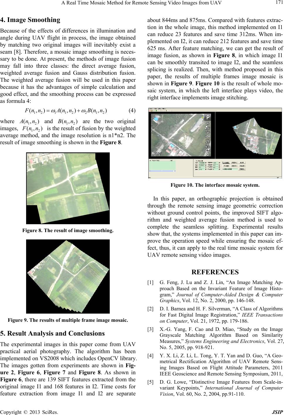 A Real Time Mosaic Method for Remote Sensing Video Images from UAV 171 4. Image Smoothing Because of the effects of differences in illumination and angle during UAV flight in process, the image obtained by matching two original images will inevitably exist a seam [8]. Therefore, a mosaic image smoothing is neces- sary to be done. At present, the methods of image fusion may fall into three classes: the direct average fusion, weighted average fusion and Gauss distribution fusion. The weighted average fusion will be used in this paper because it has the advantages of simple calculation and good effect, and the smoothing process can be expressed as formula 4: 121 122 12 (, )(, )(, ) F nnAnn Bnn (4) where 12 (, ) A nn (, and 12 are the two original images, 12 (, )Bn n ) F nn is the result of fusion by the weighted average method, and the image resolution is n1*n2. The result of image smoothing is shown in the Figure 8. Figure 8. The result of image smoothing. Figure 9. The results of multiple frame image mosaic. 5. Result Analysis and Conclusions The experimental images in this paper come from UAV practical aerial photography. The algorithm has been implemented on VS2008 which includes OpenCV library. The images gotten from experiments are shown in Fig- ure 2, Figure 6, Figure 7 and Figure 8. As shown in Figure 6, there are 139 SIFT features extracted from the original image I1 and 168 features in I2. Time costs for feature extraction from image I1 and I2 are separate about 844ms and 875ms. Compared with features extrac- tion in the whole image, this method implemented on I1 can reduce 23 features and save time 312ms. When im- plemented on I2, it can reduce 212 features and save time 625 ms. After feature matching, we can get the result of image fusion, as shown in Figure 8, in which image I1 can be smoothly transited to image I2, and the seamless splicing is realized. Then, with method proposed in this paper, the results of multiple frames image mosaic is shown in Figure 9. Figure 10 is the result of whole mo- saic system, in which the left interface plays video, the right interface implements image stitching. Figure 10. The interface mosaic system. In this paper, an orthographic projection is obtained through the remote sensing image geometric correction without ground control points, the improved SIFT algo- rithm and weighted average fusion method is used to complete the seamless splitting. Experimental results show that, the systems implemented in this paper can im- prove the operation speed while ensuring the mosaic ef- fect, thus, it can apply to the real time mosaic system for UAV remote sensing video images. REFERENCES [1] G. Feng, J. Lu and Z. J. Lin, “An Image Matching Ap- proach Based on the Invariant Feature of Image Histo- gram,” Journal of Computer-Aided Design & Computer Graphics, Vol. 12, No. 2, 2000, pp. 146-148. [2] D. I. Barnea and H. F. Silverman, “A Class of Algorithms for Fast Digital Image Registration,” IEEE Transactions on Computer, Vol. 21, 1972, pp. 179-186. [3] X.-G. Yang, F. Cao and D. Miao, “Study on the Image Grayscale Matching Algorithm Based on Similarity Measures,” Systems Engineering and Electronics, Vol. 27, No. 5, 2005, pp. 918-921. [4] Y. X. Li, Z. Li, L. Tong, Y. T. Yan and D. Guo, “A Geo- metrical Rectification Algorithm of UAV Remote Sens- ing Images Based on Flight Attitude Parameters, 2011 IEEE Geoscience and Remote Sensing Symposium, 2011, [5] D. G. Lowe, “Distinctive Image Features from Scale-in- variant Keypoints,” International Journal of Computer Vision, Vol. 60, No. 2, 2004, pp.91-110. Copyright © 2013 SciRes. JSIP  A Real Time Mosaic Method for Remote Sensing Video Images from UAV Copyright © 2013 SciRes. JSIP 172 [6] J. J. Koenderink, “The Structure of Images,” Biological Cybernetics, Vol. 50, No. 5, 1984, pp. 363-370. [7] T. Lindeberg, “Scale-Space Theory: A Basic Tool for Analyzing Structures at Different Scales,” Journal of Ap- plied Statistics, Vol. 21, No. 2, pp. 224-270. [8] S. L. Zhu, Z. B. Z. Qian, “The Seam-line Removal under Mosaicking of Remote Sensing Images,” Journal of Re- mote Sensing, Vol. 6, No. 3, 2002, pp. 183-187. |