Xilinx System Generator® Based Implementation of a Novel Method of Extraction of Nonstationary Sinusoids
8
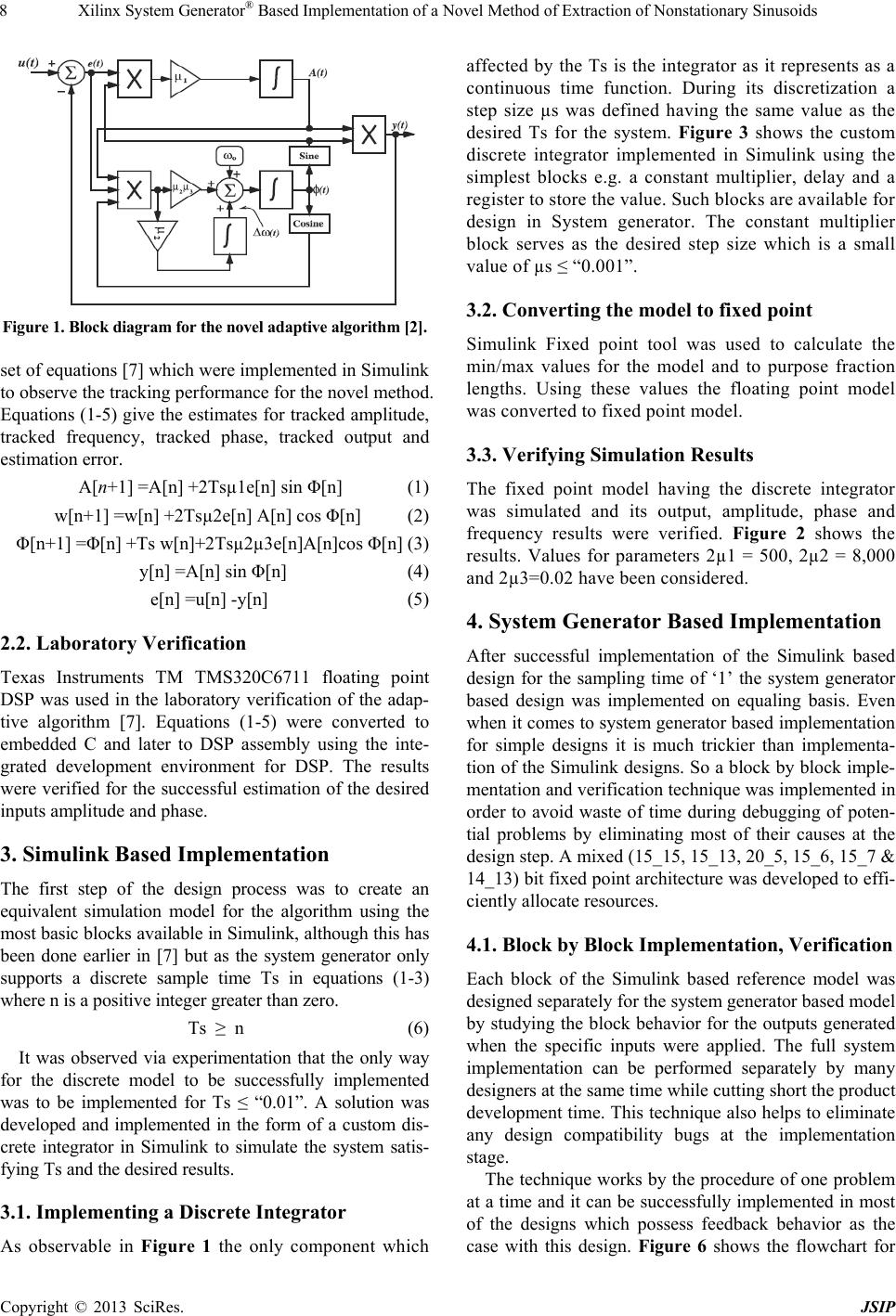
Figure 1. Block diagram for the novel adaptive algorithm [2].
set of equations [7] which were implemented in Simulink
to observe the tracking performance for the novel method.
Equations (1-5) give the estimates for tracked amplitude,
tracked frequency, tracked phase, tracked output and
estimation error.
A[n+1] =A[n] +2Tsµ1e[n] sin Φ[n] (1)
w[n+1] =w[n] +2Tsµ2e[n] A[n] cos Φ[n] (2)
Φ[n+1] =Φ[n] +Ts w[n]+2Tsµ2µ3e[n]A[n]cos Φ[n] (3)
y[n] =A[n] sin Φ[n] (4)
e[n] =u[n] -y[n] (5)
2.2. Laboratory Verification
Texas Instruments TM TMS320C6711 floating point
DSP was used in the laboratory verification of the adap-
tive algorithm [7]. Equations (1-5) were converted to
embedded C and later to DSP assembly using the inte-
grated development environment for DSP. The results
were verified for the successful estimation of the desired
inputs amplitude and phase.
3. Simulink Based Implementation
The first step of the design process was to create an
equivalent simulation model for the algorithm using the
most basic blocks available in Simulink, although this has
been done earlier in [7] but as the system generator only
supports a discrete sample time Ts in equations (1-3)
where n is a positive integer greater than zero.
Ts ≥ n (6)
It was observed via experimentation that the only way
for the discrete model to be successfully implemented
was to be implemented for Ts ≤ “0.01”. A solution was
developed and implemented in the form of a custom dis-
crete integrator in Simulink to simulate the system satis-
fying Ts and the desired results.
3.1. Implementing a Discrete Integrator
As observable in Figure 1 the only component which
affected by the Ts is the integrator as it represents as a
continuous time function. During its discretization a
step size µs was defined having the same value as the
desired Ts for the system. Figure 3 shows the custom
discrete integrator implemented in Simulink using the
simplest blocks e.g. a constant multiplier, delay and a
register to store the value. Such blocks are available for
design in System generator. The constant multiplier
block serves as the desired step size which is a small
value of µs ≤ “0.001”.
3.2. Converting the model to fixed point
Simulink Fixed point tool was used to calculate the
min/max values for the model and to purpose fraction
lengths. Using these values the floating point model
was converted to fixed point model.
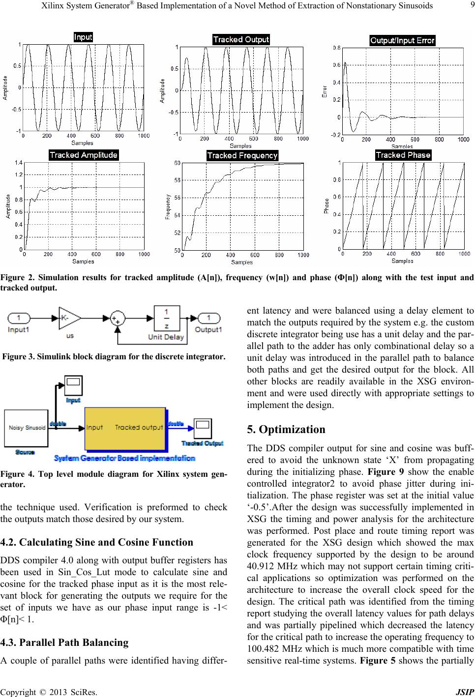
3.3. Verifying Simulation Results
The fixed point model having the discrete integrator
was simulated and its output, amplitude, phase and
frequency results were verified. Figure 2 shows the
results. Values for parameters 2µ1 = 500, 2µ2 = 8,000
and 2µ3=0.02 have been considered.
4. System Generator Based Implementation
After successful implementation of the Simulink based
design for the sampling time of ‘1’ the system generator
based design was implemented on equaling basis. Even
when it comes to system generator based implementation
for simple designs it is much trickier than implementa-
tion of the Simulink designs. So a block by block imple-
mentation and verification technique was implemented in
order to avoid waste of time during debugging of poten-
tial problems by eliminating most of their causes at the
design step. A mixed (15_15, 15_13, 20_5, 15_6, 15_7 &
14_13) bit fixed point architecture was developed to effi-
ciently allocate resources.
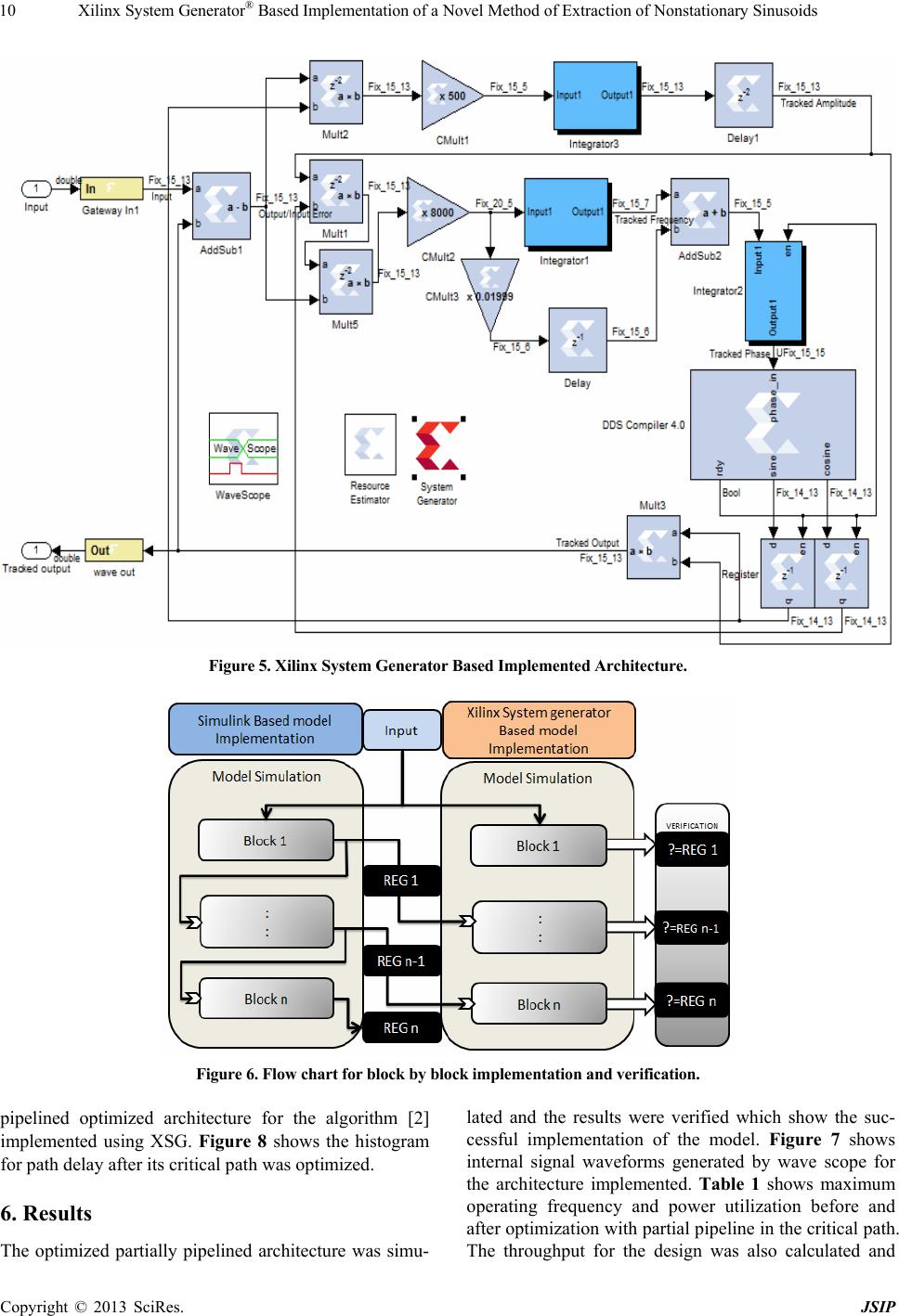
4.1. Block by Block Implementation, Verification
Each block of the Simulink based reference model was
designed separately for the system generator based model
by studying the block behavior for the outputs generated
when the specific inputs were applied. The full system
implementation can be performed separately by many
designers at the same time while cutting short the product
development time. This technique also helps to eliminate
any design compatibility bugs at the implementation
stage.
The technique works by the procedure of one problem
at a time and it can be successfully implemented in most
of the designs which possess feedback behavior as the
case with this design. Figure 6 shows the flowchart for
Copyright © 2013 SciRes. JSIP