Paper Menu >>
Journal Menu >>
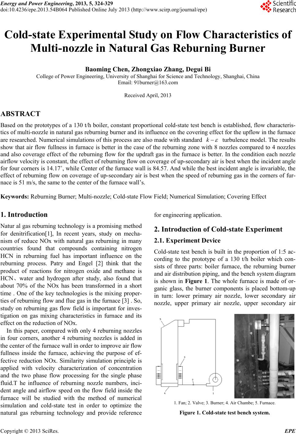 Energy and Power Engineering, 2013, 5, 324-329 doi:10.4236/epe.2013.54B064 Published Online July 2013 (http://www.scirp.org/journal/epe) Cold-state Experimental Study on Flow Characteristics of Multi-nozzle in Natural Gas Reburning Burner Baoming Chen, Zhongxiao Zhang, Degui Bi College of Power Engineering, University of Shanghai for Science and Technology, Shanghai, China Email: 91burner@163.com Received April, 2013 ABSTRACT Based on the prototypes of a 130 t/h boiler, constant proportional cold-state test bench is established, flow characteris- tics of multi-nozzle in natural gas reburning burner and its influence on the covering effect for the upflow in the furnace are researched. Numerical simulations of this process are also made with standard k turbulence model. The results show that air flow fullness in furnace is better in the case of the reburning zone with 8 nozzles compared to 4 nozzles and also coverage effect of the reburning flow for the updraft gas in the furnace is better. In the condition each nozzle airflow velocity is constant, the effect of reburning flow on coverage of up-secondary air is best when the incident angle for four corners is 14.17˚, while Center of the furnace wall is 84.57. And while the best incident angle is invariable, the effect of reburning flow on coverage of up-secondary air is best when the speed of reburning gas in the corners of fur- nace is 51 m/s, the same to the center of the furnace wall’s. Keywords: Reburning Burner; Multi-nozzle; Cold-state Flow Field; Numerical Simulation; Covering Effect 1. Introduction Natur al gas reburning technology is a promising method for denitrification[1], In recent years, study on mecha- nism of reduce NOx with natural gas reburning in many countries found that compounds containing nitrogen HCN in reburning fuel has important influence on the reburning process. Patry and Engel [2] think that the product of reactions for nitrogen oxide and methane is HCN、water and hydrogen after study, also found that about 70% of the NOx has been transformed in a short time . One of the key technologies is the mixing proper- ties of reburning flow and flue gas in the furnace [3] . So, study on reburning gas flow field is important for inves- tigation on gas mixing characteristics in furnace and its effect on the reduction of NOx. In this paper, compared with only 4 reburning nozzles in four corners, another 4 reburning nozzles is added in the center of the furnace wall in order to improve air flow fullness inside the furnace, achieving the purpose of ef- fective reduction NOx. Similarity simulation principle is applied with velocity characterization of concentration and the two phase flow processing for the single phase fluid.T he influence of reburning nozzle numbers, inci- dent angle and airflow speed on the flow field inside the furnace will be studied with the method of numerical simulation and cold-state test in order to optimize the natural gas reburning technology and provide reference for engineering application. 2. Introduction of Cold-state Experiment 2.1. Experiment Device Cold-state test bench is built in the proportion of 1:5 ac- cording to the prototype of a 130 t/h boiler which con- sists of three parts: boiler furnace, the reburning burner and air distribution piping, and the bench system diagram is shown in Figure 1. The whole furnace is made of or- ganic glass, the burner components is placed bottom-up in turn: lower primary air nozzle, lower secondary air nozzle, upper primary air nozzle, upper secondary air 1. Fan; 2. Valve; 3. Burner; 4. Air Chambe; 5. Furnace. Figure 1. Cold-state test bench system. Copyright © 2013 SciRes. EPE 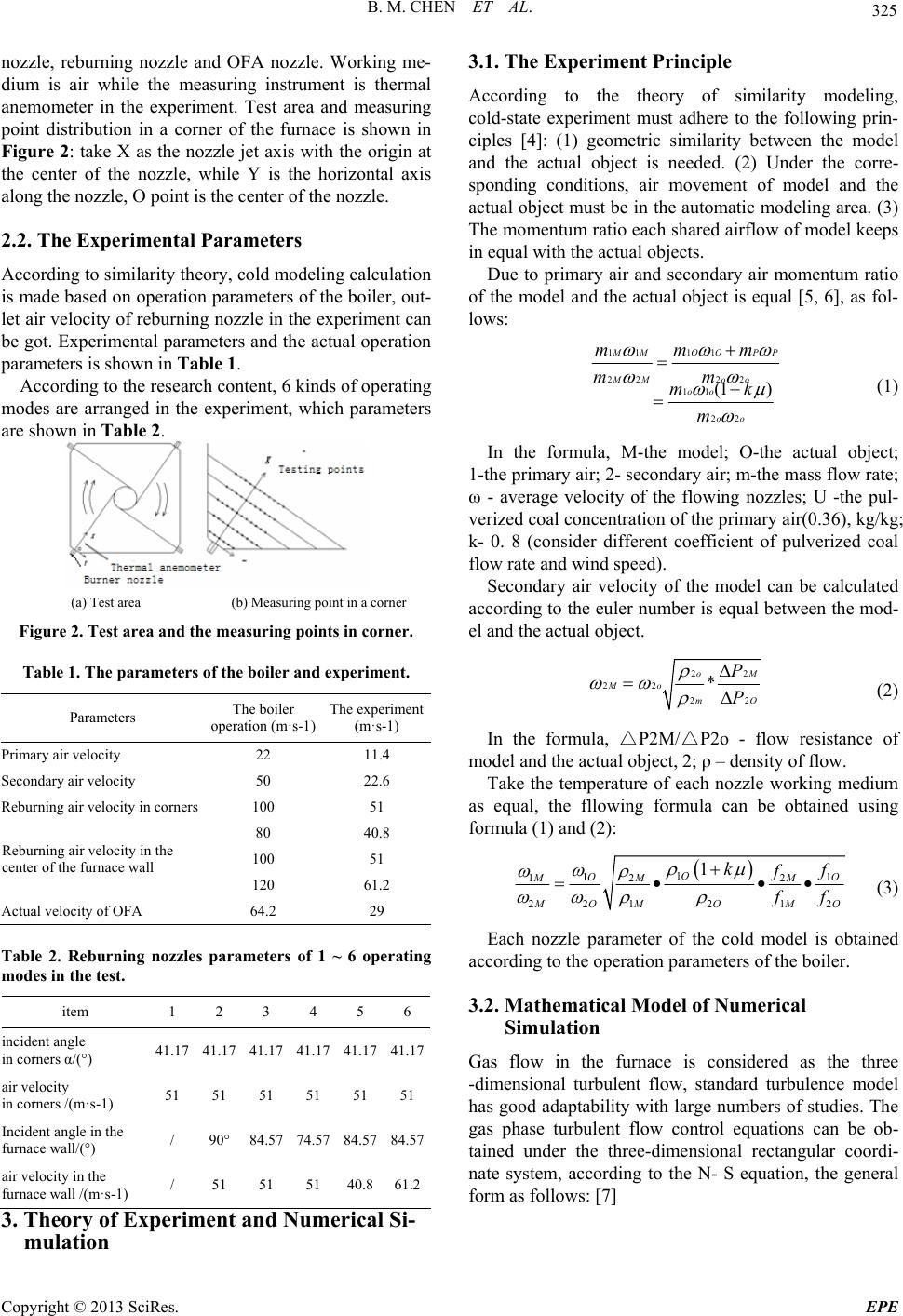 B. M. CHEN ET AL. 325 nozzle, reburning nozzle and OFA nozzle. Working me- dium is air while the measuring instrument is thermal anemometer in the experiment. Test area and measuring point distribution in a corner of the furnace is shown in Figure 2: take X as the nozzle jet axis with the origin at the center of the nozzle, while Y is the horizontal axis along the nozzle, O point is the center of the nozzle. 2.2. The Experimental Parameters According to similarity theory, cold modeling calculation is made based on operation parameters of the boiler, out- let air velocity of reburning nozzle in the experiment can be got. Experimental parameters and the actual operation parameters is shown in Table 1. According to the research content, 6 kinds of operating modes are arranged in the experiment, which parameters are shown in Table 2. (a) Test area (b) Measuring point in a corner Figure 2. Test area and the measuring points in corner. Table 1. The parameters of the boiler and experiment. Parameters The boiler operation (m·s-1) The experiment (m·s-1) Primary air velocity 22 11.4 Secondary air velocity 50 22.6 Reburning air velocity in corners 100 51 80 40.8 100 51 Reburning air velocity in the center of the furnace wall 120 61.2 Actual velocity of OFA 64.2 29 Table 2. Reburning nozzles parameters of 1 ~ 6 operating modes in the test. item 1 2 3 4 5 6 incident angle in corners α/(°) 41.17 41.17 41.17 41.17 41.17 41.17 air velocity in corners /(m·s-1) 51 51 51 51 51 51 Incident angle in the furnace wall/(°) / 90°84.57 74.57 84.5784.57 air velocity in the furnace wall /(m·s-1) / 51 51 51 40.861.2 3. Theory of Experiment and Numerical Si- mulation 3.1. The Experiment Principle According to the theory of similarity modeling, cold-state experiment must adhere to the following prin- ciples [4]: (1) geometric similarity between the model and the actual object is needed. (2) Under the corre- sponding conditions, air movement of model and the actual object must be in the automatic modeling area. (3) The momentum ratio each shared airflow of model keeps in equal with the actual objects. Due to primary air and secondary air momentum ratio of the model and the actual object is equal [5, 6], as fol- lows: 11 11 22 22 11 22 (1 ) M MOOP MM oo oo oo mmm mm mk m P (1) In the formula, M-the model; O-the actual object; 1-the primary air; 2- secondary air; m-the mass flow rate; ω - average velocity of the flowing nozzles; U -the pul- verized coal concentration of the primary air(0.36), kg/kg; k- 0. 8 (consider different coefficient of pulverized coal flow rate and wind speed). Secondary air velocity of the model can be calculated according to the euler number is equal between the mod- el and the actual object. 22 22 2 * oM Mo m2O P P (2) In the formula, △P2M/△P2o - flow resistance of model and the actual object, 2; ρ – density of flow. Take the temperature of each nozzle working medium as equal, the fllowing formula can be obtained using formula (1) and (2): 1 11 12 2 2212 12 1 O OO MM M M OMO M k O f f f f (3) Each nozzle parameter of the cold model is obtained according to the operation parameters of the boiler. 3.2. Mathematical Model of Numerical Simulation Gas flow in the furnace is considered as the three -dimensional turbulent flow, standard turbulence model has good adaptability with large numbers of studies. The gas phase turbulent flow control equations can be ob- tained under the three-dimensional rectangular coordi- nate system, according to the N- S equation, the general form as follows: [7] Copyright © 2013 SciRes. EPE 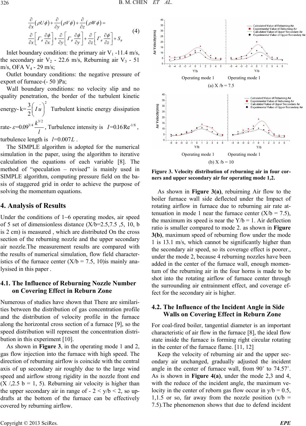 B. M. CHEN ET AL. 326 UVW xyz S xxyyzz (4) Inlet boundary condition: the primary air V1 -11.4 m/s, the secondary air V2 - 22.6 m/s, Reburning air V3 - 51 m/s, OFA V4 - 29 m/s; Outlet boundary conditions: the negative pressure of export of furnace-(- 50 )Pa; Wall boundary conditions: no velocity slip and no quality penetration, the border of the turbulent kinetic energy- 2 - 3 k= 2 I u Turbulent kinetic energy dissipation rate- 3/2 3/4 =0.09k l , Turbulence intensity is , -1/8 =0.16ReI turbulence length is . =0.007lL The SIMPLE algorithm is adopted for the numerical simulation in the paper, using the algorithm to iterative calculation the equations of each variable [8]. The method of “speculation – revised” is mainly used in SIMPLE algorithm, computing pressure field on the ba- sis of staggered grid in order to achieve the purpose of solving the momentum equations. 4. Analysis of Results Under the conditions of 1~6 operating modes, air speed of 5 set of dimensionless distance (X/b=2.5,7.5 ,5, 10, b is 2 cm) is measured , which are distributed On the cross section of the reburning nozzle and the upper secondary air nozzle.The measurement results are compared with the results of numerical simulation, flow field character- istics of the furnace center (X/b = 7.5, 10)is mainly ana- lysised in this paper . 4.1. The Influence of Reburning Nozzle Number on Covering Effect in Reburn Zone Numerous of studies have shown that There are similari- ties between the distribution of gas concentration profile and the distribution of velocity profile in the furnace along the horizontal cross section of a furnace [9], so the speed distribution will represent the concentration distri- bution in this experiment [10]. As shown in Figure 3, in the operating mode 1 and 2, gas flow injection into the furnace with high speed. The direction of reburning airflow is coincide with the central axis of up secondary air roughly due to the large wind speed and airflow strong rigidity in the nozzle front end (X /,2.5 b = 1, 5). Reburning air velocity is higher than the upper secondary air in range of - 2 < y/b < 2, so up- drafts at the bottom of the furnace can be effectively covered by reburning airflow. Operating mode 1 Operating mode 1 (a) X /b = 7.5 Operating mode 1 Operating mode 1 (b) X /b = 10 Figure 3. Velocity distri bution of reburning air in four cor- ners and upper secondary air for operating mode 1,2. As shown in Figure 3(a), rebuirning Air flow to the boiler furnace wall side deflected under the Impact of rotating airflow in furnace due to reburning air rate at- tenuation in mode 1 near the furnace center (X/b = 7.5), the maximum its speed is near the Y/b = 1. Air deflection ratio is smaller compared to mode 2. as shown in Figure 3(b), maximum speed of reburning flow under the mode 1 is 13.1 m/s, which cannot be significantly higher than the secondary air speed, so its coverage effect is poorer., under the mode 2, because 4 reburning nozzles have been added in the center of the furnace wall, enough momen- tum of the reburning air in the four horns is made to be shot into the rotating airflow of furnace center through the surrounding air entrainment effect, and coverage ef- fect for the secondary air is higher. 4.2. The Influence of the Incident Angle in Side Walls on Covering Effect in Reburn Zone For coal-fired boiler, tangential diameter is an important characteristic of air flow in the furnace [8], the ideal flow state inside the furnace is forming right circular rotating in the center of the furnace flame. [11, 12] Keep the velocity of reburning air and the upper sec- ondary air unchanged, gradually adjusted the incident angle in the center of furnace wall, from 90˚ to 74.57˚. As is shown in Figure 4(a), under the mode 2,3 and 4, with the reduce of the incident angle, the maximum ve- locity in the center of reborn gas flow occur in y/b = 0.5, 1,1.5 or so, far away from the nozzle position (x/b = 7.5).The phenomenon shows that due to defend incident Copyright © 2013 SciRes. EPE 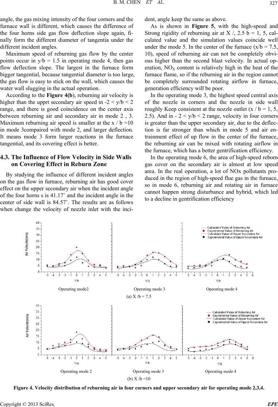 B. M. CHEN ET AL. Copyright © 2013 SciRes. EPE 327 angle, the gas mixing intensity of the four corners and the furnace wall is different, which causes the difference of the four horns side gas flow deflection slope again, fi- nally form the different diameter of tangentia under the different incident angles. Maximum speed of reburning gas flow by the center points occur in y/b = 1.5 in operating mode 4, then gas flow deflection slope. The largest in the furnace form bigger tangential, because tangential diameter is too large, the gas flow is easy to stick on the wall, which causes the water wall slugging in the actual operation. According to the Figure 4(b), reburning air velocity is higher than the upprt secondary air speed in -2 < y/b < 2 range, and there is good coincidence on the center axis between reburning air and secondary air in mode 2 , 3. Maximum reburning air speed is smaller at the x / b =10 in mode 3compaired with mode 2, and larger deflection. It means mode 3 form larger reactions in the furnace tangential, and its covering effect is better. 4.3. The Influence of Flow Velocity in Side Walls on Covering Effect in Reburn Zone By studying the influence of different incident angles on the gas flow in furnace, reburning air has good cover effect on the upper secondary air when the incident angle of the four horns s is 41.17˚ and the incident angle in the center of side wall is 84.57˚. The results are as follows when change the velocity of nozzle inlet with the inci- dent, angle keep the same as above. As is shown in Figure 5, with the high-speed and Strong rigidity of reburning air at X /, 2.5 b = 1, 5, cal- culated value and the simulation values coincide well under the mode 5. In the center of the furnace (x/b = 7.5, 10), speed of reburning air can not be completely obvi- ous higher than the second blast velocity. In actual op- eration, NOX content is relatively high in the heat of the furnace flame, so if the reburning air in the region cannot be completely surrounded rotating airflow in furnace, generation efficiency will be poor. In the operating mode 3, the highest speed central axis of the nozzle in corners and the nozzle in side wall roughly Keep consistent at the nozzle outlet (x / b = 1, 5, 2.5). And in - 2 < y/b < 2 range, velocity in four corners is greater than the upper secondary air, due to the deflec- tion is far stronger than which in mode 5 and air en- trainment effect of up flow in the center of the furnace, the reburning air can be mixed with rotating airflow in the furnace, which has a better gentrification efficiency. In the operating mode 6, the area of high-speed reborn gas cover on the secondary air is almost at low speed area. In the real operation, a lot of NOx pollutants pro- duced in the region of high-speed flue gas in the furnace, so in mode 6, reburning air and rotating air in furnace cannot happen strong disturbance and hybrid, which led to a decline in gentrification efficiency Operating mode2 Operating mode 3 Operating mode 4 (a) X /b = 7.5 Operating mode 2 Operating mode 3 Operating mode 4 (b) X /b =10 Figure 4. Velocity distribution of reburning air in four corners and upper secondary air for operating mode 2,3,4. 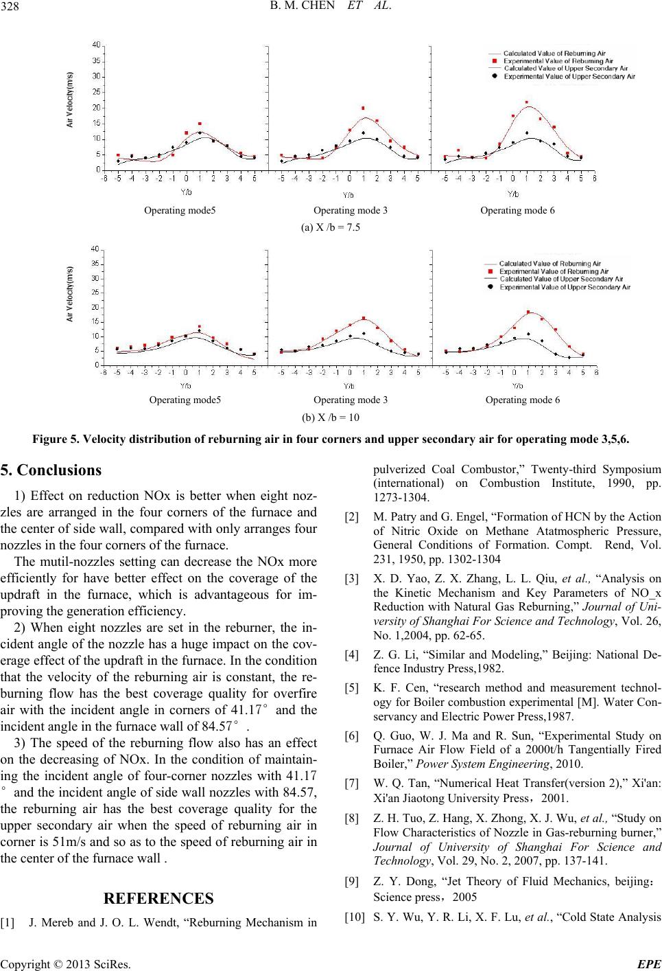 B. M. CHEN ET AL. 328 Operating mode5 Operating mode 3 Operating mode 6 (a) X /b = 7.5 Operating mode5 Operating mode 3 Operating mode 6 (b) X /b = 10 Figure 5. Velocity distribution of reburning air in four corners and upper secondary air for operating mode 3,5,6. 5. Conclusions 1) Effect on reduction NOx is better when eight noz- zles are arranged in the four corners of the furnace and the center of side wall, compared with only arranges four nozzles in the four corners of the furnace. The mutil-nozzles setting can decrease the NOx more efficiently for have better effect on the coverage of the updraft in the furnace, which is advantageous for im- proving the generation efficiency. 2) When eight nozzles are set in the reburner, the in- cident angle of the nozzle has a huge impact on the cov- erage effect of the updraft in the furnace. In the condition that the velocity of the reburning air is constant, the re- burning flow has the best coverage quality for overfire air with the incident angle in corners of 41.17°and the incident angle in the furnace wall of 84.57°. 3) The speed of the reburning flow also has an effect on the decreasing of NOx. In the condition of maintain- ing the incident angle of four-corner nozzles with 41.17 °and the incident angle of side wall nozzles with 84.57, the reburning air has the best coverage quality for the upper secondary air when the speed of reburning air in corner is 51m/s and so as to the speed of reburning air in the center of the furnace wall . REFERENCES [1] J. Mereb and J. O. L. Wendt, “Reburning Mechanism in pulverized Coal Combustor,” Twenty-third Symposium (international) on Combustion Institute, 1990, pp. 1273-1304. [2] M. Patry and G. Engel, “Formation of HCN by the Action of Nitric Oxide on Methane Atatmospheric Pressure, General Conditions of Formation. Compt. Rend, Vol. 231, 1950, pp. 1302-1304 [3] X. D. Yao, Z. X. Zhang, L. L. Qiu, et al., “Analysis on the Kinetic Mechanism and Key Parameters of NO_x Reduction with Natural Gas Reburning,” Journal of Uni- versity of Shanghai For Science and Technology, Vol. 26, No. 1,2004, pp. 62-65. [4] Z. G. Li, “Similar and Modeling,” Beijing: National De- fence Industry Press,1982. [5] K. F. Cen, “research method and measurement technol- ogy for Boiler combustion experimental [M]. Water Con- servancy and Electric Power Press,1987. [6] Q. Guo, W. J. Ma and R. Sun, “Experimental Study on Furnace Air Flow Field of a 2000t/h Tangentially Fired Boiler,” Power System Engineering, 2010. [7] W. Q. Tan, “Numerical Heat Transfer(version 2),” Xi'an: Xi'an Jiaotong University Press,2001. [8] Z. H. Tuo, Z. Hang, X. Zhong, X. J. Wu, et al., “Study on Flow Characteristics of Nozzle in Gas-reburning burner,” Journal of University of Shanghai For Science and Technology, Vol. 29, No. 2, 2007, pp. 137-141. [9] Z. Y. Dong, “Jet Theory of Fluid Mechanics, beijing: Science press,2005 [10] S. Y. Wu, Y. R. Li, X. F. Lu, et al., “Cold State Analysis Copyright © 2013 SciRes. EPE  B. M. CHEN ET AL. 329 on the Jet of Single Nozzle Using Gas-reburning for NOx Reduction,” Industrial Heating, Vol. 6, 2001, pp. 4-7. [11] Y. Wang, Y. K. Qin, S. H. Wu, et al., “Numerical Simu- lation and A nalysis of the Effect of an Infurnace Flow Field on the High Temperature Corrosion of Water Walls in a Tangentially Fired Boiler Fur n ace,” Journal of En- gineering for Thermal Energy and Power, Vol. 15, No. 87, 2000, pp. 284-329. [12] T. Zhu, W. D. Fan, et al., “A Numerical Simulation Study of Aerodynamic Field Characteristics in a Double Fur- nace,” Journal of Engineering for Thermal Energy and Power, Vol. 12, No. 06, 1997, pp. 401-477. Copyright © 2013 SciRes. EPE |