Y.-K. WU ET AL.
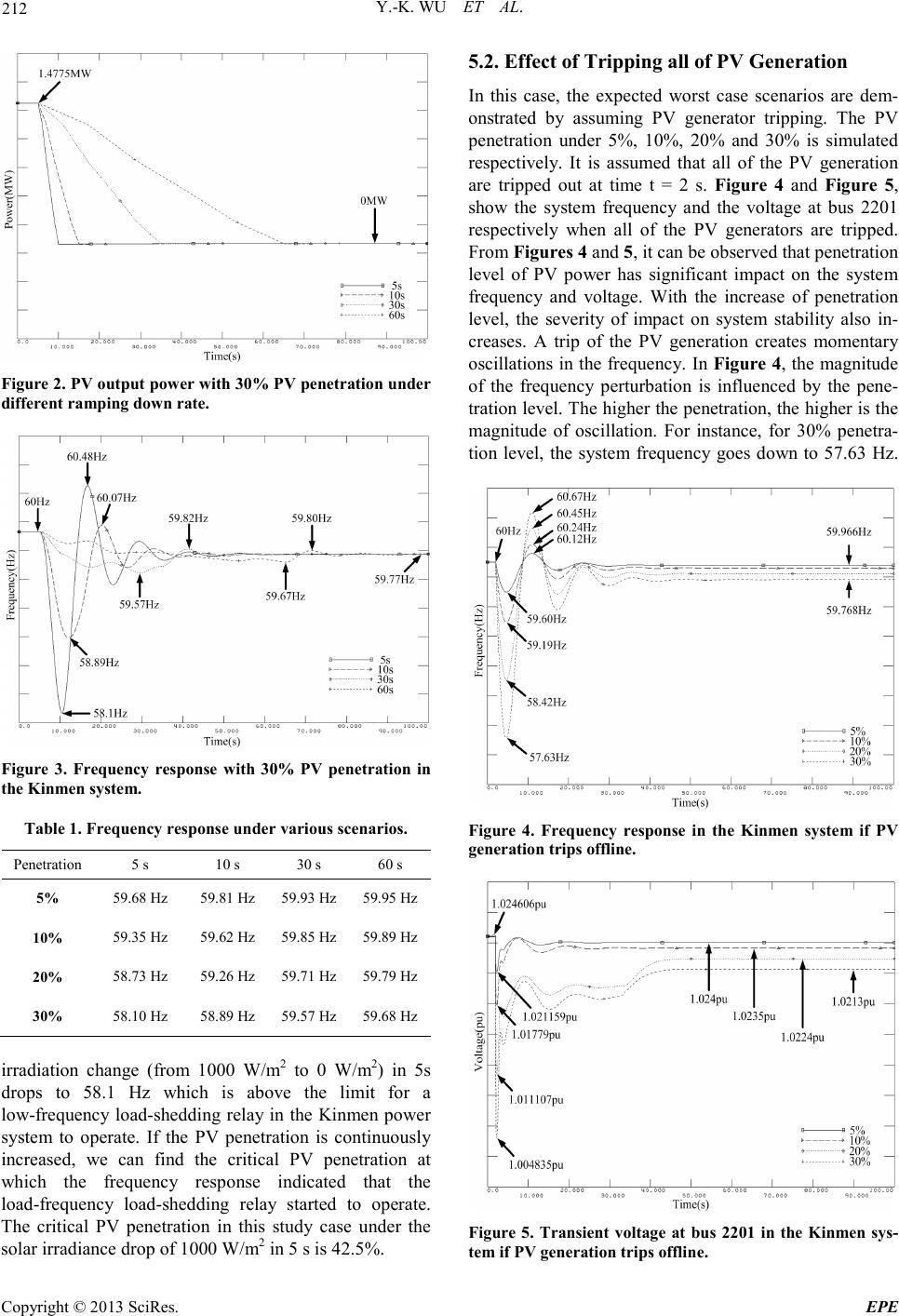
Copyright © 2013 SciRes. EPE
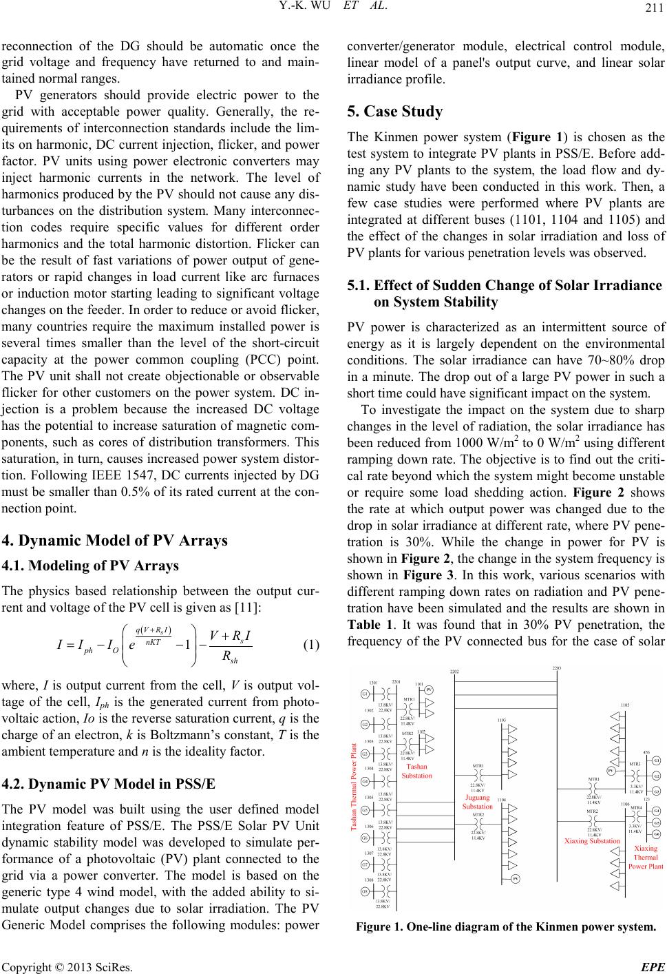
tric distribution system operations. As PV penetration
rises, new functionality from the inverter would need to
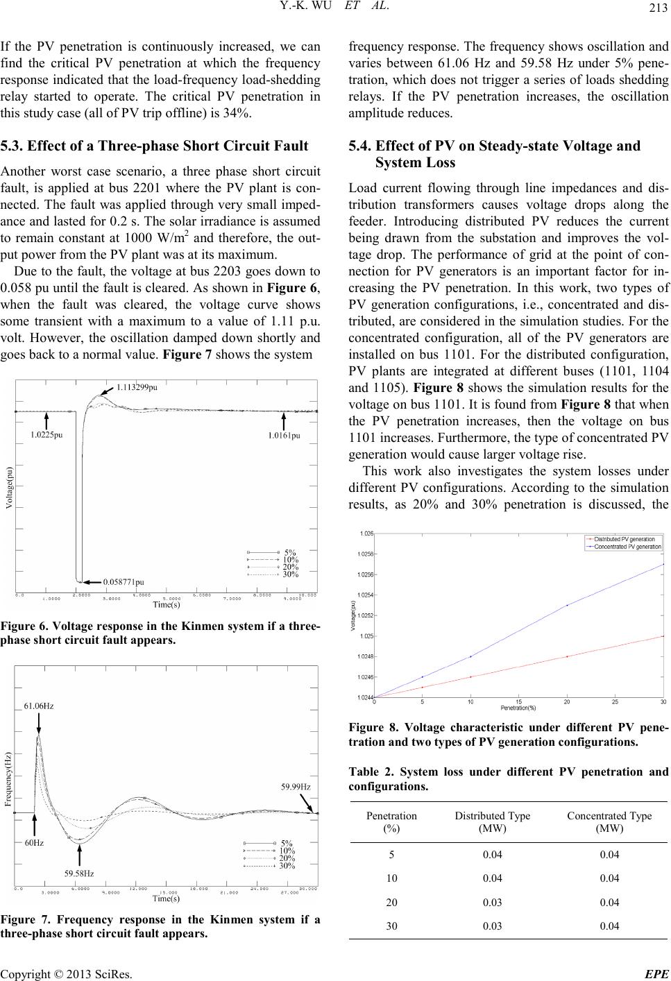
be incorporated. Advanced PV inverters should have the
following features: reactive power control, low voltage
ride through, dynamic control, and works like a tradi-
tional synchro nous generator .
Some of the projects demonstrated how the high pene-
tration of PV will affect operations of an electric distri-
butio n gr id . O the r i mpo r tant re sea r ch it e ms i n t he se DOE
projects include the evaluation of the effects of energy
storage in combination with distributed PV generation,
the benefits from high resolution data collection, the im-
pact of PV system integra tion on p ower syste m relia bility
indices, the impact of cloud movement on power quality,
the impact of feeder configuration and the PV location on
the maximum PV penetration.
This paper investigates several potential problems as-
sociated with high penetration levels of grid-tied PV.
Additionally, interconnection codes or standards for PV
generation and major requirements will be studied. Fi-
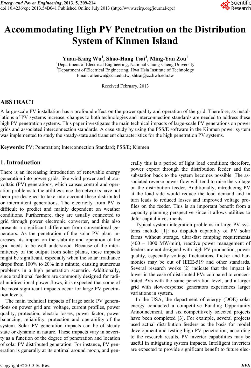
nally, a case study by using the PSS/E software in the
Kinmen power system was implemented to study the
steady-state and transient characteristics for the high pe-
netration PV systems.
2. Potential Problems Associated with High
Penetration Levels of Grid-tied PV
The International Energy Agency (IEA) has produced a
series of reports on Task V of the PV power systems
(PVPS). The demonstration projects issued by the IEA
have revealed that voltage rise is one of the primary
concerned problems [4]. The study in [5] also indicates
that PV penetration is limited to approximately 33% by
voltage rise issues in the UK. A study from Japan [6]
suggested that voltage rise is the most serious problem
and would limit penetration levels between 5% and 20%.
Any injection of power into a distribution system would
cause a voltage rise at the point of connection, and this
must be considered by network operators.
Voltage dips due to cloud transients might be an issue
at high PV penetration. Cloud cover and morning fog
require fast ramping and power balancing. Several re-
search works [7] examined cloud transient effects if the
PV were deployed as a central-station plant, and the re-
sults indicate that the maximum tolerable system level
penetration le vel of PV wo uld be limited by the tra nsient
following capabilities (ramp rates) of the conventional
generators. Additionall y, slo w volta ge reg ulatio n a nd fast
voltage regulation in high penetration PV scenarios
should also be addressed. To mitigate the effects of PV
output variability, energy storage systems are another
option, in which the PV inverter control system is inte-
grated into the system. The storage system will generate
or absorb energy as the PV power fluctuates according to
the available solar resource.
In terms of power quality, the results of several re-
search works reveal that the PV contribution to voltage
distortion is far les s than t he c ontributio ns made b y many
customer loads [8]. Therefore, harmonics would not be a
problem as long as the inverter has a well design.
3. Interconnection Codes and Standards
Grid connection guidelines are a major subject with re-
gard to PV gene rat ion. The connection rules and technic-
al requirements that differ from region to region make it
more complicated. IEC has been developing many stan-
dards re lated to individual DG te chnologie s includi ng P V
generators. These guidelines would serve as input to de-
velop a more general connecting guideline for all types
of distributed generation systems and their interactions
with the grid. In 2000, the IEEE published IEEE Stan-
dard 929 IEEE Recommended Practice for Utility Inter-
face of Photovoltaic (PV) Systems up to 10 kW [9]. Thi s
standard was updated from IEEE Standard 929-1988 by
incorporating developments in the PV industry and by
coordinating with UL1741 1999; meanwhile, the IEEE
Standards Coordinating Committee 21 on Fuels, Photo-
voltaics, Dispersed Generation, and Energy Storage
formed a working group to develop the IEEE Standard
for Interconnecting Distributed Resources with Electric
Power Systems, or IEEE Standard 1547 [10]. It provides
a uniform standard for interconnection of distributed re-
sources with electric power systems, and also provides
requirements relevant to performance, operation, testing,
safety and maintenance of the interconnection. In Europe,
every country has its own technical requirements. How-
ever, major requirements in these interconnection codes
for distributed generators or PV generation include gen-
eral requirements and specifications, safety and protec-
tion requirements, and power quality requirements.
For general requirements and specifications, most
standards use a power size to limit the scope. IEEE 929
uses 10 kW and limits the technology to PV systems,
while IEEE 1547 uses 10 MVA and attempts to cover all
technologies. In addition, different PV interconnection
standards specify different requirements on voltage vari-
ation, system frequency, synchronization, and voltage
unbalance. As fo r safety and protection requirements, PV
generators must detect and respond to abnormal condi-
tions occurring on the power distribution systems. For
instance, in almost all technical requirements and stan-
dards, unexpected islanding operation is not wanted. PV
units must be disconnected as soon as possible when the
mai n grid is not energized. All interconnected PV plants
must have a readily accessible, lockable, visible-break
isolation switch s hall be located between the DG unit and
the gri d. T hi s d isconnectio n switc h must ac cessible to the
distribution co mpany. In addition, after grid fault, the