D. JOHNSTON 199
PV inverter, resulting in better regulation.
Many of the larger loads are heating and/or air condi-
tioning systems. Due to the large heat capacity of the
building components – walls, floors, etc – and water
tanks, these loads can be operated for limited periods, if
necessary, independently of their normal thermostatic
controls, without adverse changes in temperature. This
feature allows such systems to be used as switchable
loads, for regulation of voltage and/or frequency during
islanding operation [4]. Other loads, such as room light-
ing and electronic appliances are controlled according to
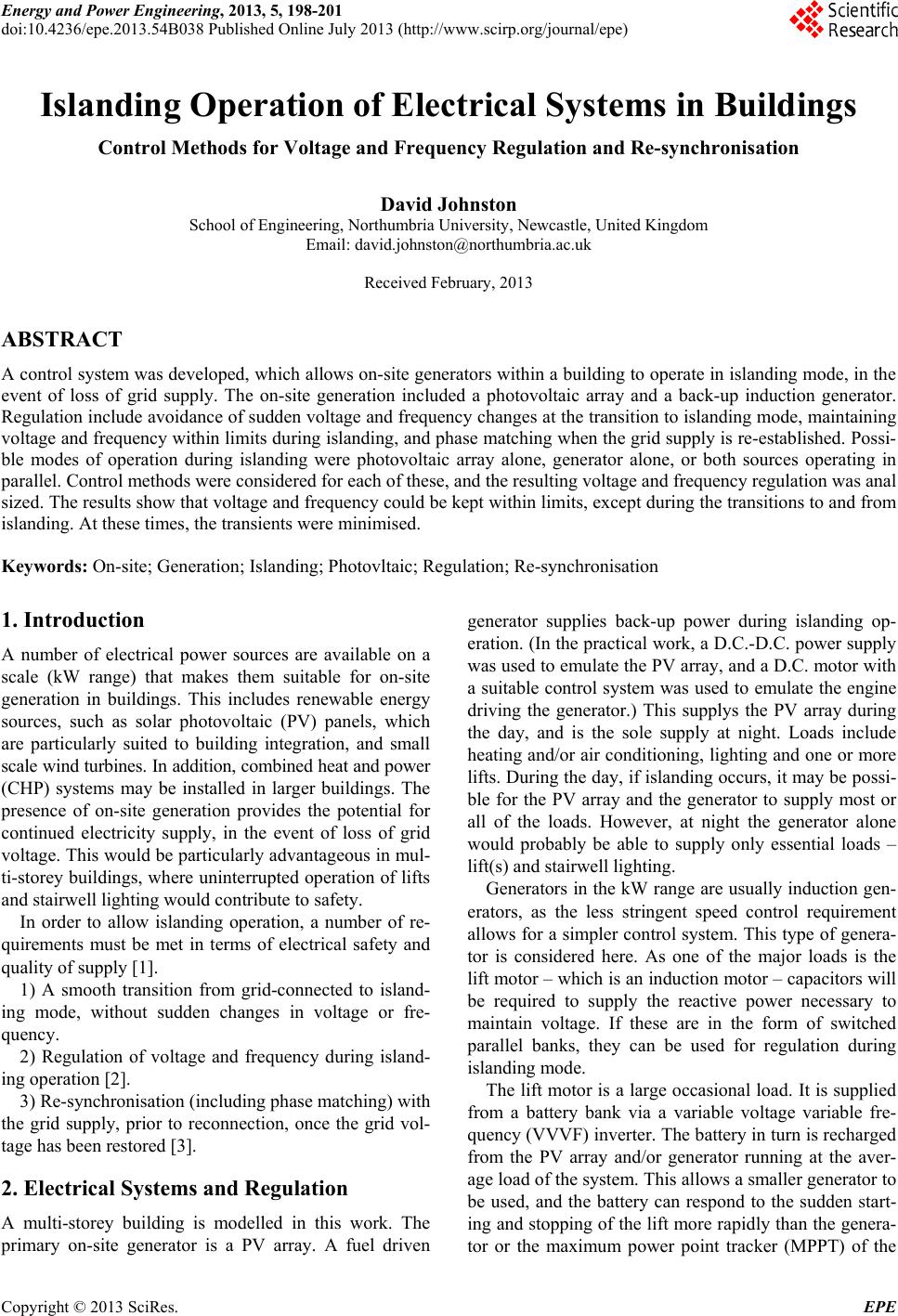
user preferences. A simplified schematic circuit of the
power sources and loads is shown in Figure 1.
Depending on the available solar energy and the load-
ing conditions, three modes of operation are possible
during islanding.
The output of the PV array is sufficient to supply
the essential services, the user-controlled loads and
some of the switchable loads. These switchable
loads are then used as the primary means of voltage
regulation.
The output of the PV array is not sufficient to sup-
ply the essential services and the user-controlled
loads. The generator is then used to make up the
deficit. The associated capacitors provide an addi-
tional mechanism for regulation of voltage and/or
frequency.
The generator is the only electrical power source
(islanding at night). The loads are reduced to the
essential services and possibly some of the higher
priority user-controlled loads. The capacitors again
provide an additional mechanism for regulation, in
this case in conjunction with the mechanical power
supplied to the generator.
The switchable loads can also be used to limit rapid
voltage and frequency deviations during the transition to
islanding mode. (As the generator is for back-up, it does
not switch on until shortly after this time, so reactive
power compensation – and hence capacitors – are not
present at the transition.)
During re-synchronisation, all currently operating ge-
nerators must be brought into phase with the grid voltage,
maintaining synchronisation with each other as
Photovoltaic
Array
Generator
Lift
Swit cha ble
Loads
User
Controlled
Loads
Grid
Connector
Grid
Suppl y
Figure 1. Simplified schematic circuit of on-site generation
and loads, together with grid connection, for a typical multi-
storey building.
they do so. Common practice for PV inverters is to use a
phase-locked loop (PLL) to synchronise its output with
the grid, after which the grid connection is closed. For
induction generators,the grid connection is re-established
first (generally via a soft start unit) and the generator
then automatically re-synchronises. In a system where
either or both of these generators may be operating, it is
easier to implement a universal control method if both
types re-synchronise in the same order. The capacitor
banks connected to the generator allow the frequency to
be controlled. A phase detector, using the grid voltage as
its reference, can be used with the generator/capacitors to
form a PLL. This can re-synchronise with the grid, after
which the grid connection is close – in the same order as
for the PV inverter.
3. Results – Regulation of Voltage and
Frequency
The results for voltage regulation for a PV array only are
shown in Figure 2. For a relatively large building, with a
high power array and a large number of switchable loads,
switching of a single load results in a small change in
voltage. Thus, the voltage can be kept within limits.
However, for a smaller building, with a lower powered
array and fewer switchable loads, switching a single load
results in a larger change in voltage. This may overshoot
or undershoot the voltage limits, in an unstable oscilla-
tion. The problem was corrected by implementing the
rectifier – connecting the battery to the building’s A.C.
cabling – as an inverter with bi-directional power flow,
allowing the battery to act as a load or source of electri-
cal power with a continuously variable input/output. The
resulting voltage is approximately constant and remains
within the limits.
200
210
220
230
240
250
260
0 102030405
Time (s)
Voltage (V)
0
Large bui ldi ng, many loadsSmall building, few loads
F ew loads + battery
Figure 2. Voltage regulation by switchable loads with PV
array as electrical source. Initial rise in voltage is due to
controlled increase in PV output power.
Copyright © 2013 SciRes. EPE