Paper Menu >>
Journal Menu >>
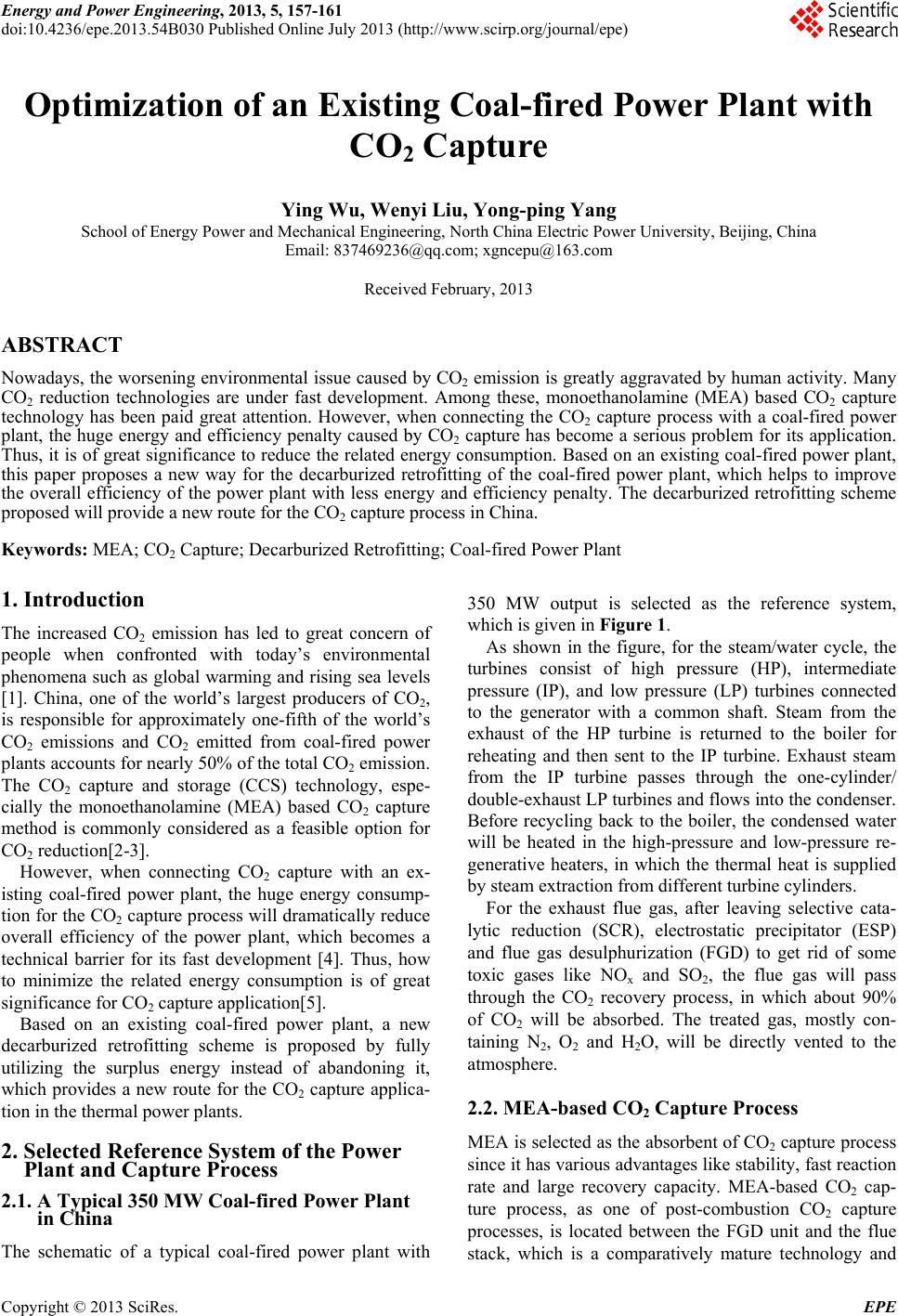 Energy and Power Engineering, 2013, 5, 157-161 doi:10.4236/epe.2013.54B030 Published Online July 2013 (http://www.scirp.org/journal/epe) Optimization of an Existing Coal-fired Power Plant with CO2 Capture Ying Wu, Wenyi Liu, Yong-ping Yang School of Energy Power and Mechanical Engineering, North China Electric Power University, Beijing, China Email: 837469236@qq.com; xgncepu@163.com Received February, 2013 ABSTRACT Nowadays, the worsening environmental issue caused by CO2 emission is greatly aggravated by human activity. Many CO2 reduction technologies are under fast development. Among these, monoethanolamine (MEA) based CO2 capture technology has been paid great attention. However, when connecting the CO2 capture process with a coal-fired power plant, the huge energy and efficiency penalty caused by CO2 capture has become a serious problem for its application. Thus, it is of great significance to reduce the related energy consumption. Based on an existing coal-fired power plant, this paper proposes a new way for the decarburized retrofitting of the coal-fired power plant, which helps to improve the overall efficiency of the power plant with less energy and efficiency penalty. The decarburized retrofitting scheme proposed will provide a new route for the CO2 capture process in China. Keywords: MEA; CO2 Capture; Decarburized Retrofitting; Coal-fired Power Plant 1. Introduction The increased CO2 emission has led to great concern of people when confronted with today’s environmental phenomena such as global warming and rising sea levels [1]. China, one of the world’s largest producers of CO2, is responsible for approximately one-fifth of the world’s CO2 emissions and CO2 emitted from coal-fired power plants accounts for nearly 50% of the to tal CO2 emission. The CO2 capture and storage (CCS) technology, espe- cially the monoethanolamine (MEA) based CO2 capture method is commonly considered as a feasible option for CO2 reduction[2-3]. However, when connecting CO2 capture with an ex- isting coal-fired power plant, the huge energy consump- tion for the CO2 capture process will dramatically reduce overall efficiency of the power plant, which becomes a technical barrier for its fast development [4]. Thus, how to minimize the related energy consumption is of great significance for CO2 capt ure application[5]. Based on an existing coal-fired power plant, a new decarburized retrofitting scheme is proposed by fully utilizing the surplus energy instead of abandoning it, which provides a new route for the CO2 capture applica- tion in the thermal power plants. 2. Selected Reference System of the Power Plant and Capture Process 2.1. A Typical 350 MW Coal-fired Power Plant in China The schematic of a typical coal-fired power plant with 350 MW output is selected as the reference system, which is given in Figure 1. As shown in the figure, for the steam/water cycle, the turbines consist of high pressure (HP), intermediate pressure (IP), and low pressure (LP) turbines connected to the generator with a common shaft. Steam from the exhaust of the HP turbine is returned to the boiler for reheating and then sent to the IP turbine. Exhaust steam from the IP turbine passes through the one-cylinder/ double-exhaust LP turb ines and flows into the conden ser. Before recycling back to the boiler, the condensed water will be heated in the high-pressure and low-pressure re- generative heaters, in which the thermal heat is supplied by steam extraction from different turbine cylinders. For the exhaust flue gas, after leaving selective cata- lytic reduction (SCR), electrostatic precipitator (ESP) and flue gas desulphurization (FGD) to get rid of some toxic gases like NOx and SO2, the flue gas will pass through the CO2 recovery process, in which about 90% of CO2 will be absorbed. The treated gas, mostly con- taining N2, O2 and H2O, will be directly vented to the atmosphere. 2.2. MEA-based CO2 Capture Process MEA is selected as the absorbent of CO2 capture process since it has various advantages like stability, fast reaction rate and large recovery capacity. MEA-based CO2 cap- ture process, as one of post-combustion CO2 capture processes, is located between the FGD unit and the flue stack, which is a comparatively mature technology and Copyright © 2013 SciRes. EPE  Y. WU ET AL. 158 has a bright future to be utilized on a large scale. The MEA-based CO2 capture process is shown in Figure 2. From Figure 2, the MEA-based CO2 capture process can be summarized as follows: (1) The flue gas is com- pressed by a booster fan; (2) The CO2 in the flue gas is absorbed by MEA in an absorber and the treated flue gas will be directly vented to the atmosphere; (3) The rich amine solution with CO2 is delivered to a heat exchanger by a pump; (4) The rich amine solution will release CO2 and lean ammonia solution in the stripper by reboiler operation; (5) The high-purity CO2 will be flashed in a CO2 cooler, and later compressed and cooled for trans- port and storage; (6) Contrary to the rich amine solution, the lean ammonia solution leaving from the stripper will release energy in the heat exchanger and be recycled back to the absorber. (7) The makeup MEA solution is also added into the absorber. The main parameter of the MEA-based CO2 capture process is shown in Table 1. Figure 1. A typical 1000 MW coal-fired power plant in China. Figure 2. MEA-based CO2 capture process. Copyright © 2013 SciRes. EPE 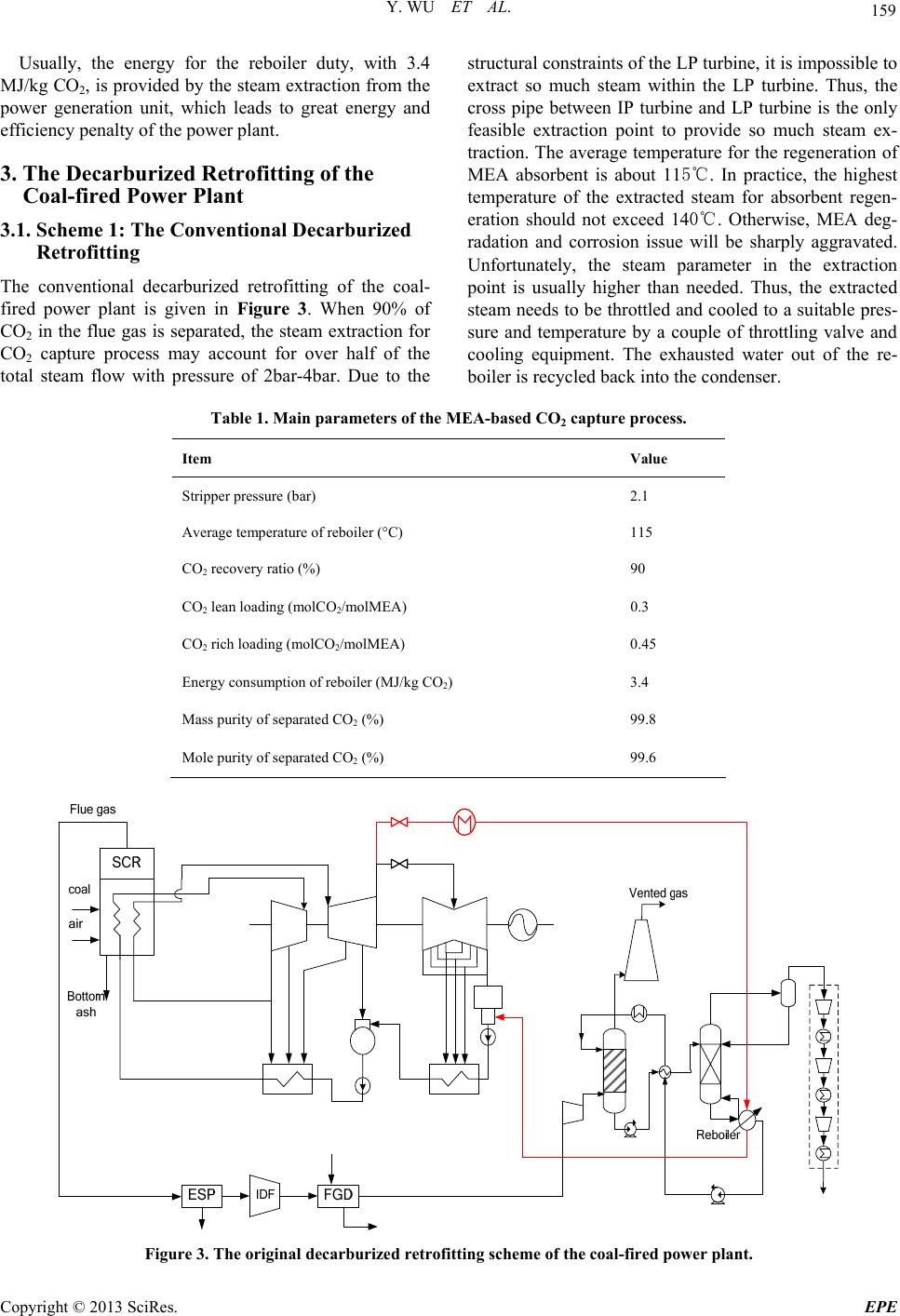 Y. WU ET AL. 159 Usually, the energy for the reboiler duty, with 3.4 MJ/kg CO2, is provided by the steam extraction from the power generation unit, which leads to great energy and efficiency penalty of the power plant. 3. The Decarburized Retrofitting of the Coal-fired Power Plant 3.1. Scheme 1: The Conventional Decarburized Retrofitting The conventional decarburized retrofitting of the coal- fired power plant is given in Figure 3. When 90% of CO2 in the flue gas is separated, the steam extraction for CO2 capture process may account for over half of the total steam flow with pressure of 2bar-4bar. Due to the structural constraints of the LP turbine, it is impossible to extract so much steam within the LP turbine. Thus, the cross pipe between IP turbine and LP turbine is the only feasible extraction point to provide so much steam ex- traction. The average temperature for the regeneration of MEA absorbent is about 115℃. In practice, the highest temperature of the extracted steam for absorbent regen- eration should not exceed 140℃. Otherwise, MEA deg- radation and corrosion issue will be sharply aggravated. Unfortunately, the steam parameter in the extraction point is usually higher than needed. Thus, the extracted steam needs to be throttled and cooled to a suitable pres- sure and temperature by a couple of throttling valve and cooling equipment. The exhausted water out of the re- boiler is recycled back into the condenser. Table 1. Main parameters of the MEA-based CO2 capture process. Item Value Stripper pressure (bar) 2.1 Average temperature of reboiler (°C) 115 CO2 recovery ratio (% ) 90 CO2 lean loading (molCO2/molMEA) 0.3 CO2 rich loading (molCO2/molMEA) 0.45 Energy consumption of reboiler (MJ/kg CO 2) 3.4 Mass purity of sep a rated CO2 (%) 99.8 Mole purity of separated CO2 (%) 99.6 Figure 3. The original decarburized retrofitting scheme of the coal-fired power plant. Copyright © 2013 SciRes. EPE  Y. WU ET AL. 160 3.2. Scheme 2: Optimization of the Decarburized Retrofitting The decarburized system in Section 3.1 realizes the CO2 capture in cost of great energy consumptio n. Suppose the surplus energy in the extracted steam can be utilized, it will be certain to improve the thermal performan ce of th e decarburized system. Thus, to recover the surplus pressure of the extracted steam, a new letdown steam turbine generator (LSTG) is installed to recover the surplus energy of the extracted steam in the new decarburized system, as shown in Fig- ure 4. Such improvement is really simple and easy to implement while it is very effective to retrieve the sur- plus pressure and temperature, which can also make the output p ower gre a t ly increase t o a certain de g r e e. 3.3. Performance Evaluation of the Two Capture Systems Performance evaluation of the two capture systems is conducted in Table 2. It is easy to find that, with the help of new LSTG, the net power generation is increased from 211.25 MW to 230.36 MW. The efficiency of the new decarburized sys- tem has increased to 28.01% with 12.03% efficiency penalty compared to 14.35% of the original decarburized system. Thus, the energy-saving effects in the steam ex- traction point are obvious. 4. Techno-economic Analysis of the Two Capture Systems Techno-economic analysis of the original power plant and two retrofitting schemes is conducted in Table 3. As shown in the table, the total plant investment of reference system (230.52 M$) are estimated according to the related data of typical 350 MW coal-fired power plants in China with specific plant investment of ap- proximately 700 $/kW. The total investment of CO2 cap- ture process, estimated based on some demonstration plant in China, reaches 92.15 M$. Due to the connection with the CO2 capture process, the total plant investment of scheme 1 has reached up to 322.67 M$ with specific plant investment of 1527.43 $/kW. For scheme 2, al- though the total plant investment is further increased to 324.27 M$ with consideration of the added LSTG and the related retrofitting cost, its specific plant investment is reduced to 1407.67 $/kW because of the increased net power generation. Figure 4. The new decarburized retrofitting scheme of the coal-fired power plant. Table 2. Overall performance of two capture system. Item Original New HP, IP & LP power output (MW) 260.37 260.37 LSTG power output ( % ) - 19.11 Gross power output (MW) 260.37 279.48 Internal power consumption (MW) 17.33 17.33 Power for CO2 capture process (MW) 31.79 31.79 Net power generation (MW) 211.25 230.36 Total energy of coal input (LHV) 822.39 822.39 Net plant efficiency (%) 25.69% 28.01% Original plant effic iency (%) 40.04% 40.04% Efficiency penalty (%) 14.35% 12.03% Copyright © 2013 SciRes. EPE  Y. WU ET AL. 161 Table 3. Techno-economic analysis results. Item Reference Scheme 1 Scheme 2 Net plant efficiency (%) 40.04% 25.69% 28.01% Net power generation (MW) 329.32 211.25 230.36 Total plant investment (M$) 230.52 322.67 324.27 Specific plant investment ($/kW) 700.00 1527.43 1407.67 Cost of electricity (COE, $/MWh) 57.75 103.49 94.70 CO2 emission rate (tCO2/MWh) 0.87 0.14 0.12 CO2 avoided rate (tCO2/MWh) 0 0.73 0.75 Cost of CO2 avoided ($/t CO2) 0 62.66 49.27 For cost of electricity (COE) and cost of CO2 avoided, both of two parameters have the same trend. Their values in scheme 1 are increased when compared to the refer- ence system. However, for scheme 2, due to the in- creased net power generation, their values are reduced compared to scheme 1. To sum up, with the added LSTG, the net efficiency and net electricity generation of the new retrofitting scheme increases while its specific plant investment, COE and th e cost of CO2 avoided reduces, which reflects the economic advantage of the new retrofitting scheme. 5. Conclusions This paper carries out the decarburized retrofitting study of an existing coal-fired power plant in China. Since the energy consumption of the CO2 capture process is ex- tremely huge, the energy and efficiency penalty caused by CO2 capture process becomes a technical barrier for the large-scale CO2 capture application. Optimization measures are conducted in the conven- tional decarburized retrofitting scheme. Based on the conventional scheme, a new LSTG is added to recover the surplus energy existed in the extracted steam. Per- formance results also show its benefits. The added LSTG helps the improvements of the overall performance of the power plant and provides a new route for the CO2 cap- ture application in coal-fired power plants. Finally, techno-economic results are also conducted. From the results, it is easy to find that the net efficiency and net electricity generation of the new retrofitting scheme increases while its specific plant investment, COE and th e cost of CO2 avoided reduces, which reflects economic benefits of the new retrofitting scheme. 6. Acknowledgements This study has been supported by the National Key Technology R&D Program of China (2012BAC24B01), National Nature Science Foundation Project (51006034, 51061130538), the Fundamental Research Funds for the Central Universities (11 MG04) and Internation al Science and Technology Cooperation Project (2010DFA 72760- 609). REFERENCES [1] Working Group III of the Intergovernmental Panel on Climate Change (IPCC), “IPCC Special Report on Car- bon Dioxide Capture and Storage,” Cambridge, United Kingdom: Cambridge University Press, U.K., 2005. [2] China Electricity Council, “The Current Status of Air Pollution Control for Coal-fired Power Plants in China 2009,” China Electric Power Press, Beijing, 2009. [3] Intergovernmental Panel on Climate Change (IPCC) Cli- mate Change 2001: Mitigation, Cambridge: Cambridge University Press, U.K., 2001. [4] Energy Information Administration, “International En- ergy Outlook 2009,” DOE/EIA-0484, 2009. [5] Updated Capital Cost Estimates for Electricity Generation Plants 2010, U.S. Energy Information Administration. Copyright © 2013 SciRes. EPE |