Energy and Power Engineering, 2013, 5, 92-96
doi:10.4236/epe.2013.54B018 Published Online July 2013 (http://www.scirp.org/journal/epe)
Analysis of Re Influence on MILD Combustion of Gas
Turbine
Lijun Wang1, Dongdong Qi2, Xiaowei Sui2, Xin Xie1
1Shenyang Aerospace University, Shenyang, College of Energy and Environment
2Shenyang Aerospace University, Division of Aerospace Engineering, Shenyang
Received January, 2013
ABSTRACT
The paper numerical studied the MILD(Moderate or Intense Low-oxygen Dilution) combustion mode and performances
in the designed gas turbine chamber. The influence of air jet Re number on flue gas recycles ratio Kv and hereby on
kerosene fuel MILD combustion were modeled. For fixed equivalence ratio, increasing the air jet Re number to the Kv
value of 3.3 - 3.8, MILD combustion mode will be formed. It has MILD combustion performances of volume combus-
tion, excellent outlet temperature field and very low pollutant emissions. Combustor confinement has little effects on
MILD combustion. Calculating results agree with other’s similar experimental data.
Keywords: Gas Turbine; MILD Combustion; Combustion Performance; Numerical Study
1. Introduction
In the last decades of the 20th century, there are many
researches focus on the high efficiency and low emission
combustion. New types of combustion mode and theory
such as LPP(Lean Premix Pre-vaporized Combustion)
and RQL(Rich Burn-Quench-Lean Burn) had put for-
ward. However, these combustion molds can hardly sat-
isfy the requirements of high efficiency and low emis-
sions simultaneously unless combined with the staged
combustion or variable geometry combustor, and has not
been applied to gas turbine successfully[1]. The current
MILD (Moderate Intense Low Oxygen Dilution)
mode have more advantageous performances of high
combustion efficiency and super low emissions[2].
MILD combustion is a burning mode under the
condition of low oxygen diluted, which is also known as
Flameless Combustion, Colourless Combustion or FLOX
(Flameless Oxidation). MILD combustion mode has the
characteristics of volume or dispersion combustion
which eliminates the flame frontal surface under normal
temperature air. Gas, liquid, solid and other low caloric
fuel can be extensively used to reduce pollutants
emission and combustion noise[2]. From 1991 when
Wunning[3] applied flameless combustion to industrial
furnace by high speed jet entrain flue gas on, it is
necessary to preheat the air above 1000K for MILD
combustion mode at the beginning. For the current period,
all kinds of fuel can be used for MILD combustion based
on the air jet of normal temperature[4-6]. The application
scope of MILD combustion is expanded from various
industrial furnaces to high-tech field includes gas turbine
and aeroengine[7-11]. Great differences of operating
condition between industrial furnace and gas turbine lead
to grand technical challenge [10]. Nowadays, this research
is on a stage of rapid development including mechanism
analysis, experiment and numerical simulation.
2. Model and Computational Grid
Figure 1 shows the 1/12 symmetrical body of the
chamber and the local computational mesh of cross-
section near the head of chamber. Tubular combutor
model combustor is adopped and the working pressure in
chamber is 0.4 MPa with the combustion intensity of 25
MW/(m3·atm). The model chamber is composed of head
section and flame tube. The air into the flame tube
injected cooling air in the casing, which improve the air
flow distribution. 12 air-atomizer noozles and 12 dilution
holes are installed circumferential distributed evenly. The
(a) Local grid dissection (b) 1/12 symmetric body
sh.
*Sponsored by The Aero Science Foundation of China (NO. 20112B
54005) Figure 1. 1/12 Model chamber and local section me
Copyright © 2013 SciRes. EPE
L. J. WANG ET AL. 93
chet
model chamber is divided by structured and un-
st
ns
continuous phase of
amber dimension is 100 mm × 420 mm with two outl
styles of shrinkage tube and direct tube(labeled by dotted
line).
The
ructured mixing meshes for its complicated structures.
Grid numbers of direct tube and shrinking outlet are
884,869-857,855 respectively.
3. Mathematical Models
3.1. The Governing Equatio
The basic governing equations for
turbulent combustion reaction flow are expressed as
() (),
uS
i
xxx
jjj
S
p

 
 (1)
in which

i
u is the time average value of velocity
(2)
component,
Φ
is the universal variant of turbulent
velocity component, turbulent kinetic energy k and its
dissipation rate ε, total enthalpy h and mass fraction mi
(i = C12H23O2CO2H2ON2COH2NO).
is
effective diffusion coefficient,
is the source term
of the gas continuous phase,
p,
is the interaction
source term between the particles phase of kerosene and
continuous phase, ρ stands for density of gas phase,
which depends on the gas state equation. The governing
equations are closed by Realizable k-ε turbulence
model and standard wall function is adopted near the
wall. C12H23 represents aviation kerosene. A joint model
with multistage finite-rate chemical reaction and EDC
model is adopted to simulate the interaction between the
turbulence and chemical reaction, revealed in formula(2).
The reaction rate is controlled by the minor rate of EDC
conceptual model (3) and finite-rate chemical reaction
model rate (4)

min ,
ieddy Chem
RRR
4.0 min,
ox
eddy fu
fu
m
Rm
kr


(3)
 

exp
ab
E
R
T
Chem
RA fueloxygen
(4)
r is chemical equivalence ratio. A, E and T stand for
3.2. Calculation Conditions
mpressor of gas turbine
4. Results and Discussion
Combustion
than 1.13×
10
Table 1. Calculation conditions.
Rein Fuel g
fu
pre-exponential factor, activation energy and gas
temperature respectively. Thermal NO and fast NO
model are both used for NOx generation. P1 Radiation
model and radiative properties calculation of flue gas are
used. Discrete phase of oil fuel particles are calculated by
discrete random wander model, and the Lagrange equation
describing fuel particles speed, mass and rate of temperature
change is solved. The source term
p,
in equation (1) is
calculated by PSI-CELL model. The size of atomized
particles conforms Rosin-Rammler distribu- tion, and the
effect of gas turbulent fluctuation on particles speed is
considered. Temperature polynomial function is used for
describing physicochemical properties of gas component
and fuel. Thermal-gas-solid coupled boundary condition is
advisable. CFD calculation is carried on the commercial
software FLUENT6.3 designed by ANSYS[12].
Air inlet temperature from the co
is assumed 800 K and equivalence ratio Φ is 0.62. Effect
of outlet on MILD combustion defined by geometric
factor g = doutlet/dtube is 0.44 and 1 for shrinkage and
direct outlets respectively. The calculation conditions are
listed in Table 1.
4.1. Effect of Rein on MILD
1) MILD Combustion Temperature Field
Figure 2 shows that, when Rein is larger
5, MILD combustion mode has formed volume flame
of flame front surface disappears, local temperature
difference is less than 50 K after flame lift off zone, Taver
is about 1540 ~ 1541 K.
mass flow(kg/s) Φ
1. 5 1/4 13×10 0.001 44 0.620.4
1.50×10⁵ 0.001 92 0.62 1/0.44
1.88×10⁵ 0.002 40 0.62 1/0.44
Tmax= 2311 K,Taver = 1530 K,Twall = 977 K,Tout = 1035 K
(a) Rein = 1.13×10⁵
Tmax = 2326 K, Taver = 1533 K, Twall = 994 K, Tout = 1046 K
(b) Rein=1.50×10⁵
Tmax = 2351 K,Taver = 1541 K,Twall = 1016 K,Tout = 1053 K
(c) Rein = 1.88×10⁵
Figure 2. Effect of Rein on temperature fie. ld
Copyright © 2013 SciRes. EPE
L. J. WANG ET AL.
94
2) Fl
of experiment and
ca
ue Gas Recirculation Rate Kv
Previous MILD combustion results
lculation indicated flue gas recirculation rate Kv was
important for MILD combustion mode[2]. The larger the
combustion air jet momentum is, the greater of flue gas
recirculation rate Kv, and the lower oxygen concentra-
tion[11]. High velocity air jet which induced stiring
action of momentum, that accelerated by combustion
heat release and viscous shearing force is main influence
factor of Kv. Numerical simulation is an effective means
of researching on this complicated action. Local Kv(x)
value is defined as
()
()
()
()
rec
vair injectionfuel
rec rec
Ax
air injectionfuel
Mx
Kx MM M
vdAx
MM M


 (5)
Mrec is the mass flow of flue gas, kg/s. Mair and Mfuel are
urning,
K
mass flow rate of air jet and kerosene, kg/s. Minjection is
the secondary mass flow rate of injected air from the
casing. A(x) is local across section area of flame tube, m2.
ρrec, vrec is local density and velocity separately.
For ordinary combustion mode like bluff body b
v is kept 0.3 - 0.5, but Kv for MILD combustion is
larger than 3[2]. The calculating results of Kv in the gas
turbine this MILD chamber for kerosene fuel is showed
in Figure 4, which can be verified by Craya-Curtet
experimental formula[13].
0
( )0.321
flue
vin in
xx
Kx D

(6)
D is the inner diameter of the injector, m. ρflue is
flu
e MILD combustion
m
performance of pollutant of NOx
em
i.e. Kv is larger than 3.3,
th
efficient can be
de
in
e gas density in the reference temperature, kg/m3. ρ
in is the reactant density of inlet temperature, kg/m3. x0 is
the original injecting coordinate, m.
Levy Y. etc. had researched on th
ode in the gas turbine chamber and indicate that MILD
combustion mode may be built as Kv is larger than
3.0[10]. Figure 3 showed that when Rein 1.13 × 10⁵,
at the flame lift-off location x = 0.132m, its local Kv is
1.365, 1.191 and 1.182 respectively, are both larger than
0.3~0.5 of ordinary stable combustion mode such as bluff
body combustion. The backflow entrainment of high
temperature flue gas has effects of heating and ignition
on lift off zone of combustible mixture and may induce
MILD combustion mode. Furthermore, Kv at recircula-
tion zone center is between 3.3 and 3.8 in the Figure 3,
which represents the formed MILD mode and corresponds
to the existing experiment results of fuels. The entrain-
ment air from casing has a stabilized effect on the Kv,
which is beneficial to MILD state. Kv calculation results
fit the Craya-Curtet formula in Figure 3.
3) NOx Emossion
MILD combustion
isssion show in Figure 4.
When Rein 1.13 × 10⁵
e average combustion temperature is about 1530~ 1541
K and NOx emission is between 15 and 16.5ppm
analogous to 18ppm of experiment result[14].
4) Outlet temperature field quality
The temperature distribution co
scribed as OTDFmax, which is showed as
4max4
max
43
OTDF t
t
TT
TT
(7)
T4max is outlet temperature peak value, T4 is the outlet
circumferential average temperature, T3 is the entrance
average temperature. OTDFmax calculation results are
between 0.293 and 0.267, decrease with Rein increasing,
but far less than 0.35 of ordinary combustor. The lager
Rein, the smaller OTDFmax. Temperature field quality
of outlet section is clearly uniform.
Figure 3. Kv(x) calculating vs. experimental.
Figure 4. NOx Emission(ppm@15%O2).
Copyright © 2013 SciRes. EPE
L. J. WANG ET AL. 95
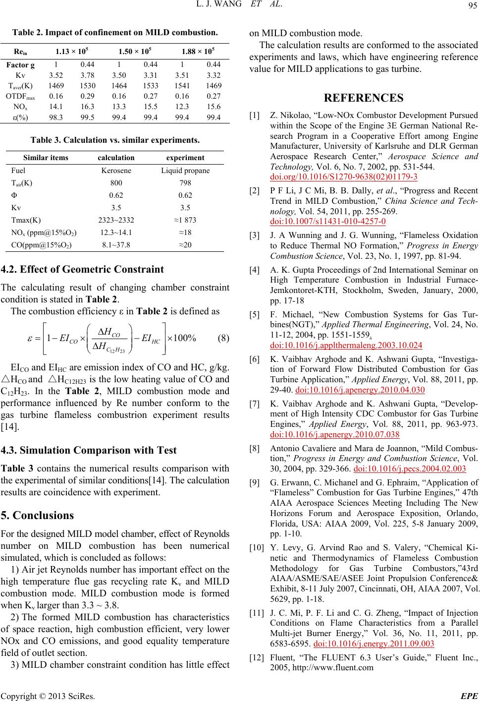
Table stion. 2. Impact of confinement on MILD combu
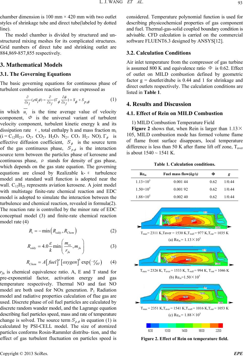
Rein 1.13 × 10
51.50 × 10
5 5
1.88 × 10
Fg actor 1 0.44 1 0.44 1 0.44
Kv 3. 523.78 3. 503.31 3. 513.32
T)
aver(K 1469 1530 1464 1533 1541 1469
OTDFmax 0.16 0.29 0.16 0.27 0.16 0.27
NOx 14.1 16.3 13.3 15.5 12.3 15.6
ε(%) 98.3 99.5 99.4 99.4 99.4 99.4
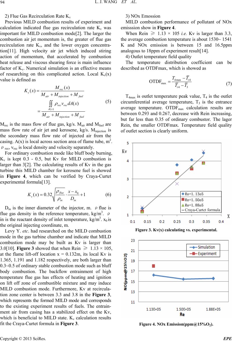
Table 3. Calculation vs. similar experiments.
Similar items calculation experiment
FueL l Kerosene iquid propane
Tair(K)
23232
15%O2)
800 798
Φ 0.62 0.62
Kv 3.5 3.5
Tmax(K)3~23 1 873
NOx (ppm@12.3~14.1 18
CO(ppm@15%O2) 8.1~37.8 20
4.2. Effect of Geometric Constraint
ber const
Table 2 is defined as
The calculating result of changing chamraint
condition is stated in Table 2.
The combustion efficiency ε in
12 23
1 100%
CO
CO HC
CH
H
EI EI
H


 






(8)
EICO and EIHC are emission index of CO and HC,
4.3. Simulation Comparison with Test
arison with
5. Conclusions
LD model chamber, effect of Reynolds
effect on the
tion has characteri
onstraint condition has little effect
conformed to the associated
ex
REFERENCES
[1] Z. Nikolao, “Lvelopment Pursued
g/kg.
HCO and HC12H23 is the low heating value of CO and
C12H23. In the Table 2, MILD combustion mode and
performance influenced by Re number conform to the
gas turbine flameless combustrion experiment results
[14].
Table 3 contains the numerical results comp
the experimental of similar conditions[14]. The calculation
results are coincidence with experiment.
For the designed MI
number on MILD combustion has been numerical
simulated, which is concluded as follows:
1) Air jet Reynolds number has important
high temperature flue gas recycling rate Kv and MILD
combustion mode. MILD combustion mode is formed
when Kv larger than 3.3 ~ 3.8.
2) The formed MILD combusstics
of space reaction, high combustion efficient, very lower
NOx and CO emissions, and good equality temperature
field of outlet section.
3) MILD chamber c
on MILD combustion mode.
The calculation results are
periments and laws, which have engineering reference
value for MILD applications to gas turbine.
ow-NOx Combustor De
within the Scope of the Engine 3E German National Re-
search Program in a Cooperative Effort among Engine
Manufacturer, University of Karlsruhe and DLR German
Aerospace Research Center,” Aerospace Science and
Technology, Vol. 6, No. 7, 2002, pp. 531-544.
doi.org/10.1016/S1270-9638(02)01179-3
[2] P F Li, J C Mi, B. B. Dally, et al., “Progress and Recent
Trend in MILD Combustion,” China Science and Tech-
nology, Vol. 54, 2011, pp. 255-269.
doi:10.1007/s11431-010-4257-0
[3] J. A Wunning and J. G. Wunning, “Flameless Oxidation
on
l, “New Combustion Systems for Gas Tur-
to Reduce Thermal NO Formation,” Progress in Energy
Combustion Science, Vol. 23, No. 1, 1997, pp. 81-94.
[4] A. K. Gupta Proceedings of 2nd International Seminar
High Temperature Combustion in Industrial Furnace-
Jemkontoret-KTH, Stockholm, Sweden, January, 2000,
pp. 17-18
[5] F. Michae
bines(NGT),” Applied Thermal Engineering, Vol. 24, No.
11-12, 2004, pp. 1551-1559.
doi:10.1016/j.applthermaleng.2003.10.024
[6] K. Vaibhav Arghode and K. Ashwani Gupta, “Investiga-
tion of Forward Flow Distributed Combustion for Gas
Turbine Application,” Applied Energy, Vol. 88, 2011, pp.
29-40. doi:10.1016/j.apenergy.2010.04.030
[7] K. Vaibhav Arghode and K. Ashwani Gupta, “Develop-
ment of High Intensity CDC Combustor for Gas Turbine
Engines,” Applied Energy, Vol. 88, 2011, pp. 963-973.
doi:10.1016/j.apenergy.2010.07.038
[8] Antonio Cavaliere and Mara de Joannon, “Mild Combus-
tion,” Progress in Energy and Combustion Science, Vol.
30, 2004, pp. 329-366. doi:10.1016/j.pecs.2004.02.003
[9] G. Erwann, C. Michanel and G. Ephraim, “Application of
G. Arvind Rao and S. Valery, “Chemical Ki-
and C. G. Zheng, “Impact of Injection
“Flameless” Combustion for Gas Turbine Engines,” 47th
AIAA Aerospace Sciences Meeting Including The New
Horizons Forum and Aerospace Exposition, Orlando,
Florida, USA: AIAA 2009, Vol. 225, 5-8 January 2009,
pp. 1-10.
[10] Y. Levy,
netic and Thermodynamics of Flameless Combustion
Methodology for Gas Turbine Combustors,”43rd
AIAA/ASME/SAE/ASEE Joint Propulsion Conference&
Exhibit, 8-11 July 2007, Cincinnati, OH, AIAA 2007, Vol.
5629, pp. 1-18.
[11] J. C. Mi, P. F. Li
Conditions on Flame Characteristics from a Parallel
Multi-jet Burner Energy,” Vol. 36, No. 11, 2011, pp.
6583-6595. doi:10.1016/j.energy.2011.09.003
[12] Fluent, “The FLUENT 6.3 User’s Guide,” Fluent Inc.,
2005, http://www.fluent.com
Copyright © 2013 SciRes. EPE
L. J. WANG ET AL.
Copyright © 2013 SciRes. EPE
96
. Ephraim, “Application of
[13] R. Curtet, “Combust Flame,” Vol. 2, 1958, pp. 383-411.
[14] G. Erwann, C. Michael and G
AIAA
‘Flameless’ Combustion for Gas Turbine Engines,” 47th
Aerospace Science Meeting Including The New
Horizones Forum and Aerospace Exposition, Orlando,
Florida, USA, 2009, pp. 1-10.