Energy and Power Engineering, 2013, 5, 78-82
doi:10.4236/epe.2013.54B015 Published Online July 2013 (http://www.scirp.org/journal/epe)
Design and Performance of Brushless Doubly-fed Machine
Based on Wound Rotor with Star-polygon Structure
Chaohao Kan
College of Electrical & Automatic Engineering, Hefei University of Technology, Hefei, China
Email: kchthw@126.com
Received September, 2012
ABSTRACT
The star-polygon bru shless doubly-fed machine (SPBDFM) is a new type of wound-rotor machine and is attractive fo r
variable-speed constant-frequency shaft generation system. The structure of rotor for the machine may b e impro v ing the
conductor availability of th e rotor windings. The kirchhoff laws is employed to illuminate the princip le and some com-
binations of different slots and poles are presented as the examples. Harmonic analysis is also employed to analyze the
magnetic motive force (MMF) waveform of rotor winding with the structure of star- polygon. Finally, the results are
used to reveal that the SPBDFM is attractive for shaft generation system.
Keywords: Polygon; BDFM; Wound Rotor; Magnetic Motive Force
1. Introduction
The brushless doubly-fed machine (BDFM), having ad-
vanced recently, is a new type AC-excited motor, with
the characteristics of synchronous motor and induction
motor. There are two sets of symmetrical AC windings in
the stator: the control winding with 1 pole-pair is
connected via a power electronic converter and the pow-
er winding with 2 pole-pair is connected directly to
the grid, and a set of symmetrical AC windings in the
rotor. There haven’t the direct contact between the two
sets of stator wind ings on voltage or cur rent, but through
the couple of rotor magnetic field to realize modulation
of two sets of stator rotating magnetic field which have
different pole-pair, achieving the motor electrical and
mechanical energy conversion and transmission [1-4]. A s
a generator, the variable-speed constant-voltage constant-
frequency sound generation features make its in the wind
power generation, marine shaft power generation area; as
a motor when the precise timing of its features make it in
the higher speed requirements of place has a broad ap-
plicatio n p rospect s.
p
p
The structure of rotor winding is a k ey factor affecting
the performance of a BDFM, therefore rotor winding
needs to be specially desig ned to achiev e the requirement
that rotor MMF couple the MMF generated by the stator
control winding and power winding [5-8]. When a rotor
with r
Z
bars is subjected to rotating magnetic fields of
1 pole-pair, the indu ced rotor MMF contains main slot
spatial harmonic of 1r pole-pair. When 1
ppZ0
r
pZ
,
the rotation direction of the harmonic field is against the
main field of pole-pair relative to the rotor. Obvi-
ously, choose 21r
1
p
pZp
p
precisely to meet synchro-
nous operation requirement with the BDFM, therefore,
the rotor can choose 12
p
slots.
While the sum of stator pole-pair numbers is small, if
the number of rotor slots is choice as 12
, the in-
duced harmonic MMFs of rotor winding is abundant, the
leakage reactance may be weaken by increasing the slot
number. When the rotor slot number increase to r
pp
Z
12
K
pp (
K
a positive integer), We have, by the
principles of BDFM winding design, each
adjacent
rotor slot is a basic unit, which is a minimum slot number
group, named the smallest slot number group, also it is
known as a phase of rotor winding. Obviously, each
smallest slot number group has same winding connection
means.
Current the design, it is known as the ‘nested-loop’
design. As a example, a rotor 54 slots, 1/2 pole-pairs
‘nested-loop’ is shown as Figure 1. It has 3 nests, and
there are 6 loops in each nest.
Figure 1. bdfm with rotor 54slots 1/2- pole pair winding
with the connection of nested loop.
Copyright © 2013 SciRes. EPE
C. H. Kan 79
Both the nested loop structure and the reluctance
structure of BDFM are “magnetic field” type which by
adjusting the flow path to achieve the rotor to couple the
magnetic field of the two sets of stator winding. Because
of the air gap is sinusoidal alternating magnetic field,
rotor winding could not preferable realized coupling two
kinds of stator magnetic field only by change the mag-
netic flux path. the “magnetic field” type structure has
defect, such as follows: abundant harmonic MMFs; strong
sub-pressure effect; for the relatively small pole-pair
number, the winding pitch (nested loop) or the equivalent
winding pitch (reluctance) is smaller, especially in the
difference between two pole-pair is big, therefore, it is
weak that the effect of magnetic coupling for the smaller
of the pole - p a ir number.
In this paper, the rotor winding with “star-polygon”
structure of the BDFM is presented. In the novel machine,
the “star-polygon” topology is employed, by using this
method, the phase current vector of rotor winding will
shift a specified angle, and this shift will change the vec-
tor of rotor winding MMF, and improve the magnetic
field distribution.
2. Structure and Working Principle of the
Rotor
By Kirchhoff law, it’s obviously that the phase current
and the line current have a certain phase angle difference
in time domain for the connection of polygon circuit.
And motor rotor windings also have a certain phase dif-
ference in space. If using the space on the phase differ-
ence to compensate for the phase difference in time do-
main, it may be making the two parts of windings MMF
generated by superimposed in space, then the windings
are star - polygon connection can increase the number of
pole-pair corresponding phase windings of the distribu-
tion coefficient, thus to improve the utilization of con-
ductors.
To achieve the above functions, the specific winding
connection is requ ired. As mentioned above, for the con-
trol winding 1 pole-pair and the power winding
pole-pair, the rotor winding is divided into 12
p2
p
pp
phases and each phase winding is divided into two
groups. The subscripts d, s denote this two groups. The
rotor winding parameters of one phase are defined as
follows: is the coil win ding number of the polygon
part and rs is the coil winding number of the star part;
rd is each phase winding turns per coil turns of the
polygon part and rs is each phase winding turns per
coil turns of the star part. The star-polygon structure of
the rotor winding is shown in Figure 2.
rd
N
N
WW
As shown in Figure 2, rdi and rsi are the ith
phase rotor winding induction electromotive force of the
polygon part an d star part respectively, where i = 1,2, ...,
E E
1rs
E

rsm
E

2rs
E

1rd
E

rdm
E

2rd
E

Figure 2. Structure of wound rotor in the form of star- po-
lygon.
m. The number of rotor winding phase is 12
mp p
and 12
pp
is supposed.
The principle of the rotor winding with the star-poly-
gon structure is illustrated as follows. When the stator
windings of 1 pole-pair are imposed with the currents,
the gap space will generate the 1 pole-pair air-gap
magnetic field [9,10]. The expression of each phase in-
duced electromotive force for the rotor windings is given
by Equation (1).
pp







1
211
11
11
211 1
11 1
0
1
1
rd rd
rd rd
rdm rd
rs rs
rs rs
rsm rs
EE
EEp
EEmp
EEp
EEpp
EEmpp



 

 
 
(1)
where rd and rs are each phase induced electromo-
tive force amplitude of the polygon part winding and the
star part winding respectively. Since each phase rotor
winding is connected in the same manner, the amplitude
of the induction electromotive force for the star part and
polygon part are equal respectively. 1
E E
is the mechani-
cal rotor shaft angle.
is the angle between the me-
chanical axis of the star part and polygon part for one
certain phase rotor winding.
It can be seen from the symmetry of topological struc-
ture that the current of star part and polygon part are
symmetry distribution respectively. Using equal (1) the
rotor winding current may be written as
Copyright © 2013 SciRes. EPE
C. H. Kan
80







10
211 0
11 0
10
211 0
11 0
1
1
rd rd
rd rd
rdm rd
rs rs
rs rs
rsm rs
II
IIp
IImp
II
IIp
IImp






 
 

 
 
(2)
where rd
I
and rs
I
are the current amplitude which are
produced by the polygon part winding and the star part
winding of each phase respectively. 0
is the angle
which is between the electromotive force vector and the
current vector. By the simplification, we define00
.
It’s obvious that the angle 11
22
p
 (see appendix).
In order to ensure that the ampere conductors per slot are
the same value, the ratio of the current amplitude is
::
rd rsrsrd
I
IWW approximately.
The axis of polygon part for first-phase winding is
counted as the coordinate origin for the space angle. For
the vth MMF harmonic may be written as equal (3).

















11
21 1111
111 11
111
21111 11
1111
cos cos
cos cos
cos( 1)cos( 1)
cos cos
cos cos
cos( 1)
rd vdvr
rd vdvr
rdmv dvr
rs vsvr
rs vsvr
rsmv sv
fF vpt
fF vpptp
fF vpmptmp
fF vppt
fF vppptp
fF vpmpp

 
 
 
 


 




11
cos( 1)
rtm p

 
(3)
where dv
F
and
s
v
F
are the pulsating MMFs that are
produced by the polygon part winding and the star part
winding of each phase respectively. By the ratio of the
rotor winding current amplitude rd
I
and rs
I
, it can be
seen that rdrdvrs rsv
::
dv sv
F
FNkkN

 
, where rdv
and rsv are the polygon part winding and the star part
winding of the rotor winding vth harmonic winding fac-
tor respectively. r
k
k
is the frequency of the magnetic
field in the rotor reference frame, hence the rotor fre-
quencies in the referred circuit are equal in the magnitude.
When , the combination of m phase MMFs is 1v

1
11
111
cos
2
cos
2
d
pr
dr
mF
Ftp
mF tp p




(4)
when 21
vpp, the pole-pair of the combination of
phase is , because the 2 pole-pair magnetic field is
inverse with the pole-pair magnetic field in the ro-
tating direction, we have
2
pp
1
p


2
22
222
cos
2
cos
2
dp
pr
sp r
mF
Ftp
mF tp p




(5)
From equation (4) and (5), it is can be seen that the
angle of MMFs which are produced by star part and po-
lygon part of the same rotor phase winding are adjusted
as
. We have
11
11
12
1
22 0
222
ppp
mpp
m



 
(6)
Form the equation (4), (5) and (6), it is can be seen
that the MMF angle between star part and polygon part
of each phase is increased by
for 1 pole-pair,
which is bound to reduce the composite MMFs; and the
MMF angle that between star part and polygon part of
each phase is reduced by
p
for 2 pole-pair, which is
bound to increase the composite MMFs. Because
12
p
pp
, the decrease in value of 1 pole-pair MMF is
less than the increase in value of pole-pair MMF.
p
p2
When the three-phase symmetrical voltage sources
impose on the 2 pole-pair stator windings, it will form
2 pole-pair MMF in the air-gap magnetic field, ac-
cording to the equation (1) ~ (6), and the similar conclu-
sion can be proved: for 1 pole-pair, the MMF angle
that between star part and polygon part of each phase is
increased by
p
p
p
. For 2 pole-pair, the MMF angle that
between star part and polygon part of each phase is re-
duced by
p
.
To sum up, the two kinds of air gap magnetic field
produced by the 1 and 2 pole-pair rotor winding
are rotating in the opposite direction, and the angle be-
tween the magnetic of star part winding and the magnetic
of circular part winding will increase while the rotor
winding produces the 1 pole-pair magnetic field, or
reduce while the rotor winding produces the 2 pole-
pair magnetic field. Since 1, 2 are the fix number,
the angle
p p
p
pp
p
only has one value. If 12
, the sum of
windings distribution coefficients will increase. If 12
,
the sum of windings distribution coefficients of the
winding connected in the above mentioned method will
reduce. So it doesn’t fit for the rotor winding connection.
pppp
3. Prototype Test
The designed rotor winding has been wound in an
YZR225 induction machine, as shown in Figure 3(a).
The stator has 72 slots, in which two windings of 11p
and 22p
pole-pair are separately placed. The rotor
has 54 slot and its winding connection diagram is shown
in Figure 3(b), where y = 15.
Copyright © 2013 SciRes. EPE
C. H. Kan 81
As a comparison, the rotor winding connection dia-
gram in the general structure is shown in Figure 4.
It is listed in Table 1 that the comparison of harmonic
analysis for the resultant MMF produced by three kinds
of winding (as shown in Figure3(b), Figure 4 and Fig-
ure 1). The coil s pans are cho sen as 15 slo ts (y = 15) for
the former two.
As listed in Table 1, the rotor winding coefficient is
decreased by 0.091 as form 1 pole-pair, and the rotor
winding coefficient is increased by 0.128 as form 2 pole-
pair. Obviously, the star - polygon structure can improve
the overall utilization rate of the rotor windings effec-
tively. Comparable to nested loop winding, the winding
coefficient is decreased as form 1 pole-pair, just as form
2 pole-pair. But, the important, the star-polygon connec-
tion has significantly smaller in high harmonic MMFs.
(a) Prototype machine
3
42
15
39 40
3837
41
21
22
2019
23
10
11
8
7
12
46 47
44
43
48
28
29
2625
30
6
42
9
45
27
24
(b) Winding structure
Figure 3. Prototype machine and star-polygon structure of
the 54 slots 1/2 pole-pair prototype.
3
42
1
5
39 40
38
37
41
21
22
20
19
23
6
42
24
10
11
8
7
12
46 47
44
43 48
28 29262530
9
45
27
Figure 4. A wound-rotor 54 slots and 1/2 pole pairs winding
with a general structure.
Table 1. Comparison of the results of MMF harmonic anal-
ysis of rotor winding with a structure in the form of
star-polygon, general, and nested LooP.
star – polygon general nested loop
Pole-p
airs Winding
factor Resultant
MMF% Winding
factor Resultant
MMF%
Winding
factor Resultant
MMF%
1 0.615 –149.4 0.706 -202.7 0.642 –139.8
2 0.824 100 0.696 100 0.918 100
4 0.021 –1.29 0.042 -3.04 0.204 -11.1
5 0.047 2.28 0.093 5.37 0.255 11.1
7 0.043 –1.48 0.036 –1.48 0.296 –9.21
8 0.067 2.03 0.077 2.76 0.072 1.97
10 0.055 –1.33 0.063 –1.80 0.008 –0.18
11 0.028 0.62 0.024 0.62 0.124 2.45
(a) Magnetic field
00.02 0.040.06 0.080.1
-200
-150
-100
-50
0
50
100
150
200
time(sec)
voltage(V)
v1
v2
v3
v4
v5
v6
(b) Voltage curve
Figure 5. magnetic field and voltage curve as 2 pole-pair
output 5 kw.
800 1000 1200
0
20
40
60
80
line voltage of control
V
speed
rpm
(a) Control voltage
80090010001100 1200
10
15
20
current in control
A
speed, rpm
(b) Control current
Figure 6. Control voltage and control current as power
winding OUTPUT 5 KW (cosφ = 1).
In the experiment, the 2 pole-pair winding is used as
the power winding with a line voltage of 200 V rms (the
phase voltage 115.5 V rms correspond). We keep the
power winding output 5 kW (cos 1
). As the rotor
speed is 1200 rpm, the magnetic field is shown as in
Figure 5(a); the power winding voltage (named v1, v2
and v3) and contro l voltage (named v4, v5 and v6) curv e
are shown as in Figure 5(b) based on FE analysis. As the
Copyright © 2013 SciRes. EPE
C. H. Kan
Copyright © 2013 SciRes. EPE
82
[1] P. C. Roberts and R. A. McMahon, “Performance of
BDFM as Generator and Motor, IEE Proceedings, Elec-
tric Power Application, Vol. 153, No. 2, 2006, pp.
289–299.
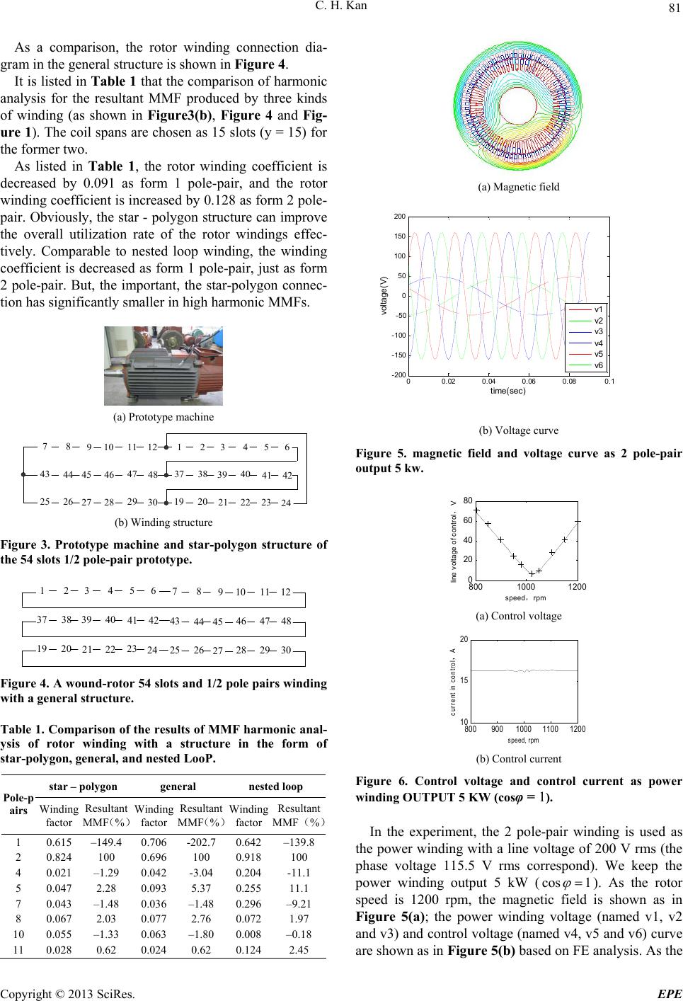
rotor speed is from 800 to 1200 rpm, the control voltage
vs. speed is shown in Figure 6(a); the control current vs.
speed is shown in F igure 6( b ).
As shown in Figure 6(a), the experimental data are
consistent with the calculated results based on FE analy-
sis. Obviously, the star-polygon BDFM can realize the
function of variable-speed constant-voltage constant-
frequency generation.
[2] S. Williamson, A. C. Ferreira and A. K. Wallace, “Gener-
alized Theory of the BDFM. Part 2: Model Verification
and Performance,” IEE Proceedings- Electric Power Ap-
plication, Vol. 144, No. 2, 1997, pp. 123–129.
doi:10.1049/ip-epa:19971052
[3] A. K. Wallace, P. Rochelle and R. Spee, “Rotor Modeling
and Development for BDFMs,” Conference of Record
of the International Conference on Electrical Machines,
Cambridge, Vol. 1, 1990.
4. Conclusions
This paper has presented, for the first time, a new type
rotor winding connection, named star-polygon, for
BDFM. The BDFM with “star- polygon” structure of
rotor windings has the following five characteristics: 1, It
is increased that the rotor winding distribution coefficient
which corresponding to the stator power windings; 2, A
set of rotor slot conductors is used repeatly, improving
the actual utilization of the rotor slot conductors; 3, The
choice of winding pitch is freedom; 4, The connection of
rotor winding is flexible; 5, The content of harmonic
MMFs is low. So this new type structure of rotor wind-
ings has great development prospects.
[4] X. Wang and P. C. Roberts, “Optimization of Bdfm Sta-
tor design Using an Equivalent Circuit Model and a
Search Method,” In Proc, IEE 3th Int. Conf. Power Elec-
tronics, Machines and Drives, Dublin, Ireland, 2006, pp.
606-610.
[5] X. Wang, R. A. McMabon and P. J. Tavner, “Design of
the Brushless Doubly-fed (induction) Machine,” IEEE
Interaction Election Machines &Drives Conference,
IEMDC’07, Vol. 2, 2007, pp.1508-1513.
[6] X. F. Wang, “A New BDFM with a Wound-rotor Chang-
ing-pole Winding,” Proceedings of the CSEE, Vol. 23,
No. 6, 2003, pp. 108-111.
5. Acknowledgements [7] S. C. Yang, “Feature of Electromagnetic Design for
BDFMs,” Proceedings of the CSEE, Vol. 21, No. 7, 2001,
pp. 107-110.
This work was supported by the Surface of Natural Sci-
ence Fund Program projects of Anhui Province (NO.12
08085ME62), by the Doctoral Degree in Special Re-
search Fund Program projects of hfut (NO. 2011HGBZ-
0935).
[8] F. G. Zhang, F. X. Wang and Z. Wang, “Comparative
Experiment Study on the Performance of Doubly-fed),”
Proceedings of the CSEE, Vol. 22, No. 4, 2002, pp.
52-55.
The authors wish to thank the China Changjiang Na-
tional Shipping Group Motor Factory for the provision of
the prototype machine and fabrication of the rotor.
[9] C. H. Kan and X. F. Wang, “Harmonic Anslysis for
Wound-rotor Winding in Induction Manchine,” Large
electric manchine and hydraulic turbine., Vol. 4, 2007,
pp. 18–23.
[10] S. Z. Xu, “Windings Theory of A.C. Machines,” Publish-
ing House of Machinery Industry, 1985.
REFERENCES
Appendix phase are symmetry, the value of
is not a result of
the chosen reference point of change.
The parameters compute of
The current vectors, such as 1rd
I
, 2rd
I
and 1rs
I
, in-
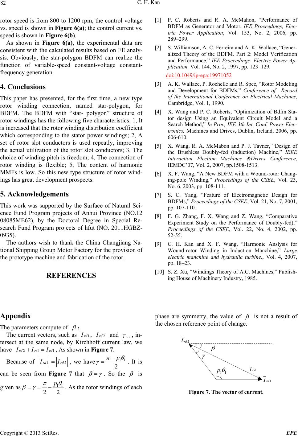
tersect at the same node, by Kirchhoff current law, we
have 21rdrs rd
1rd
I
2rd
I
1rs
I
11
p
1
I
II, As shown in Figure 7.
Because of 1rdrd 2
I
I, we have11
2
p
. It is
can be seen from Figure 7 that
. So the
is
given as11
22
p

 . As the rotor windings of each Figure 7. The vector of current.