Paper Menu >>
Journal Menu >>
 Open Jo urnal of Applied Sciences, 2013, 3, 1-4 doi:10.4236/ojapps.2013.32B001 Published Online June 2013 (http://www.scirp.org/journal/ojapps) Copyright © 2013 SciRes. OJAppS Mechanics Analysis of Overhead Transmission Lines Based On-line Monitoring Lili Dai, Yongli Zhu, Zehui Liang School of Electrical and El ectronic Engineering, North China Electric Power University, Baoding,China Email: lilidai070582@126.com Received 2013 ABSTRACT At present, the on-line monitoring i s widely applie d to the power line monitoring. In t his pa per, a new mechanical cal- culation model is established according to the on-line monitoring. And this model is based on the parameters that ten- sion se nsor s a nd angle sensors on suspended points detect, and combines with the parameters of the wire itself, and also considers the deflection angel of wires due to wind. In this model, mechanics parameters of wires are turned into the new coordinate plane after deflection angel of wires due to wind, or wind age ya w plane . A statics tension balance equa- tion is built in the vertica l direction o f the new windage ya w plane. According to the theoretical analysis and algorithm, we ve rify the accuracy of this newly developed mechanical calculation model. Keywords: Overhe ad Transmission Li ne; O n-line Monitoring; Mechanical Analysis; Tension; A ng le ; I c ing; Windage Yaw 1. Introduction Affected by climate, macrophotography and meteorolo- gical conditio ns, icing of tra nsmission line occurs widely in China and causes ice disasters accident such as short terms, pour towers [1]. For example, in January 2008, parts of Southern China suffered a rare sleet weather re- sulting in widesp read icing of trans mission line s, and ice thickness of some towers obviously went beyond line mechanical carrying capacity. The heavy ice cover even caused the collapse of towers, which not only strongly affected and threatened the safety and stability of the power grids but also caused huge economic loss[2]. In on- line monitoring sys tems, tensio n se nsors a nd an- gle sensors are the bare essentials. Tension and angle of suspended points can reflect the role of the wind on con- ductors and the changes of conductors state. This paper detects the steady state icing of overhead power lines mainl y thro ugh t he co mbinati on of a xial t ensio n, deflect- tion ange l and swin g angle of suspensi on point. 2. Static Mechanics Analysis Model of the Straig- ht Tower In engineering calculations, they often overlook the ri- gidity of overhead conductors as flexible cable. And in fact, we assume that the wire load is evenly distributed along the d eflection span, for the reason that the differen- ce between the arc length of the wire and the distance of the t wo sus pen sion p oi nts i n a sp an is ver y small. For the above reasons,the inclined parabola formulas can be ap- plied in the calcu lation of the wires, and the error is with- in the a llowable range in the engineering.[3] 2.1. Statics Mechanics Analysis in the Vertical Plane The mechanical model of the overhead tra n smi s sio n li nes in the condition of no wind and no ice is in Figure 1. Shown in the Figure 1, l is the span length; h is the height difference between the two neighboring towers; β is the angle of height difference between the two neighboring suspension points; V l is the distance betwe- en the lowest points and the main tower; γ is the load of the wire itself. B C A 1 l 2 l 1 h 2 h 1 β 2 β γ 1V l 2V l Figure 1.Transmission line model without external load in vertical pla ne of towers. 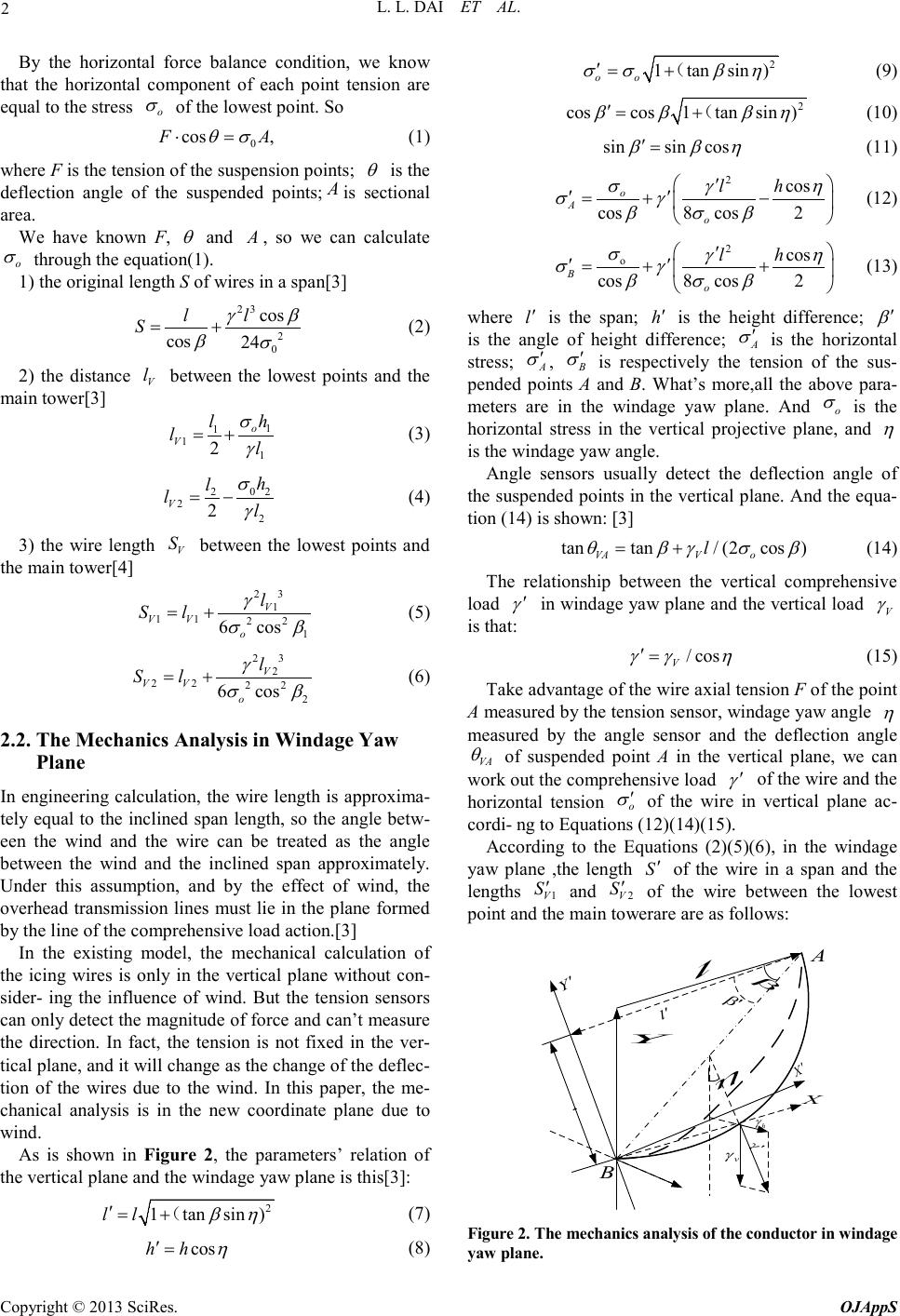 L. L. DAI ET AL. Copyright © 2013 SciRes. OJAppS 2 By the horizontal force balance condition, we know that the horizontal component of each point tension are equal to the stress o σ of the lowest p oint. So 0 cos , FA θσ ⋅= (1) where F is the tension of the suspension points; θ is the deflection angle of the suspended points; A is sectional area. We have known F, θ and A , so we can calculate o σ through the equation(1). 1) the original length S of wires i n a span[3] 23 2 0 cos cos 24 ll S γβ βσ = + (2) 2) the distance V l between the lowest points and the mai n tower[3] 1 1 11 2o V h l ll σ γ = + (3) 02 2 22 2 V h l ll σ γ = − (4) 3) the wire length V S between the lowest points and the main tower[4] 23 1 11 22 1 6 cos V VV o l Sl γ σβ = + (5) 23 2 22 22 2 6 cos V VV o l Sl γ σβ = + (6) 2.2. The Mechanics Ana ly s is in Windage Yaw Plane In engineering calcula tion, the wire length is approxima- tely equal to the inclined span length, so the angle betw- een the wind and the wire can be treated as the angle between the wind and the inclined span approximately. Under this assumption, and by the effect of wind, the overhead transmission lines must lie in the plane formed by the line of the comprehensive load action.[3] In the existing model, the mechanical calculation of the icing wires is only in the vertical plane without con- sider- ing the influence of wind. But the tension sensors can only detect the magnitude of force and can’t measure the direction. In fact, the tension is not fixed in the ver- tical plane, and it will change a s the c ha nge of the d efle c- tion of the wires due to the wind. In this paper, the me- chanical analysis is in the new coordinate plane due to win d. As is shown in F ig ure 2, the parameters’ relation of the vertical plane and the windage yaw plane is this[3]: 2 1tansin )ll βη ′= +( (7) cos hh η ′ = (8) 2 1tansin ) oo σσ βη ′= + ( (9) 2 coscos1tansin ) β ββη ′= +( (10) sinsin cos β βη ′ = (11) 2 cos cos8 cos2 o Ao lh σγη σγ β σβ ′ ′′ =+− (12) 2 o cos cos8 cos2 Bo lh σγη σγ β σβ ′ ′′ =++ (13) whe re l′ is the span; h′ is the height difference; β ′ is the angle of height difference; A σ ′ is the ho rizontal stress; A σ ′ , B σ ′ is respectively the tension of the sus- pended points A and B. What’s more,all the above para- meters are in the windage yaw plane. And o σ is the horizontal stress in the vertical projective plane, and η is the windage yaw angle. Angle sensors usually detect the deflection angle of the suspended points in the vertical plane. And the eq ua- tion (14) is shown: [3] tantan/(2cos) VAV o l θβγσ β = + (14) The relationship between the vertical comprehensive load γ ′ in wind age yaw plane and the vertical load V γ is that: / cos V γγ η ′= (15) Take advantage of the wire axial tension F of the point A measured by the tension sensor, windage yaw angle η measured by the angle senso r and the deflection angle VA θ of suspended point A in the vertical plane, we can work out the comprehensive load γ ′ of the wire and the horizontal tension o σ ′ of the wire in vertical plane ac- cordi- ng to Equatio ns (12)(14)(15). According to the Equations (2)(5)(6), in the windage yaw plane ,the length S′ of the wire in a span and the lengths 1V S′ and 2V S′ of the wire between the lowest point and the main towerare are as follows: l′ h l η h γ γ ′ v γ Y Y′ X β β ′ X′ A B Figure 2. The mechanics analysis of the con ductor in windage yaw plane.  L. L. DAI ET AL. Copyright © 2013 SciRes. OJAppS 3 23 2 cos cos 24 o ll S γβ βσ ′ ′′′ ′= + ′′ (16) 23 1 11 22 1 6 cos V VV o l Sl γ σβ ′′ ′′ = +′′ (17) 23 2 22 22 2 6 cos V VV o l Sl γ σβ ′′ ′′ =+ ′′ (18) 2.3. The Mechanics Analysis of Icing Wires in the New Coordinate Plane Due To Wind Because of the change of meteorological conditions, the conductor tensions in different spans will change by the parameters of themse lves. And it will result that wires of different spans have d i ffe re nt ho riz ontal tensions, a nd the suspended points will occur horizontal movement until the horizontal tensions of the neighbo uring spans are equal. The model of the icing wires in the windage yaw plane is s ho wn a s Figure 3, a nd the po sition o f insulator s and wires is described in Figure 4. In order to simplify the calculation, we assume that t he deflection a ngle of insulator c hain is the sa me to t he sus- pended point’s. And considering that the difference of θ ′ and A θ ′ is small, we assume that A θθ ′′ ≈ and V VA θθ ′′ ≈. B′ C′ A′ 1 l′ 2 l′ 2 h′ 1 β ′ 2 β ′ γ ′ 1V l′ 2V l′ 1 h′ ′ θ Figure 3. The calculating model of icing wires in t he windage yaw plane. θ ′ A θ ′ α Figure 4. The system of insulator-wire in the new coordi- nate plane due to wind. According to the above hypothesis, the deflection an- gle θ ′ and the windage yaw angle η and the deflec- tion angle VA θ of the suspended point A in the vertical plane have this relationsh ip[5]: 22 cos1/(cos1tantan) VA θη ηθ ′= ++ (19) For the suspended point A, the equation about the ver- tical load V γ and the vertical component of the tension A F is shown as: [ ] V1 V2 cosA( S S)/cos AV F θγ η ′ ′′ = + (20) whe re V γ is the comprehensive vertical load of the ic- ing wir e s, and V ice γ γγ = +; ice γ is the load of the icing wires . The equation (20) can deduce the load of icing wire: ( ) ice 12 cos cos A VV F S SA θη γγ ′ = − ′′ + (21) According to the calculation icing load and the shape of icing conductor which is set to a uniform cylindrical by the t ra nsmi ssio n li ne d esig n sta nda rd o f po wer s yste m, then the calculation formula of icing thickness is as fol- lows: 2 ice 4 0.5 9.8 A b dd γ πρ = +− (22) whe re d is the calculation diameter of conductor; b is the icing thickness; ρ is the icing density, and it’s usually equal to 0.9 g/m3. 3. Demonstration We will verify the validity of this model by calculating the wind load wind γ of the icing wire [6]. It’s called the wind load wind γ of icing wires that ic- ing wires of per meter and per square millimeter with- stand wind press load.The expression of wind γ algorithm is as follows: 23 0.6125 (2)10 wind Cbd A αυ γ − + = × (23) whe re α is the non-uniformn coefficient of wind speed, the values are shown in Table 1; υ is the design wind speed; C is the figure coefficient of wind load, and it’s usually equal to 1.2. If the ratio of wind γ and V γ is equal to tan η , then the model in this p a per is validity. Table 1. The value of in differe nt conditions υ (m/s) ≤ 20 20~30 30~35 ≥ 35 α 1.0 0.85 0.75 0.70  L. L. DAI ET AL. Copyright © 2013 SciRes. OJAppS 4 4. Conclusions In this paper, we just build a model in theory that appli- cable to the usual on-line monitoring. As fo r as the accu- racy and practicab ility, practical examples have yet to prove the model. If the model is correct, it will be appl- icable to the co nditions that monitorin g systems have not image detection or that the weather is freezing and af- fects the icing monitoring. The new model can get icing information, so that we can timely de-icing if the icing is beyond line mechanical carrying capacity and guarantee the normal use of elec- tric transmission wires in the freezing climate. REFERENCES [1] X. L. Jiang and H. Yi, “Transmission Line Icing and Pro- tection,” China Electric Power Press, Beijing, 2002. [2] H. Hou, X. G. Yin, Q. Q. Chen, et al., “Review on the Wide Area Blackout of 500 kV Main Power Grid in Some Areas of Sout h China in 200 8 Snow Disaster,” Au- tomation of Electric Power Systems, Vol. 32, No. 8, 2008, pp. 12-15. [3] X. T. Shao, “The Wire’s Mechanical Calculion of Over- head Transmission Line,” Chi na Water Po wer Press, Bei- jing, 2003. [4] B. Z. Li, “Stringing Technique Calculation Principle of High Voltage Overhead Transmission Line,” China Elec- tric Power Press, B e ijing, 2002. [5] L. Yan g, Y. P. Hao, W. G. Li, D. Dai, L. C. Li, G. H. Zhu and B. Luo, “A Mechanical Calculation Model for On-line Icing-monitoring System of Overhead Transmis- sion Lines,” Proceedings of the CSEE, Vol. 30, No.19, 2010, pp.100-105. [6] Y. X. Lu and Y. Zhou, “Simple Models for Calculating Weight of Ice Accretion on Tran smission Lines,” East China Electric Power, Vol. 37, No. 3, 2009, pp. 0433-0435. |