Paper Menu >>
Journal Menu >>
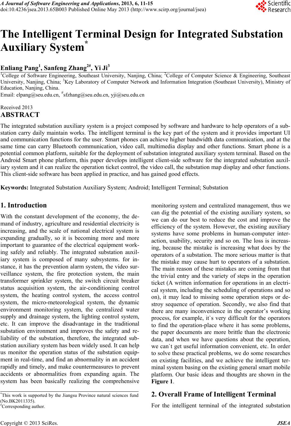 A Journal of Software Engineering and Applications, 2013, 6, 11-15 doi:10.4236/jsea.2013.65B003 Published Online May 2013 (http://www.scirp.org/journal/jsea) 11 The Intelligent Terminal Design for Integrated Substation Auxiliary System* Enliang Pang1, Sanfeng Zhang2#, Yi Ji3 1College of Software Engineering, Southeast University, Nanjing, China; 2College of Computer Science & Engineering, Southeast University, Nanjing, China; 3Key Laboratory of Computer Network and Information Integration (Southeast University), Ministry of Education, Nanjing, China. Email: elpang@seu.edu.cn, #sfzhang@seu.edu.cn, yji@seu.edu.cn Received 2013 ABSTRACT The integrated substation auxiliary system is a project composed by software and hardware to help operators of a sub- station carry daily maintain works. The intelligent terminal is the key part of the system and it provides important UI and communication functions for the user. Smart phones can achieve higher bandwidth data communication, and at the same time can carry Bluetooth communication, video call, multimedia display and other functions. Smart phone is a potential common platform, suitable for the deplo yment of substation integr ated aux iliary syste m terminal. Based on th e Android Smart phone platform, this paper develops intelligent client-side software for the integrated substation auxil- iary system and it can realize the operation ticket control, the video call, the substation map display and other functions. This client-side software has been applied in practice, and has gained good effects. Keywords: Integrated Substation Auxiliary System; Android; Intelligent Terminal; Substation 1. Introduction With the constant development of the economy, the de- mand of industry, agriculture and resid ential electricity is increasing, and the scale of national electrical system is expanding gradually, so it is becoming more and more important to guarantee of the electrical equipment work- ing safely and reliably. The integrated substation auxil- iary system is composed of many subsystems. for in- stance, it has the prevention alarm system, the video sur- veillance system, the fire protection system, the main transformer sprinkler system, the switch circuit breaker status acquisition system, the air-conditioning control system, the heating control system, the access control system, the micro-meteorological system, the dynamic environment monitoring system, the centralized water supply and drainage system, the lighting control system, etc. It can improve the disadvantage in the traditional substation environment and improves the safety and re- liability of the substation, therefore, the integrated sub- station aux iliary syste m h as been wid ely u sed . It can h elp us monitor the operation status of the substation equip- ment in real-time, and find an abnormality in an accident rapidly and timely, and make countermeasures to prevent accidents or abnormalities from expanding again. The system has been basically realizing the comprehensive monitoring system and centralized management, thus we can dig the potential of the existing auxiliary system, so we can do our best to reduce the cost and improve the efficiency of the system. However, the existing auxiliary systems have some problems in human-computer inter- action, usability, security and so on. The loss is increas- ing, because the mistake is increasing what does by the operators of a substation. The more serious matter is that the mistake may cause hurt to operators of a substation. The main reason of these mistakes are coming from that the trivial entry and the variety of steps in the operation ticket (A written information for operation s in an electri- cal system, including the scheduling of operations and so on), it may lead to missing some operation steps or de- stroy sequence of operation. Secondly, we also find that there are many inconvenience in the operator’s working process, for example, it`s very difficult for the operators to find the operation-place where it has some problems, the paper documents are more brittle than the electronic data, and when we have questions about the operation, we can`t get useful information convenient, etc. In order to solve these practical problems, we do some researches on existing facilities, and we achieve the intelligent ter- minal system basing on the existing general smart mobile platform. Our basic ideas and thoughts are shown in the Figure 1. 2. Overall Frame of Intelligent Terminal *This work is supported by the Jiangsu Province natural sciences fund (No.BK2011335). #Corresponding author. For the intelligent terminal of the integrated substation Copyright © 2013 SciRes. JSEA  The Intelligent Terminal Design for Integrated Substation Auxiliary System 12 auxiliary system, we chose Android mobile equ ipment as the hardware platform, and the software system is de- signed by ourselves. On the one hand, in order to obtain the operation tickets, the terminal system should contact with the operation ticket informatio n manage ment server, on the other hand, it also needs to be connected with the video SIP proxy server, so the operator can contact with other colleagues and solves the problems in the work timely. We use C/S network structure between the ter- minal and the server, and realized the connection via WiFi. Meanwhile, in order to make the terminal system operate easily and have good scalability, we also de- signed the system architecture of the terminal. It is shown in Figure 2. 1) GUI: The user interface layer is on the top of the auxiliary system's structure. The purpose is to provide some simple, beautiful, convenient and friendly inter- faces with users. The layer includes the login interface, the operation ticket display interface, the video call in- terface, the substation map interface, and the system setup interface, etc. All of that, the operation ticket inter- face is the most important for our intelligent terminal system, and it can mainly restrict the operation in order to ensure the integrity of the process, which means that the current step must be completed before they can get the next step. 2) Business logic processing layer: Business logic processing layer is the most important of the intelligent terminal system. All business processing depend on this layer. This layer respond the events from the user inter- face and carry out the corresponding business logic processing, then control the terminal interface’s update or jump. Besides, this layer can also detect the update of data from the data storage layer and synchronized to the user interface, it is mainly used for display of the video real-time. At present the business logic layer is mainly composed of four function modules, they are the Blue- tooth event response module, the video data analysis Figure 1. Function overview map. Figure 2. The design of the overall framework. Copyright © 2013 SciRes. JSEA 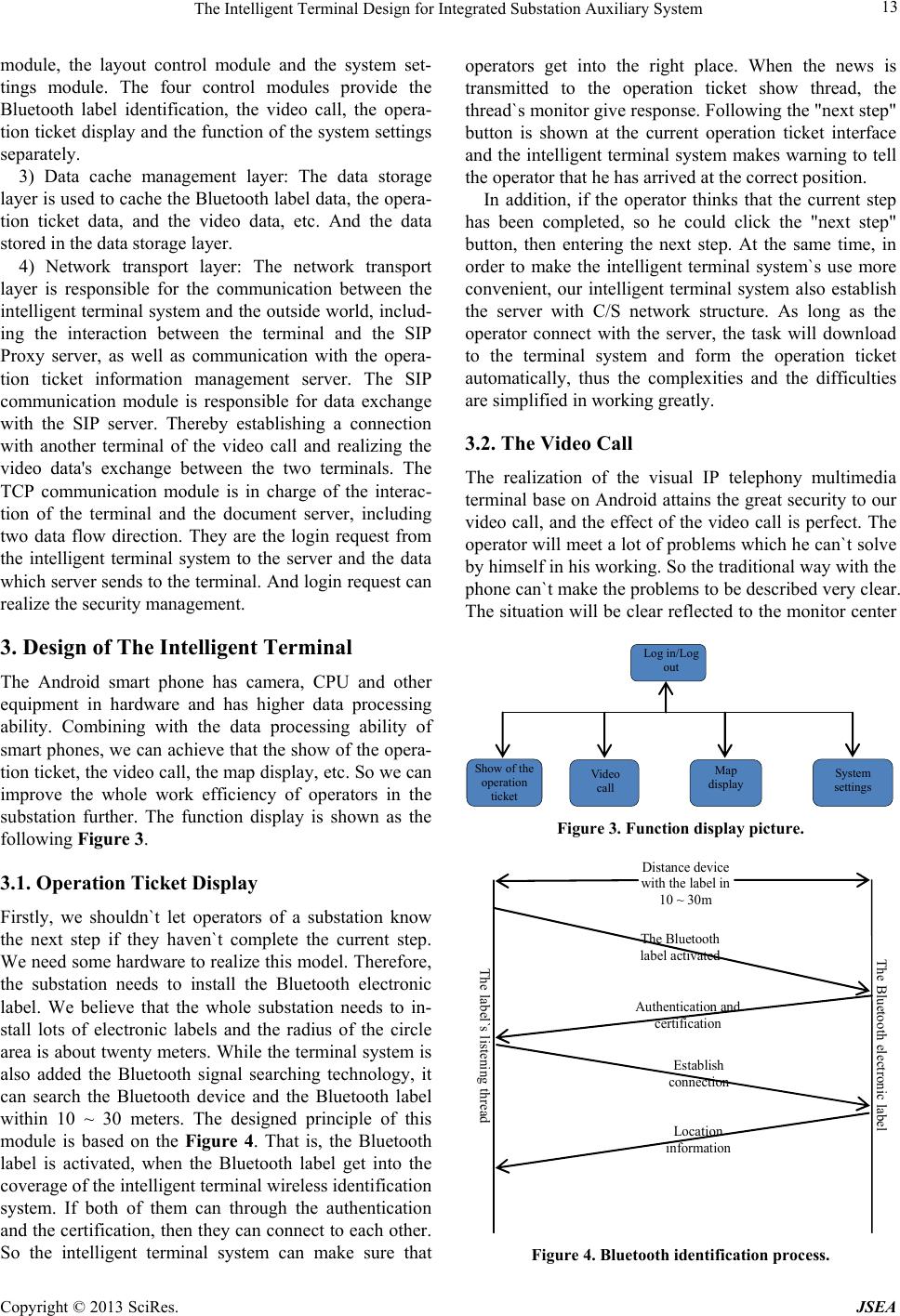 The Intelligent Terminal Design for Integrated Substation Auxiliary System 13 module, the layout control module and the system set- tings module. The four control modules provide the Bluetooth label identification, the video call, the opera- tion ticket display an d the function of the system settings separately. 3) Data cache management layer: The data storage layer is used to cache the Bluetooth label data, the opera- tion ticket data, and the video data, etc. And the data stored in the data storage layer. 4) Network transport layer: The network transport layer is responsible for the communication between the intelligent terminal syste m and the outside world, includ- ing the interaction between the terminal and the SIP Proxy server, as well as communication with the opera- tion ticket information management server. The SIP communication module is responsible for data exchange with the SIP server. Thereby establishing a connection with another terminal of the video call and realizing the video data's exchange between the two terminals. The TCP communication module is in charge of the interac- tion of the terminal and the document server, including two data flow direction. They are the login request from the intelligent terminal system to the server and the data which server sends to th e terminal. And login request can realize the security management. 3. Design of The Intelligent Terminal The Android smart phone has camera, CPU and other equipment in hardware and has higher data processing ability. Combining with the data processing ability of smart phones, we can achieve that the show of the opera- tion ticket, the video call, the map display, etc. So we can improve the whole work efficiency of operators in the substation further. The function display is shown as the following Figure 3. 3.1. Operation Ticket Display Firstly, we shouldn`t let operators of a substation know the next step if they haven`t complete the current step. We need some hard ware to realize this model. Therefore, the substation needs to install the Bluetooth electronic label. We believe that the whole substation needs to in- stall lots of electronic labels and the radius of the circle area is about twenty meters. While the terminal system is also added the Bluetooth signal searching technology, it can search the Bluetooth device and the Bluetooth label within 10 ~ 30 meters. The designed principle of this module is based on the Figure 4. That is, the Bluetooth label is activated, when the Bluetooth label get into the coverage of the intelligent terminal wireless identification system. If both of them can through the authentication and the certification, then they can connect to each other. So the intelligent terminal system can make sure that operators get into the right place. When the news is transmitted to the operation ticket show thread, the thread`s monitor give response. Fo llowing the "n ext step" button is shown at the current operation ticket interface and the intelligent terminal system makes warning to tell the operator that he has arrived at the correct position. In addition, if the operator thinks that the current step has been completed, so he could click the "next step" button, then entering the next step. At the same time, in order to make the intelligent terminal system`s use more convenient, our intelligent terminal system also establish the server with C/S network structure. As long as the operator connect with the server, the task will download to the terminal system and form the operation ticket automatically, thus the complexities and the difficulties are simplified in working greatly. 3.2. The Video Call The realization of the visual IP telephony multimedia terminal base on Android attains th e great security to our video call, and the effect of the video call is perfect. The operator will meet a lot of problems which he can`t so lve by himself in his working. So the traditio nal way with the phone can`t make the problems to be described very clear. The situation will be clear reflected to the monitor center Log i n/Log out Show of the operation ticket Video call Map display System settings Figure 3. Function display pic ture. The Bluetooth electronic label The Bluetoot h label activated Aut hentic ation and certification Establish connection Location information Dis tance devi ce with the label in 10 ~ 30m The label`s listening thread Figure 4. Bluetooth identification process. Copyright © 2013 SciRes. JSEA 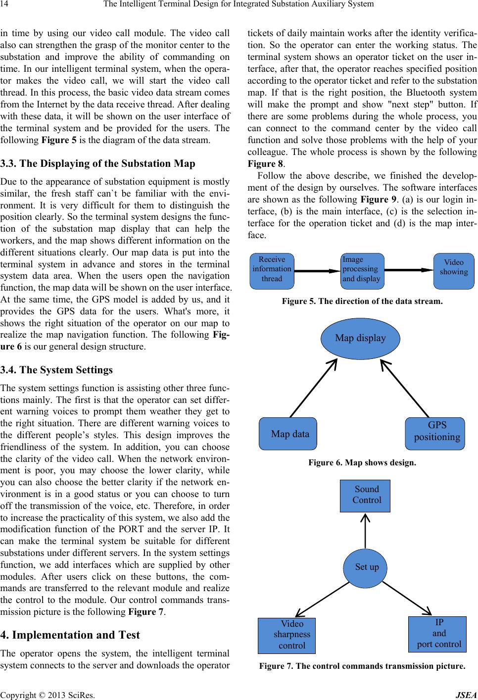 The Intelligent Terminal Design for Integrated Substation Auxiliary System 14 in time by using our video call module. The video call also can strengthen the grasp of the monitor center to the substation and improve the ability of commanding on time. In our intelligent terminal system, when the opera- tor makes the video call, we will start the video call thread. In this process, the basic video data stream comes from the Internet by the data receive thread. After dealing with these data, it will be shown on the user interface of the terminal system and be provided for the users. The following Figure 5 is the diagram of the data stream. 3.3. The Displaying of the Substation Map Due to the appearance of substation equipment is mostly similar, the fresh staff can`t be familiar with the envi- ronment. It is very difficult for them to distinguish the position clearly. So the terminal system design s the func- tion of the substation map display that can help the workers, and the map shows different information on the different situations clearly. Our map data is put into the terminal system in advance and stores in the terminal system data area. When the users open the navigation function, the map data will be shown on the user interface. At the same time, the GPS model is added by us, and it provides the GPS data for the users. What's more, it shows the right situation of the operator on our map to realize the map navigation function. The following Fig- ure 6 is our general desi g n st ructure. 3.4. The System Settings The system settings function is assisting other three func- tions mainly. The first is that the operator can set differ- ent warning voices to prompt them weather they get to the right situation. There are different warning voices to the different people’s styles. This design improves the friendliness of the system. In addition, you can choose the clarity of the video call. When the network environ- ment is poor, you may choose the lower clarity, while you can also choose the better clarity if the network en- vironment is in a good status or you can choose to turn off the transmission of the voice, etc. Therefore, in order to increase the practicality of this system, we also add the modification function of the PORT and the server IP. It can make the terminal system be suitable for different substations under differen t servers. In the system settings function, we add interfaces which are supplied by other modules. After users click on these buttons, the com- mands are transferred to the relevant module and realize the control to the module. Our control commands trans- mission picture is the following Figure 7. 4. Implementation and Test The operator opens the system, the intelligent terminal system connects to the server and downloads the operator tickets of daily maintain works after the identity v erifica- tion. So the operator can enter the working status. The terminal system shows an operator ticket on the user in- terface, after that, the operator reaches specified position according to the operator ticket and refer to the substation map. If that is the right position, the Bluetooth system will make the prompt and show "next step" button. If there are some problems during the whole process, you can connect to the command center by the video call function and solve those problems with the help of your colleague. The whole process is shown by the following Figure 8. Follow the above describe, we finished the develop- ment of the design by ourselves. The software interfaces are shown as the following Figure 9. (a) is our login in- terface, (b) is the main interface, (c) is the selection in- terface for the operation ticket and (d) is the map inter- face. Receive information thread Image processing and display Video showing Figure 5. The direction of the data stream. Map display Map dataGPS positioning Figure 6. Map shows design. Set up Sound Control Video sharpness control IP and port control Figure 7. The control commands transmission picture. Copyright © 2013 SciRes. JSEA 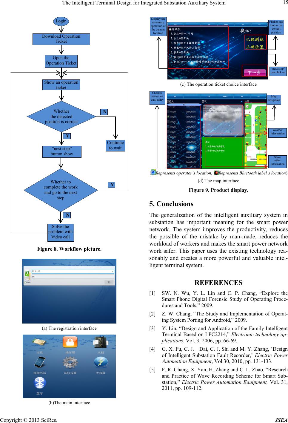 The Intelligent Terminal Design for Integrated Substation Auxiliary System Copyright © 2013 SciRes. JSEA 15 Continue to wait N N Login Download Operation Ticket Open the Operatio n Ti ck et Show an operation ticket Whether the dete cted p os itio n is co rr ect “nest step” button show Whether to complete the work and go to the next step Solve the p roblem with Video call Y Y Display the necessary operati o n of the current location Flicker and hint to the correct position “next stop” ca n click on (c) The operation ticket choice interface Checked person on duty toda yMap navigation Weather Information Show other information (Represents operator`s location, Represent s Bluetooth label`s loc ation) (d) The map interface Figure 9. Product display. 5. Conclusions The generalization of the intelligent auxiliary system in substation has important meaning for the smart power network. The system improves the productivity, reduces the possible of the mistake by man-made, reduces the workload of workers and makes the smart power network work safer. This paper uses the existing technology rea- sonably and creates a more powerful and valuable intel- ligent terminal system. Figure 8. Workflow picture. REFERENCES [1] SW. N. Wu, Y. L. Lin and C. P. Chang, “Explore the Smart Phone Digital Forensic Study of Operating Proce- dures and Tools,” 2009. [2] Z. W. Chang, “The Study and Implementation of Operat- ing System Porting for Android,” 2009. [3] Y. Lin, “Design and Application of the Family Intelligent Terminal Based on LPC2214,” Electronic technology ap- plications, Vol. 3, 2006, pp. 66-69. (a) The registration interface [4] G. X. Fu, C. J. Dai, C. J. Shi and M. Y. Zhang, ‘Design of Intelligent Substation Fault Recorder,’ Electric Power Automation Equipment, Vol.30, 2010, pp. 131-133. [5] F. R. Chang, X. Yan, H. Zhang and C. L. Zhao, “Research and Practice of Wave Recording Scheme for Smart Sub- station,” Electric Power Automation Equipment, Vol. 31, 2011, pp. 109-112. (b)The main interface |