Engineering, 2013, 5, 43-50
http://dx.doi.org/10.4236/eng.2013.59B008 Published Online September 2013 (http://www.scirp.org/journal/eng)
Copyright © 2013 SciRes. ENG
PI-MPC Frequency Con trol of Power System in th e
Presence of DFIG Win d Turbines
Michael Z. Bernard 1, T. H. Mohamed2, Raheel Ali1, Yasunori Mitani1, Yaser Soliman Qudaih1
1Department of Electrical Engineering and Electronics, Kyushu Institute of Technology, Fukuoka, Japan
2Faculty of Energy Eng., Aswan University, Aswan, Egypt
Email: mzbe rna rd@yahoo.com, tarekhie@yahoo.com, raheel.ali@hotmail.co.jp,
mitani@ele.kyutech.ac.jp, yaser_qudaih@yahoo.com
Received July 2013
Abstract
For the recent expansion of renewable energy applications, Wind Energy System (WES) is receiving much interest all
over the world. However, area load change and abnormal conditions lead to mismatches in frequency and scheduled
power interchanges between areas. These mismatches have to be corrected by the LFC system. This paper, therefore,
proposes a new robust frequency control technique involving the combination of conventional Proportional-Integral (PI)
and Model Predictive Control (MPC) controllers in the presence of wind turbines (WT) . The PI-MPC technique has
been designed such that the effect of the uncertainty due to governor and turbine parameters variation and load distur-
bance is reduced. A frequency response dynamic model of a single-area power system with an aggregated generator
unit is introduced, and physical constraints of the governors and turbines are considered. The proposed technique is
tested on the single-area power system, for enhancement of the network frequency quality. The validity of the proposed
method is evaluated by computer simulation analyses using Matlab Simulink. The results show that, with the proposed
PI-MPC combination technique, the overall closed loop system performance demonstrated robustness regardless of the
presence of uncertainties due to variations of the parameters of governors and turbines, and loads disturbances. A per-
formance comparison between the proposed control scheme, the classical PI control scheme and the MPC is carried out
confirming the superiority of the proposed technique in presence of doubly fed induction generator (DFIG) WT.
Keywords: Doubly Fed Induct ion Generat o r; Power Syste m; Model Predictive Control); Proportional Integral
Controller; DFIG Wind Turbi ne; Wind Energ y System (WES)
1. Introduction
Two balances corresponding to two equilibrium points
namely frequency and voltage must be maintained be-
tween generation and utilization in an electric power
system. This enables generation and distribution of qual-
ity electrical power to factories and homes. Breaking or
resetting either of the two balances to a new level will
constitute floating of the equilibrium points. When either
of the two balances is broken and reset at a new level, the
equilibrium points will float. A good-quality electric
power system requires both the frequency and voltage to
remain at standard values during operation.
Thus a control system is important to mitigate the ef-
fects of the random load changes and keep the frequency
and voltage at the standard values. Although active and
reactive power affects the frequency and voltage respec-
tively, the frequency is highly dependent on the active
power while the voltage is highly dependent on the reac-
tive power. Thus the control issue in power systems can
be decoupled into two independent problems. One is
about the active power and frequency control while the
other is about the reactive power and voltage control.
The active power and frequency control is referred to as
load frequency control (LFC) [1] which is the major
concern of this paper.
LFC objectives, which determine the LF C synthesis as
a multi-objective optimization problem [2,3] are con-
cerned with, frequency regulation and tracking the load
demands, maintaining the tie-line power interchanges to
specified values in the presence of modeling uncertain-
ties, system nonlinearities and area load disturbances.
Hence, Frequency control or Load frequency control is
an important function of power system operation where
the main objective is to regulate the output power of each
generator at prescribed levels while keeping the fre-
quency fl uc tuations w i thin pre-specified limits [4].
On the other hand, energy problems and environmen-
tal issues have led to, with recent expansion of renewable
energies, power systems. WES is the fastest growing and
mostly utilized of all the renewable energies and its
M. Z. BERNARD ET AL.
Copyright © 2013 SciRes. ENG
44
global produc tion is pr edicte d to gr ow to 300GW in 2015
[5]. Hence, WES connected to the power systems has
created serious interest and concern among researchers.
In several research works, for example, in [2] it was
pointed out that the renewable integration impacts are
non-zero and can become more significant at higher size
of penetrations.
Variable speed wind turbines (VSWTs) are the most
utilized type of modern WTs. They are partially or totally
decoupled from the power network due to the power
electronic converters which limits their capacity to pro-
vide primary frequ ency support to the network in case of
disturbances. The inertial response of WTs is discussed
in details as in [ 6,7]. A detailed background of frequency
responses, including primary and secondary responses
provided in [6] where detailed comparison between
fixed-speed wind turbines (FSWTs) and doubly fed in-
duction generator (DFIG) type WTs is shown through
detailed simulations, showing that FSWTs and DFIG-
based WTs can contribute to frequency response. In [7],
it is reported that full converter (FC) type WTs are com-
pletely decoupled from the power grid and no contribu-
tion is given to the frequency regulation but pointed out
that DFIG-type WTs have some small contribution to the
power network. In the work, it is assumed that the
VSWTs have negligible inertial response and that addi-
tional control loop is necessary for a proper machine in-
ertial response.
Control system designers today are applying different
control algorithms in order to find the best controller
parameters for optimum solutions. While some of these
methods are very successful for special cases but unsuc-
cessful for other general applications, many control
strategies have been proposed and investigated by several
researchers for LFC design of power systems [8-11].
Robust adaptive control schemes have been developed in
[3,12-16] to deal with changes in system parameters.
Fuzzy logic controllers have been used in many reports
for LFC design in a two area power system [17], with
and without nonlinearities. The applications of artificial
neural network, genetic algorithms, and optimal control
to LFC have been reported in [18,19]. In their findings, it
is observed that the transient response is oscillatory and it
seems that some other elegant techniques are needed to
achieve a desirable performance.
Fixed parameters controllers, such as PI controllers,
are also widely employed in the LFC application. Fixed
parameters controllers are designed at nominal operating
points and may no longer be suitable in all operating
conditions. For this reason, adaptive gain scheduling ap-
proaches have been proposed for LFC synthesis [12,13].
This method overcomes the disadvantages of the conven-
tional PI controllers, which needs adaptation of controller
parameters, but actually, it faces some difficulties, like
the instability of transient response as a result of abrupt
changes in the system parameters in addition to the im-
possibility of obtaining accurate linear time invariant
models at variable operating points [12]. In [20-23], fast
response and robustness against parameter uncertainties
and load changes can be obtained using MPC controller
for single area load frequency control application, but
without WT participation. However, in [24] a new load
frequency control (LFC) using the model predictive con-
trol (MPC) technique in the presence of wind turbines
(WT) was presented and the results demonstrated that the
closed-loop system with MPC controller is robust against
the parameter perturbation of the system and has more
desirable performance in comparison with classical
integral control design in all of the tested scenarios. Also,
it was denoted that wind turbine has a positive effect on
the total response of the system.
Though several optimal and robust control strategies
have been developed for LFC, they all required sug-
gested replacement of the traditionally integral or PI con-
troller with a new robust control scheme. But instead of
replacing the conventional controller with a robust con-
trol scheme, this paper proposes a new robust control
technique involving the combination of a conventional PI
controller and a robust controller, precisely, the MPC, to
form a single controller known as the PI-MPC technique
for power system frequency control. This technique is
more economical, so that, a single PI-MPC scheme will
produce a stronger control signal to control the entire
area rather than using multiple controllers nor removing
or replacing traditional controllers already in the system.
This works since the MPC adapts well to different phys-
ical setups and allows for a unified approach [22-24]
while PI controller can have zero steady state error
though its disadvantage has to do with maximum over-
shoot and high settling time plus inability to adapt to
different changes in system parameters [22]. The respec-
tive PI and MPC controllers may not be new but the
combination of these two control schemes to form a single
controller is completely new in power system research.
In this paper, the load frequency control for a single
area power system in the presence of WES has been de-
veloped based on the PI-MPC technique. Each local area
includes an aggregated wind turbine model (which con-
sists of 200 wind turbine units) beside the main genera-
tion unit. With the PI-MPC technique, the MPC produces
its optimal output derived from a quadratic cost function
minimization based on the dynamic model of the single
area power system which combines with the PI signal.
The technique calculates the optimal control signal while
respecting the given constrains over the output frequency
deviation and the load change. The effects of the physical
constraints such as generation rate constraint (GRC) and
speed governor dead band are considered [20]. The power
M. Z. BERNARD ET AL.
Copyright © 2013 SciRes. ENG
45
system with the proposed PI-MPC technique has been
tested through the effect of uncertainties due to go vernor
and turbine parameters variation and load disturbance
using computer simulation. A comparison has been made
between the proposed PI-MPC controller, the traditional
PI controller and MPC, confirming the superiority of the
proposed technique. The simulation results proved that
the proposed controller can be applied successfully to the
application of power system frequency control including
that with WT. The rest of the paper is organized as fol-
lows: General overview of MPC and its cost function are
presented in Section 2. In Section 3, the simplified wind
turbine model, the description of the dynamics of the
power system and the overall structure of the implemen-
tation scheme as a single area power system together
with the PI-MPC technique are explained. Simulation
results and general remarks are presented in Section 4.
Finally, the paper is concluded in Section 4.
2. General Overvi e wmpc
The MPC has proved an efficient control in a wide range
of applications in industry such as chemical process, pe-
trol industry, electromechanical systems and many other
applications. Figure 1 below illustrates a Simple struc-
ture of MPC controller.
The MPC scheme uses a prediction model of the sys-
tem response to obtain the control actions by minimizing
an objective function. The objective of the optimization
is to minimize the difference between the predicted and
reference response, and the control effort subjected to
prescribed constraints.
The effectiveness of MPC is equivalent to optimal
control. At each control interval, the first input in the
optimal sequence is sent into the plant, and the entire
calculation is repeated at subsequent control intervals.
The purpose of taking new measurements at each time
step is to compensate for unmeasured disturbances and
model inaccuracy, both of which cause the system output
to be different from the one predicted by the model
[14,15].
Figure 1. Simple structure of MP C.
An internal model is used to predict the future plant
outputs based on the past and current values of the inputs
and outputs and on the proposed optimal future control
actions. The prediction has two main components: the
free response which being expected behavior of the out-
put assuming zero future control actions, and the forced
response which being the additional component of the
output response due to the candidate set of future con-
trols. For a linear system, the total prediction can be cal-
culated by summing both of free and forced responses.
The reference trajectory signal is the target values the
output should attain. The optimization is subject to con-
straints on both manipulated and controlled variables
[22]. The general object is to tighten the future output
error to zero, with minimum input effort. Therefore, the
optimizer calculates the best set of future control action
by minimizing a cost function (J) which is generally a
weighted sum of square predicted errors and square fu-
ture control values, e.g. in the Generalized Predictive
Control (GPC):
( )
( )()()
( )()
2
1
2
123
2
1
ˆ
J[/ ]
[ 1]
u
N
jN
N
j
NNNjykjk kj
j ukj
βω
λ
=
=
=+ −+
+ +−
(1)
where N1 and N2 are the lower and upper prediction
horizons over the output, Nu is the control horizon,
( )
βj
,
( )
λj
are weighting factors. The control horizon
permits to decrease the number of calculated future con-
trol according to the relation:
( )
0uK j∆ +=
for u
jN
and
( )
Kj
ω
+
repre-
sents the reference trajectory over the future horizon .
Constraints over the control signal, the outputs and the
control signal changing can be added to the cost function
as follows :
min max
uuk u
( )
min max
uuk u∆ ≤∆≤∆
min k max
y yy≤≤
Details of MPC are discussed in [22-24].
3. System Configuration
3.1. System Dynamics
In this section, a simplified frequency response mode l for
a single area power system with an aggregated generator
unit is described [2].
The overall generator-load dynamic relationship be-
tween the incremental mismatch power
mL
PP∆ −∆
and
the frequency devia t ion
f
can be expressed as:
11
.222
mL
D
sfPP f
HHH
 
∆=⋅∆− ⋅∆− ⋅∆
 
 
(2)
M. Z. BERNARD ET AL.
Copyright © 2013 SciRes. ENG
46
While the dynamics of the governor can be expressed
as:
11
m gm
tt
sPP P
TT
 
⋅∆=⋅∆−⋅∆
 
 
(3)
and the dynamics of the turbine can be expressed as:
1 11
.
gc g
g gg
sPPf P
TRT T
 
⋅∆=⋅∆−⋅∆ −⋅∆
 
 
 
(6)
The block diagrams of the past equations are included
in Figure 2 where:
:
g
P
Change in the governor out put
:
m
P Change in mechanical power
:f
Frequency deviation
:
L
P
The load change
:
c
P
Supplementary control action
:H
Equivalent inertial constant
:D
Equiva l e nt damping coefficient
:R
Speed drop characteristics
and :
gt
TT
are governor and turbine time constant re-
spectively.
3.2. Simplified Wind Turbine Model for
Frequency Studies
Figu re 3 above shows a simplified model of DFIG based
wind turbine (WT) for frequency response [24]. This
simplified model can be described by the following equ-
ations:
2qr
11
X
1iV
T
qr qr
si T

=−⋅+⋅


(5)
Figure 2. The block diagram of a single area power system
Figure 3. Simplified model of DFIG based wind turbine [19].
32
.22
qr m
tt
XX
s iT
HH
ω
 
=− ⋅+⋅
 
 
(6)
3e qr
P Xi
ω
=⋅⋅
(7)
For linearization, Equation (14) can be rewritten as:
3e optqr
P Xi
ω
= ⋅⋅
(8)
where
opt
ω
is the operating point of the rotational speed,
s
is the differential operator,
e
T
is the electromagnetic
torque,
m
T
is the mechanical power change,
ω
is the
rotational speed, e
P is the active power of wind turbine,
qr
i
is q-axis component of the rotor current,
qr
V
is
q-axis component of the rotor voltage and
t
H
is the
equivalent inertia constant of wind turbine. Table 1
shows the detailed expressions of the main parameters
utilized for the simplified model of Figure 3.
Where:
2
0m
rr ss
L
LL L
= +
sss m
L LL= +
rrrs m
LLL= +
s
ω
is synchronous speed, m
Lis the magnetizing induc-
tance,
r
R
and
s
R
are the respective rotor and stator
resistances,
r
L
and
s
L
are the rotor and stator leakage
inductances respectively, while rr
L and ss
L are the
rotor and stator self-inductances respectively.
4. Overall System Structure
The block diagram of a simplified frequency response
model for a single area power system with aggregated
unit including the proposed PI-MPC controller is shown
in Figure 4.
The system consists of the rotating mass and load,
nonlinear turbine with GRC, and governor with dead-
band constraint [1].
The frequency deviation is used as feedback for the
closed loop control system. Initially, a PI controller in the
system receives the frequency signal ∆f , to be controlled,
and hence produces the supplementary action
Δ
c
P
. Then,
in an effort to improve system performance, the meas-
ured and reference frequency deviation
ref
f
(where
0)
ref
f Hz∆=
and the reference wind rotational speed,
ref
ω
, where,
( )
ref opt
ωω
=
are fed to the MPC controller
in order to obtain the supplementary control action
c
P
.
This control action
c
P
, is then added to
Table 1. Parameters for Fi gure 3 [24].
X2 X3 T1
1
T
R
m
ss
L
L
0
ss
L
R
ω
M. Z. BERNARD ET AL.
Copyright © 2013 SciRes. ENG
47
c
ΔP
. The resulting signal of the PI-MPC which is simply
the combination of the signals due to the PI and MPC
controllers respectively:
c cc
ˆ
PPP∆=∆ +∆
is fed to the
governor, giving the governor valve position which sup-
plies the turbine to give the mechanical power change
m
P
. Both the active power change of wind turbine
e
P
and the load change
L
P
affect the mechanical
power change giving the input of the rotating mass and
load bloc k to provide ac tual frequency deviation
f
.
5. Results and Discussion
In order to validate the effectiveness of the proposed
scheme Computer simulations have been carried out in
the Matlab/Simulink environment. A practical single area
power system has the following nominal parameters [2]
listed below in Table 2.
Simulation studies are carried out for the proposed
controller with generation rate constraint (GRC) of 10%
p.u. per minute. The maximum value of dead band for
governor is specified as 0.05%. The parameters of the
MPC controller are set as follows:
Prediction horizon = 10, Control hor izon = 2, Weights
on manipulated variables = 0, Weights on manipulated
variable rates = 0.1, Weights on the output signals = 1
and Sampling interval = 0.0003 sec. Constraints are im-
posed over the control action, and frequency deviation.
They are considered as follows:
Max. control action = 0.25 pu, Min. control action =
0.25 pu,
Max. frequency deviation = 0.25 pu, and Min. fre-
quency de vi a tion = 0.25 pu.
The wind turbine field consists of 200 units of 2MW
rated variable speed wind turbine VSWTs, the wind tur-
bine parameters and operating point are indicated in Ta-
ble 3.
Figure 4. The block diagram of a single area power system
including the proposed P I -MPC controller
Table 2. Parameters and data of a practical single area
power system.
D (p.u/Hz) H (pu.sec) R (Hz/p.u)
(sec)
(sec)
0.015 0.08335 3.00 0.08 0.4
Table 3. Wind turbine parameter s an d op erating point [25].
Operating
point (mw) Wind
speed (m/s ) Rotational
speed (m/s )
247 11 1.17
(pu)
(pu)
X
(pu)
0.00552 0.00491 0.1
X
(pu)
X
(pu)
(pu)
0.09273 3.9654 4.5
m
X
is the magnetizing reactance wh ile lr
X and
ls
X
are the leakage reactance of the rotor and stator respec-
tively.
For the simulations studies, three cases are investi-
gated. The first case is a nominal case where the power
system operates under normal operating conditions. The
second case the changed case where changes are made in
the parameters of the power system so as to carry out
robustness investigations and comparison is made be-
tween the controllers. In the third case, the effect of WT
on the power system frequency is investigated consider-
ing variable wind speed. The parameters of the PI con-
troller are K( p) = 0.37 and K(s) = 0.745.
5.1. First Case:System Performance at Nominal
Case
The system performance with the proposed PI-MPC con-
troller during WT participation at nominal parameters is
tested and comparison is made between the system per-
formances with conventional proportional integrator K(p)
= 0.37 and
( )
Ks0.745 / s= − in the presence of a step
load change
L
P0.02 p.u.∆=
at
t30 sec.=
Figure 5
shows the simulation results of the proposed PI-MPC,
MPC and only conven tional PI sys tems. The resu lts from
the top to the bottom are: the mechanical power change,
m
P
, in per unit, the frequency deviations,
f
, in Hertz
and the governor’s controlled input signals,
s
P
, in per
unit. It can be seen that after a step load changed is expe-
rienced by the system at t = 30 sec, the conventional
integral controller gradually brings the system back to its
reference point but took a much longer time. With the
proposed PI-MPC controller, the system is more stable
and faster as compared to the system with MPC only or
conventional PI controller only.
5.2. Second Case: Robustness Evaluat ion
To evaluate the robustness of the proposed PI-MPC
technique, changes are made in the parameters of the
power system by increasing the governor and turbine
time constants to
g
T0.12sec=
and t
T0.95 sec=, re-
spectively.
M. Z. BERNARD ET AL.
Copyright © 2013 SciRes. ENG
48
Figure 5. Power system response to a small load change a)
Mechanical power change, b) frequency deviation and c)
governor’s control signal.
Figure 6 depicts the system response with the respec-
tive PI, MPC and PI-MPC control schemes during this
case of study. The load change is assumed to be as de-
scribed in the first case. It has been shown that, with the
traditional controller , the system becomes unstab le while
with MPC controller, the system response is more en-
hanced. However, it can be seen that the PI-MPC is
much faster in damping the power system oscillations
and hence yields the most desirable result in enhance-
ment of the system frequency by displaying robust cha-
racteristics in the presence of load change and p arameters
uncertainties.
5.3. Third Case: Variable Wind Speed
In order to further test the effectiveness of the proposed
PI-MPC control technique. Figure 7 shows the variable
wind speed pattern in the presence of which the simula-
tion was performed. It can be seen that the wind speed
initially 12.5 m/s fluctuates between 10 m/s to 15 m/s.
The simulation was performed in the presence of variable
wind speed and the system is observed. From Figure 8, it
Figure 6. Power system response to different changes: (a)
Mechanical power change, (b) frequency deviation and (c)
governor’s control signal.
Figure 7. Simulated wind speed.
is observed that with the proposed strategy, the system is
stable which verifies the effectiveness of the proposed
control strategy. Also, the figure indicates that even
though the wind speed changes, the presence of wind
turbine lead to enhancement the system performance
with the propose P I -MPC controller, significantly.
6. Conclusion
This paper investigates robust frequency control of a
28 30 32 343638 40 424446 4850
0
0.005
0.01
0.015
0.02
0.025
0.03
0.035
time (sec)
(a)
P
m
(p u)
Mechanical Pow er Change
Step Load Change
PI
MPC
PI-MPC
28 30 32 34 36 38 40 42 44 46 48 50
-0.1
-0.05
0
0.05
ti me(sec)
(b)
f (Hz)
Frequency Deviat ion
PI
MPC
PI-MPC
28 30 32 34 36 38 40 42 44 4648 50
0
0.01
0.02
0.03
0.04
0.05
time (sec)
(c)
P
C
(p u)
Govern or Cont r ol Sign al
PI
MPC
PI-MPC
28 3032 3436 3840 42 4446 48 50
-0.02
0
0. 02
0. 04
Mechanical Pow er Ch ange
time (sec)
(a)
P
m
(p u)
PI
MPC
PI-MPC
28 3032 34 363840 42 444648 50
-0.2
-0.1
0
0. 1
0.2 Frequency Dev iat ion
time(sec)
(b)
f (Hz)
PI
MPC
MPC
28 3032 34 3638 40 42 44 46 4850
-0.1
-0.05
0
0. 05
0. 1
0. 15
Govern or Cont r ol Sign al Change Case
time (sec)
(c)
P
C
(p u)
PI
MPC
PI-MPC
05101520 25 3035 40 45 50
10
10.5
11
11.5
12
12.5
13
13.5
14
14.5
15
time (s)
Wind Speed ( m / s)
WIND SPEED(m/s)
WIND SPEED(m/s)
M. Z. BERNARD ET AL.
Copyright © 2013 SciRes. ENG
49
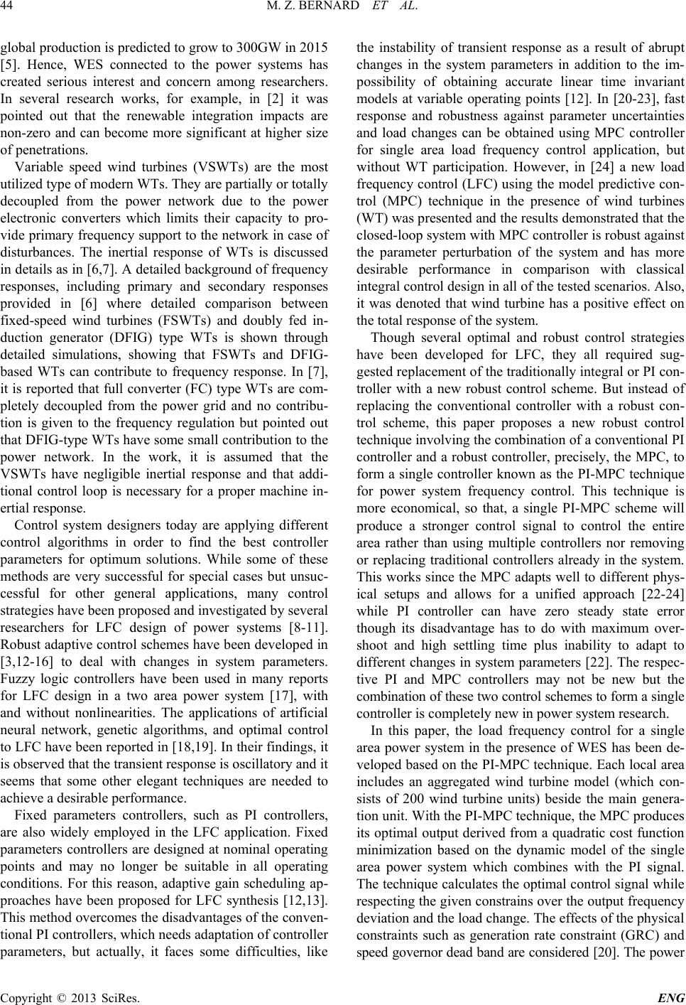
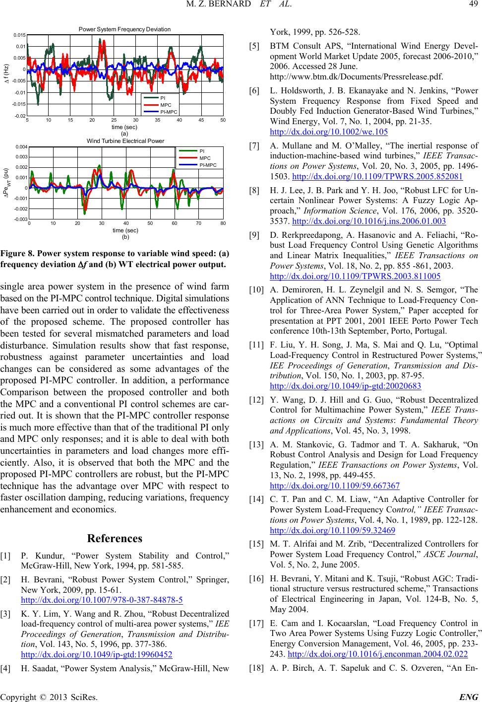
Figure 8. Power system response to variable wind speed: (a)
frequency deviation f and (b) WT electrical power output.
single area power system in the presence of wind farm
based on the P I-M PC control technique. Digital simulations
have been carried out in order to validate the effectiveness
of the proposed scheme. The proposed controller has
been tested for several mismatched parameters and load
disturbance. Simulation results show that fast response,
robustness against parameter uncertainties and load
changes can be considered as some advantages of the
proposed PI-MPC controller. In addition, a performance
Comparison between the proposed controller and both
the MPC and a conventional PI control schemes are car-
ried out. It is shown that the PI-MPC controller response
is much more effective than that of the traditional PI only
and MPC only respon ses; and it is able to deal with both
uncertainties in parameters and load changes more effi-
ciently. Also, it is observed that both the MPC and the
proposed PI-MPC controllers are ro bust, but the PI-MPC
technique has the advantage over MPC with respect to
faster oscillation damping, reducing variations, frequency
enhancement and economics.
References
[1] P. Kundur, Power System Stability and Control,”
McGraw-Hill, New York, 1994, pp. 581-585.
[2] H. Bevrani, Robust Power System Control,” Springer,
New York, 2009, pp. 15-61.
http://dx.doi.org/10.1007/978-0-387-84878-5
[3] K. Y. Lim, Y. Wang and R. Zhou, “Robust Decentralized
load-frequency control of multi-area powe r systems,” IEE
Proceedings of Generation, Transmission and Distribu-
tion, Vol. 143, No. 5, 1996, pp. 377-386.
http://dx.doi.org/10.1049/ip-gtd:19960452
[4] H. Saadat, Powe r System Analysis,McGraw-Hill, New
York, 1999, pp. 526-528.
[5] BTM Consult APS, “International Wind Energy Devel-
opment World Market Update 2005, forecast 2006-2010,”
2006. Accessed 28 June.
http://www.btm.dk/Documents/Pressrelease.pdf.
[6] L. Holdsworth, J. B. Ekanayake and N. Jenkins, “Power
System Frequency Response from Fixed Speed and
Doubly Fed Induction Generator-Based Wind Turbines,
Wind Energy, Vol. 7, No. 1, 2004, pp. 21-35.
http://dx.doi.org/10.1002/we.105
[7] A. Mullane and M. O’Malley, “The inertial response of
induction-machine -based wind turbines,” IEEE Transac-
tions on Power Systems, Vol. 20, No. 3, 2005, pp. 1496-
1503. http://dx.doi.org/10.1109/TPWRS.2005.852081
[8] H. J. Lee, J. B. Park and Y. H. Joo, “Robust LFC for Un-
certain Nonlinear Power Systems: A Fuzzy Logic Ap-
proach,Information Science, Vol. 176, 2006, pp. 3520-
3537. http://dx.doi.org/10.1016/j.ins.2006.01.003
[9] D. Rerkpreedapong, A. Hasanovic and A. Feliachi, “Ro-
bust Load Frequency Control Using Genetic Algorithms
and Linear Matrix Inequalities,” IEEE Transactions on
Power Systems, Vol. 18, No. 2, pp. 855 -861, 2003.
http://dx.doi.org/10.1109/TPWRS.2003.811005
[10] A. Demiroren, H. L. Zeyne l gi l and N. S. Semgor, “The
Application of ANN Technique to Load-Frequency Con-
trol for Three-Area Power System,” Paper accepted for
presentation at PPT 2001, 2001 IEEE Porto Power Tech
conference 10th-13th September, Porto, Portugal.
[11] F. Liu, Y. H. Song, J. Ma, S. Mai and Q. Lu, Optimal
Load-Frequency Control in Restructured Power Systems,”
IEE Proceedings of Generati on, Transmission and Dis-
tribution, Vol. 150, No. 1, 2003, pp. 87-95.
http://dx.doi.org/10.1049/ip-gtd:20020683
[12] Y. Wang, D. J. Hill and G. Guo, “Robust Decentralized
Control for Multimachine Power System,” IEEE Trans-
actions on Circuits and Sy stems: Fundamental Theory
and Applications, Vol. 45, No. 3, 1998.
[13] A. M. Stankovic, G. Tadmor and T. A. Sakharuk, “On
Robust Control Analysis and Design for Load Frequency
Regulation,” IEEE Transactions on Power Systems, Vol.
13, No. 2, 1998, pp. 449-455.
http://dx.doi.org/10.1109/59.667367
[14] C. T. Pan and C. M. Liaw, “An Adaptive Controller for
Power System Load-Frequency Control,” IEEE Transac-
tions on Power Systems, Vol. 4, No. 1, 1989, pp. 122-128.
http://dx.doi.org/10.1109/59.32469
[15] M. T. Alrifai and M. Zr ib,Decentralized Controllers for
Power System Load Frequency Control,ASCE Journal,
Vol. 5, No. 2, June 2005.
[16] H. Bevrani, Y. Mitani and K. Tsuji, “Robust AGC: Tradi-
tional structure versus restructured scheme,” Transactions
of Electrical Engineering in Japan, Vol. 124-B, No. 5,
May 2004.
[17] E. Cam and I. Kocaarslan, “Load Frequency Control in
Two Area Power Systems Using Fuzzy Logic Controller,
Energy Conversion Management, Vol . 46, 2005, pp. 233-
243. http://dx.doi.org/10.1016/j.enconman.2004.02.022
[18] A. P. Birch, A. T. Sapeluk and C. S. Ozveren, “An En-
510152025303540 45 50
-0.02
-0.015
-0.01
-0.005
0
0.005
0.01
0.015 Power System Frequency Dev iat ion
time (sec)
(a)
f (Hz)
PI
MPC
PI-MPC
010 20 30 40 50 60 70 80
-0.003
-0.002
-0.001
0
0.001
0.002
0.003
0.004
time (sec)
(b)
Pe
WT
(p u)
Win d Tur bine El ect r ical Pow er
PI
MPC
PI-MPC
M. Z. BERNARD ET AL.
Copyright © 2013 SciRes. ENG
50
hanced Neural Network Load Frequency Control Tech-
nique,” Conference Publication No. 389, International
Conference on Control, Coventry, UK, 21-24 March
1994, pp. 409-415.
[19] Y. L. Abdel-Magid and M. M. Dawoud, “Genetic Algo-
rithms Applications in Load Frequency Control,” Genetic
Algorithms in Engineering Systems: Innovations and Ap-
plications, Conference Publications No. 414, IEE, 12-14
September 1995, 1995.
[20] J. Thomas, D. Dumur, J. Buisson and H. Gueguen, Model
Predictive Control for Hybrid Systems under a State Par-
tition based MLD Approach (SPMLD),” International
Conference on Informatics in Control, Automation and
Robotics ICINCO’04, Vol. 3, Setúbal, pp. 78-85.
[21] J. Richalet, A. Rault, J. L. Testud and J. Japon, “Model
Predictive Heuristic Control: Application to Industrial
Processes,” Automatica, Vol. 14, No. 5, 1978, pp. 413-
428. http://dx.doi.org/10.1016/0005-1098(78)90001-8
[22] C. W. De Silva, “Mechatronic Systems: Devices, Design,
Control, Operation and Monitoring,” Taylor and Francis
Group, LLC, 2008.
[23] T. H. Mohamed, H. Bevrani, A. A. Hassan and T. Hiya-
ma, “Model Predictive Based Load Frequency Control
Design,” 16th International Conference of Electrical En-
gineering, Busan, Korea, July 2010.
[24] Y. S. Qudaih, M. Bernard, Y. Mitani and T. H. Mohamed,
Model Predictive Based Load Frequency Control Design
in the Presence of DFIG Wind Turbine,Proceeding of
the 2nd International Conference on Electric Power and
Energy Conversion Systems (EPECS’11), Sharjah, UAE,
15-17 Nov. 2011.
[25] J. Morel, H. Bevrani, T. Ishii and T. Hiyama,A Robust
Control Approach for Primary Frequency Regulation
through Variable Speed Wind Turbines,” IEEJ Transac-
tions on Power and Energy, Vol. 130, No. 11, 2010, pp.
1002-1009.