Communications and Network, 2013, 5, 573-577
http://dx.doi.org/10.4236/cn.2013.53B2103 Published Online Septembaer 2013 (http://www.scirp.org/journal/cn)
Copyright © 2013 SciRes. CN
Vehicle Relay Attack Avoidance Methods Using RF Signal
Strength
Gyu-Ho Kim, Kwan-Hyung Lee, Shim-Soo Kim, Ju-Min Kim
Advanced Research Part, Daedong, Seoul, The Republic of Korea
Email: c harran@dae-dong.biz, saicocoisa@hanyang .ac.kr, sskim@dae-dong.biz, jumin1985@dae-dong.biz
Received April 2013
ABSTRACT
The number of passenger cars equipped with a smart key system continues to increase due to the convenience of the
system. A smart key system allows the driver to enter and start a car without using a mechanical key through a wir eless
authentication process between the car and the key fob. Even though a smart key system has its own security scheme, it
is vulnerable to the so-called relay attacks. In a relay attack, attackers with signal relaying devices enter and start a car
by relaying signals from the car to the owner’s fob. In this study, a method to detect a relay attack is proposed. The sig-
nal strength is used to determine whether the signal received is from the fob or the attacker’s relaying devices. Our re-
sults show that relay attacks can be avoided by using the proposed method.
Keywords: Authentication; Relay Attack; Signal Strength; Smart Key System
1. Introduction
Since the introduction of the smart key at the present, the
number of smart key installations has gradually increased
due to the convenience of the device. A smart key system
provides a driver with the ability to enter and start a car
without using a mechanical key through a wireless au-
thentication process. Even though a smart key system has
its own security scheme, it is vulnerable to relay attacks.
Tests on cars with smart key systems indicate that relay
attacks can easily be performed by relaying a low fre-
quency (LF) signal from the car through a relay attack
device to the car’s key fob. Most vehicles are susceptible
to these relay attacks, regardless of the original equip-
ment manufacturer (OEM). In this study, relay attack tests
were performed on nine different cars from seven OEMs
to confirm the potential for these attacks. From the data,
an algorithm was developed to deter unauthorized entry
using a threshold received signal strength indication (RSSI)
value for the RF signal from the key fob.
2. Overview of Smart Key Systems
2.1. Definition
A smart key system is the equipment that allo ws a driver
to enter and start a car through the process of authentica-
tion using fobs registered in the car. Using this system,
the driver can control the door, trunk, and alarm by press-
ing the button on the fob from a distance. Smart key sys-
tems have two main functions, listed below. Smart key
system is the equipment that allows the driver to enter
and start the car through the process of authentication
with fobs registered in the car or allows the driver to
control door, trunk, and alarm by pressing the button on
the fob from a distance. Smart key system has the fol-
lowing two main functions.
2.2. Functions
The passive-entry passive-start (PEPS) feature is one of
the functions of smart key systems that allows the driver
to enter and start the car. If the driver triggers the door
handle, then a LF signal (challenge signal) is transmitted
from the car to the fob. The fob responds to the car (re-
sponse signal) by sending a radio frequency (RF) signal.
The car decodes the RF signal received from the fob and
checks to see whether or not the fob is registered. If the
driver triggers the door handle, then the door locks when
the driver leave s the car . Relay attack pro blems commonly
occur during the PEPS operation.
Remote keyless entry (RKE) is the second function of
smart key systems that allows the driver to control the
car from a distance. If the driver presses the button on the
fob, then the car doors automatically lock or unlock.
2.3. Types of Relay Attacks
A relay attack is divided into LF and RF relay attacks,
depending on which type f signal is relayed through the
G.-H. KIM ET AL.
Copyright © 2013 SciRes. CN
574
relay attack devices. A LF relay attack sends a LF signal
from the car to the fob. A RF relay attack relays both a
LF signal from the car and a RF signal from the fob to
the car. For a RF relay attack, the possible attack distance
is longer (up to 1 km) because a RF signal is also relayed.
In this paper, we concentrated solely on a LF relay attack
(Figures 1 and 2).
2.4. Concept of LF Relay Attack Devices
LF relay attack devices located between the car and
the fob amplify and transfer the LF signal that is sent
when the driver triggers the door handle. Once the fob
receives this LF signal, it verifies the information and
responds to the car. The car receives this signal and
confirms the information and then locks or unlocks
the door.
Relay attack devices are composed of two compo-
nents: RA1 and RA2. RA1 is responsible for receiv-
ing the LF signal from the car and transmitting it to
RA2. RA2 is responsible for receiving the signal from
RA1 and transmitting it to the fob.
A 2.4 GHz module is commonly used to transfer the
signal between RA1 and RA2
2.5. Performance of LF Relay Attack Devices
Relay attack tests were performed on nine different cars
from seven OEMs to confirm the potential for relay at-
tacks in these vehicles. Our results showed that most cars
with smart key systems were vulnerable to relay attacks
(Table 1).
2.6. Relay Attack Test Results
For the test, the LF frequency, supplier and relay at-
tack vulnerability of each OEM were investigated
Both passive entry and/or pas s ive start were possible.
OEM E’s car η had no passive ent ry option.
Figure 1. Concepts of a low frequency (LF) relay attack
Figure 2. Concepts of a radio frequency (RF) relay atta ck.
G.-H. KIM ET AL.
Copyright © 2013 SciRes. CN
575
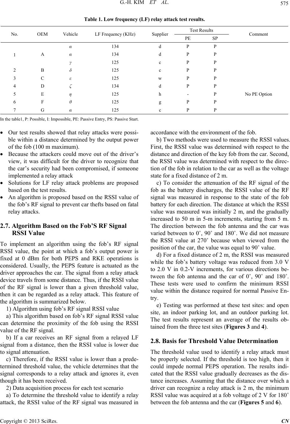
Table 1. Low frequency (LF) relay attack test r es u lts .
No. OEM Vehicle LF Frequency (KHz) Supplier Test Results Comment
PE SP
1 A
α 134 d P P
α 134 d P P
γ 125 c P P
2 B δ 125 c P P
3 C ε 125 w P P
4 D ζ 134 d P P
5 E η 125 h - P No PE Option
6 F θ 125 g P P
7 G α 125 c P P
In the table1, P: Possi bl e, I: Impossible, PE: Passive Entry, PS: Passive Start.
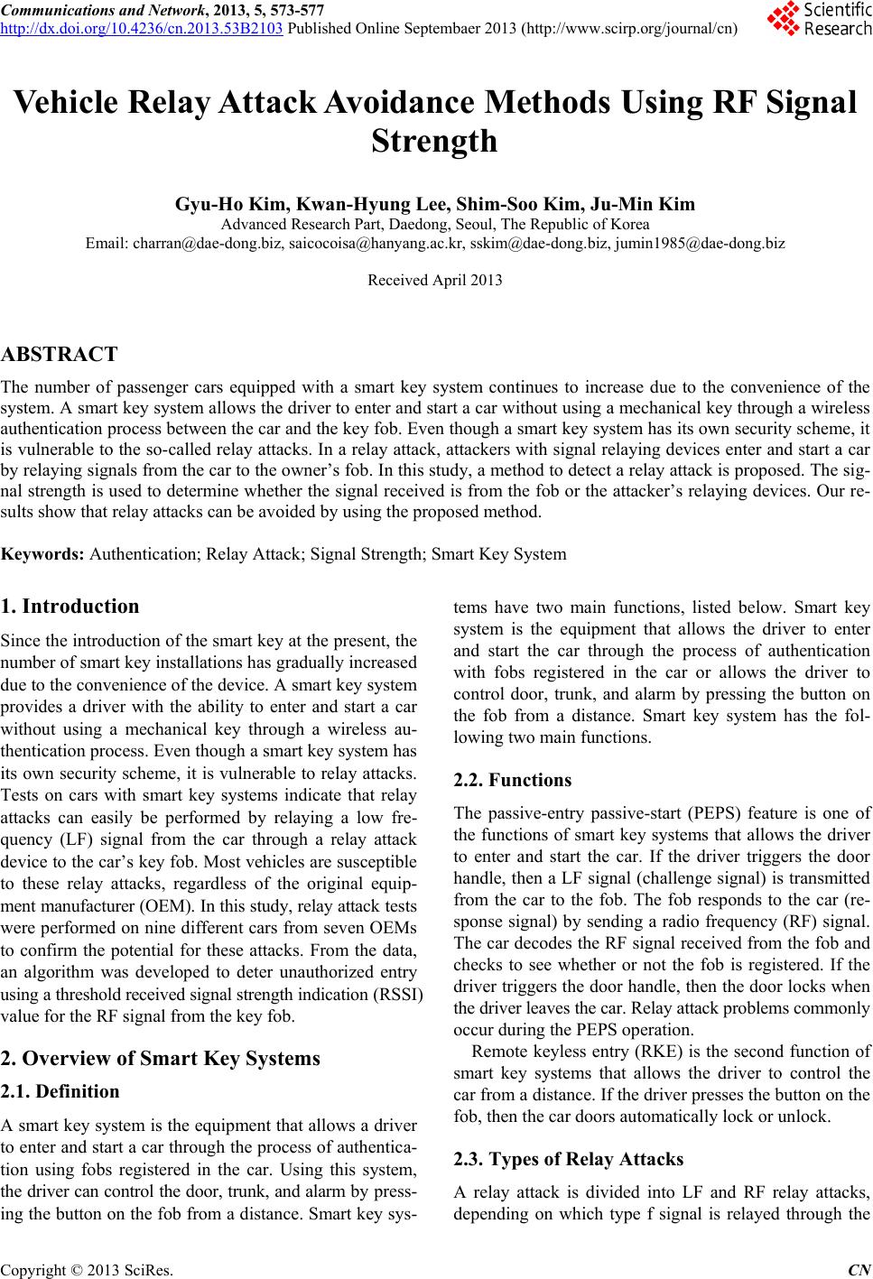
Our test results showed that relay attacks were possi-
ble within a distance determined by the output power
of the fob ( 100 m maximu m) .
Because the attackers could move out of the driver’s
view, it was difficult for the driver to recognize that
the car’s security had been compromised, if someone
implemented a relay attack
Solutions for LF relay attack problems are proposed
based on the test results.
An algorithm is propo sed based on the RSSI value of
the fob’s RF signal to prevent car thefts based on fatal
relay attacks.
2.7. Algorithm Based on the Fob’S RF Signal
RSSI Value
To implement an algorithm using the fob’s RF signal
RSSI value, the point at which a fob’s output power is
fixed at 0 dBm for both PEPS and RKE operations is
considered. Usually, the PEPS feature is actuated as the
driver approaches the car. The signal from a relay attack
device travels from some distance. Thus, if the RSSI value
of the RF signal is lower than a given threshold value,
then it can be regarded as a relay attack. This feature of
the algorithm is summarized below.
1) Algorithm using fob’s RF signal RSSI value
a) This algorithm based on fob’s RF signal RSSI value
can determine the proximity of the fob using the RSSI
value of the RF signal.
b) If a car receives an RF signal from a relayed LF
signal from a distance, then the RSSI value is lower due
to signal attenuation.
c) Therefore, if the RSSI value is lower than a prede-
termined threshold value, the vehicle determines that the
signal corresponds to a relay attack and ignores it, even
though it ha s b e e n re c e i ved.
2) Data acquisition process for each test scenario
a) To determine the threshold value to identify a relay
attack, the RSSI value of the RF signal was measured in
accordance with the environment of the fob.
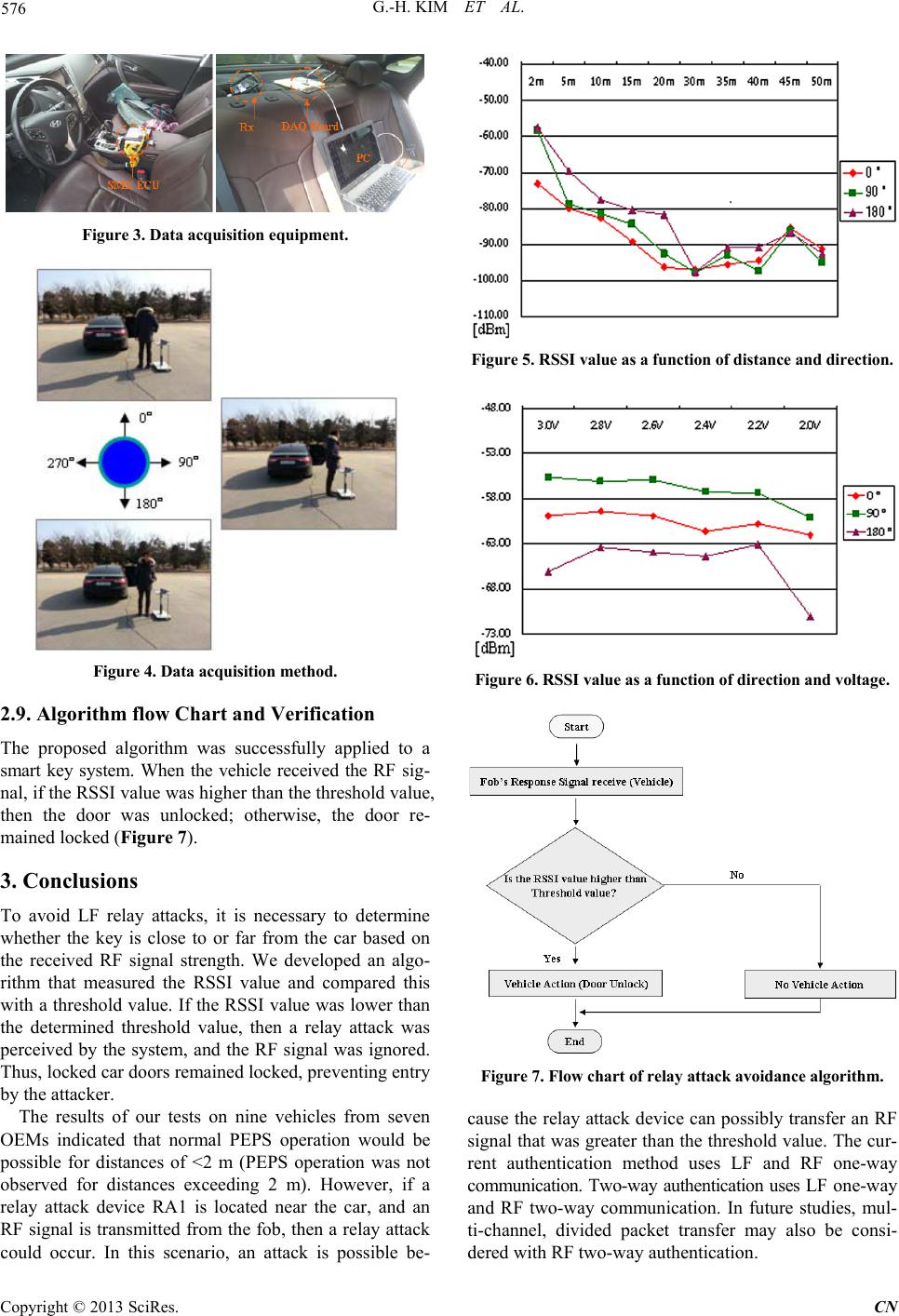
b) Two methods were used to measure the RSSI values.
First, the RSSI value was determined with respect to the
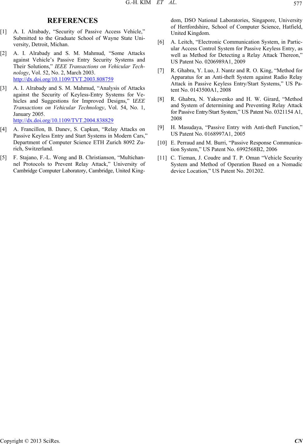
distance and direction of the key fob from the car. Second,
the RSSI value was determined with respect to the direc-
tion of the fob in relation to the car as well as the voltage
state for a fixed distance of 2 m.
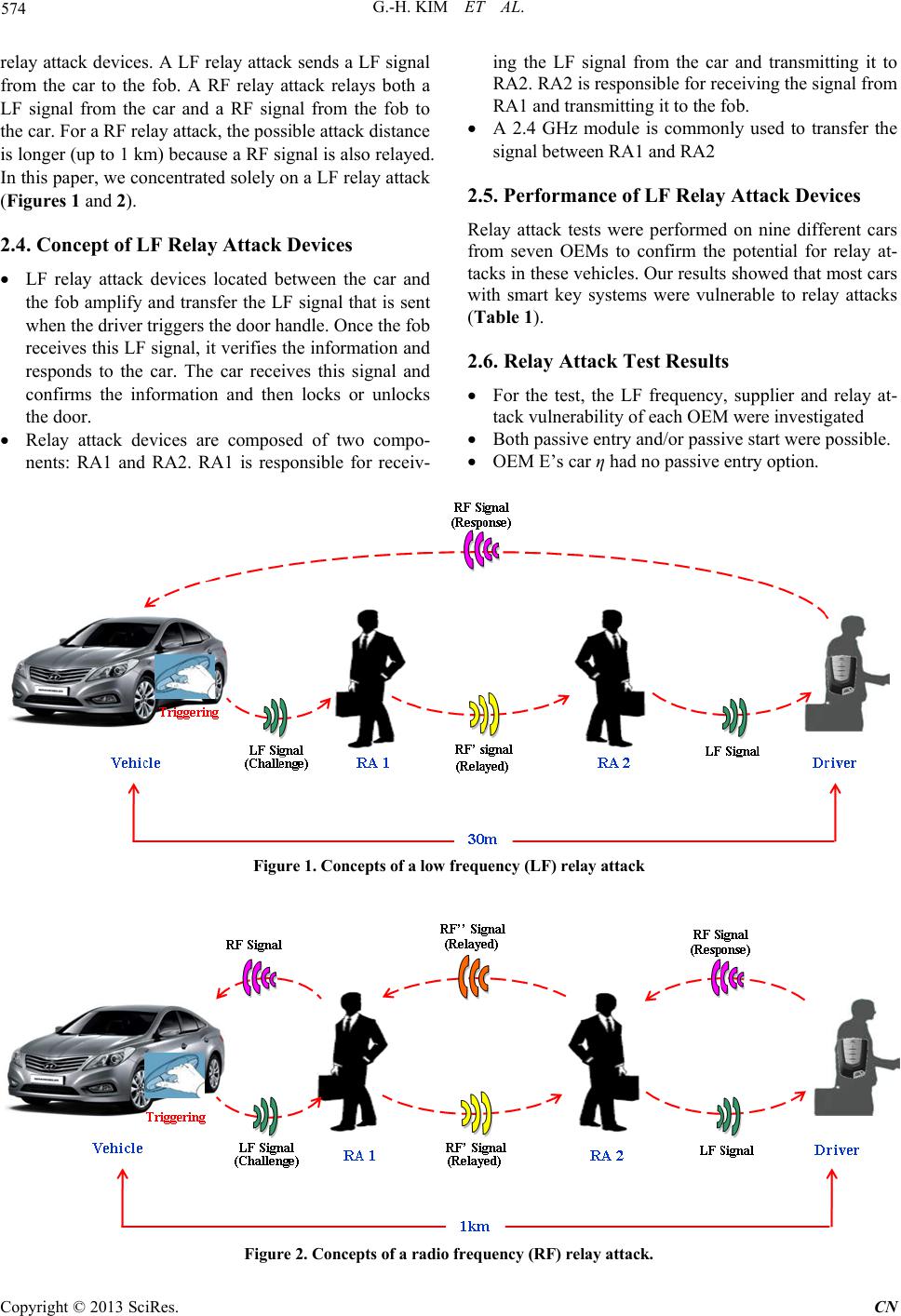
c) To consider the attenuation of the RF signal of the
fob as the battery discharges, the RSSI value of the RF
signal was measured in response to the state of the fob
battery for each direction. The distance at which the RSSI
value was measured was initially 2 m, and the gradually
increased to 50 m in 5-m increments, starting from 5 m.
The direction between the fob antenna and the car was
varied between to 0˚, 90˚ and 180˚. We did not measure
the RSSI value at 270˚ because when viewed from the
positio n of the car, the value w a s equal to 9 0˚ value.
d) For a fixed distance of 2 m, the RSSI was measured
while the fob’s battery voltage was reduced from 3.0 V
to 2.0 V in 0.2-V increments, for various directions be-
tween the fob antenna and the car of 0˚, 90˚ and 180˚.
These tests were used to confirm the minimum RSSI
value within the distance required for normal Passive En-
try.
e) Testing was performed at these test sites: and open
site, an indoor parking lot, and an outdoor parking lot.
The test results represent an average of the results ob-
tained from the three test sites (Figures 3 and 4).
2.8. Basis for Threshold Value Determination
The threshold value used to identify a relay attack must
be properly selected. If the threshold is too high, then it
could impede normal PEPS operation. The results indi-
cated that the RSSI value gradually decreases as the dis-
tance increases. Assuming that the distance over which a
driver can recognize a relay attack is 2 m, the minimum
RSSI value was acquired at a fob voltage of 2 V for 180˚
between the fob antenna and the car (Figures 5 and 6).
G.-H. KIM ET AL.
Copyright © 2013 SciRes. CN
576
Figure 3. Data acquisition equipment.
Figure 4. Data acquisition method.
2.9. Algorithm flow Chart and Verification
The proposed algorithm was successfully applied to a
smart key system. When the vehicle received the RF sig-
nal, if the RSSI value was higher than the threshold value,
then the door was unlocked; otherwise, the door re-
mained locked (Figure 7).
3. Conclusions
To avoid LF relay attacks, it is necessary to determine
whether the key is close to or far from the car based on
the received RF signal strength. We developed an algo-
rithm that measured the RSSI value and compared this
with a threshold value. If the RSSI value was lower than
the determined threshold value, then a relay attack was
perceived by the system, and the RF signal was ignored.
Thus, locked car doors remained locked, preventing entry
by the attacker.
The results of our tests on nine vehicles from seven
OEMs indicated that normal PEPS operation would be
possible for distances of <2 m (PEPS operation was not
observed for distances exceeding 2 m). However, if a
relay attack device RA1 is located near the car, and an
RF signal is transmitted from the fob, then a relay attack
could occur. In this scenario, an attack is possible be-
Figure 5. RSSI value as a function of distance and direction.
Figure 6. RSSI value as a function of direction and voltage.
Figure 7. Flow chart of relay attack avoidance algorithm.
cause the relay attack device can possibly transfer an RF
signal that was greater than the threshold value. The cur-
rent authentication method uses LF and RF one-way
communication. Two-way authentication uses LF one-way
and RF two-way communication. In future studies, mul-
ti-channel, divided packet transfer may also be consi-
dered with RF two-way authentication.
G.-H. KIM ET AL.
Copyright © 2013 SciRes. CN
577
REFERENCES
[1] A. I. Alrabady, “Security of Passive Access Vehicle,”
Submitted to the Graduate School of Wayne State Uni-
versity, Detroit, Michan.
[2] A. I. Alrabady and S. M. Mahmud, “Some Attacks
against Vehicle’s Passive Entry Security Systems and
Their Solutions,” IEEE Transactions on Vehicular Tech-
nology, Vol. 52, No. 2, March 2003.
http://dx.doi.org/10.1109/TVT.2003.808759
[3] A. I. Alrabady and S. M. Mahmud, “Analysis of Attacks
against the Security of Keyle ss-Entry Systems for Ve-
hicles and Suggestions for Improved Designs,” IEEE
Transactions on Vehicular Technology, Vol. 54, No. 1,
January 2005.
http://dx.doi.org/10.1109/TVT.2004.838829
[4] A. Francillon, B. Danev, S. Capkun, “Relay Attacks on
Passive Keyless Entry and Start Systems in Modern Cars,”
Department of Computer Science ETH Zurich 8092 Zu-
rich, Switzerland.
[5] F. Stajano, F.-L. Wong and B. Christianson, “Multichan-
nel Protocols to Prevent Relay Attack,” University of
Cambridge Computer Laboratory, Cambridge, United King-
dom, DSO National Laboratories, Singapore, University
of Hertfordshire, School of Computer Science, Hatfield,
United Kingdom.
[6] A. Leitch, “Electronic Communication Sys tem, in Partic-
ular Access Control Syste m for Passive Keyless Entry , as
well as Method for Detecting a Relay Attack Thereon,”
US Patent No. 0206989A1, 2009
[7] R. Ghabra, Y. Luo, J. Nantz and R. O. King, “Method for
Apparatus for an Anti-theft System against Radio Relay
Attack in Passive Keyless Entry/Start Systems,” US Pa-
tent No. 0143500A1, 2008
[8] R. Ghabra, N. Yakovenko and H. W. Girard, “Method
and System of determining and Preventing Relay Attack
for Passive Entry /Start Sy stem,” US Patent No. 0321154 A1,
2008
[9] H. Masudaya, “Passive Entry with Anti-theft Function,”
US Patent No. 0168997A1, 2005
[10] E. Perraud and M. Burri, “Passive Response Communica-
tion System,” US Patent No. 6992568B2, 2006
[11] C. Tieman, J. Coudre and T. P. Oman “Vehicle Security
System and Method of Operation Based on a Nomadic
device Location,” US Patent No. 201202.