 Communications and Network, 2013, 5, 485-492 http://dx.doi.org/10.4236/cn.2013.53B2089 Published Online September 2013 (http://www.scirp.org/journal/cn) Copyright © 2013 SciRes. CN Efficient Implementations of NTRU in Wireless Network Xin Zhan, Rui Zhang, Zhilong Xiong, Zhaoxia Zheng, Zhenglin Liu School of Optical and Electronic Information, Huazhong University of Science and Technology, Wuhan, China Email: liuzhenglin@hust.edu.cn Received April 2013 ABSTRACT NTRU is a lattice-based public key cryptosystem featuring reasonably short, easily created keys, high speed, and low memory requirements, seems viable for wireless network. This paper presents two optimized designs based on the en- hanced NTRU algorithm. One is a light-weight and fast NTRU core, it performs encryption only. This work has a gate-count of 1175 gates and a power consumption of 1.51 μW. It can finish the whole encryption process in 1498 μs at 500 kHz. As such, it is perfect for wireless sensor network. Another high-speed NTRU core is capable of both encryp- tion and decryption, with delays of 16,064 μs and 128,010 μs in encryption and decryption respectively. Moreover, it consists of 25,758 equivalent gates and has a total power consumption of 59.2 μW (it will be reduced greatly if low power methods were adopted). This core is recommended to be used in base stations or servers in wireless network. Keywords: Wireless Network; Public key Cryptosystem; NTRU ; Eff icient Implementations 1. Introduction The wireless network is b eing exp ected to be widely used in various fields. Although wireless network offers low- cost deployment and convenience, security implementa- tion is considered essential because of its inherent vuln e- rability. The public key cryptosystem using two different keys, such as RSA and ECC, has profo und consequences in the areas of confidentiality, key distribution and au- thentication, but its common conception is complex, slow and power hungry [1]. The relatively new lattice-based public key cryptosystem—NTRU that features reasona- bly short, easily created keys, high speed, and low mem- ory requirements [2], seems viable for wireless network. O’Rourke first implemented the NTRU core with a gate count of minimum 1483 gates (N = 503) [3]; but it performs star multiplication only. Another design is rea- lized in Kaps’s p aper (N = 167) [4]; it performs only en- cryption w ith an area of 2850 gates and power consump- tion of 15.1 μW at 500 kHz. The most detailed low-cost implementation of NTRU is realized by AC Atici’s [5]. The author presented two compact NTRU architectures (N = 167), one is for encryption only with an area of 2800 gates and a dynamic power consumption of 1.72 μW at 500 kHz. Another is capable of both encryption and decryption, and it consists of 10,500 gates and con- sumes 6 μW dynamic power. Several other papers focus on the optimization of area and power consumption, but only a few works are related to studies on the optimiza- tion of speed. In Jeffrey Hoffstein’s paper [6], an alternative of NTRU is proposed with a new form to create private key f that speeds both the key generation and the decryption. Unfortunately, there is little research on the im plementation of the enhanced NTR U. The rest of this paper is organized as follows: Section 2 summarizes the basic of enhanced NTRU algorithm; Section 3 presents the architecture of an encryption-only enhanced NTRU optimized for small area and fast speed; in Section 4, an architecture of enhanced NTRU opti- mized for high speed is presented, it is capable of both encryption and decryption; in Section 5 we give synthe- sis results on an ASI C technology library; Section 6 co n- cludes this paper. 2. Algorithm of Enhanced NTRU NTRU is a parameterized family of lattice-based public key cryptosystems. Its basic operations are realized in a truncated polynomial ring . Polyno- mials in the ring have a degree of N-1 and all the coeffi- cients are integers. Polynomial can be presented as: 2 21 01 221 1 0 NN NN Ni i i a aaX aXaXaX aX −− −− − = = +++⋅⋅⋅++ = ∑ . (1) The addition in the ring R is just as the same as general polynomial addition. But the multiplication in R is re- ferred to star multiplication (see [2] for details) and de- noted as a symbol.  X. ZHAN ET AL. Copyright © 2013 SciRes. CN The NTRU cryptosystem depends on three parameters, where a large prime N limits the degree of polynomials in the ring and satisfies . It is also possible to consider p as a polynomial, for example . In order to speed up both the key generation and the decryption process, a new form of enhanced NTRU is suggested [6]. In enhanced NTRU, users choose f to have the form . Notice that this form has the property of , so it is not necessary to compute the inverse modulo p, and the second multipli- cation in the decryption process disappears. Some other optimizations presented in the rest of this paper are all based on enhanced NTRU. Before we give an outline of enhanced NTRU algo- rithm, four sets of binary polynomials need to be specified first. Some notations are used to specify the sets of polynomials: The set of binary polynomials in . The set of binary polynomials in R with d ones and N-d zero s. Then the polynomials are selected in the specified set: , . Key Generation: the user must first choose two ran- dom polynomials and pri- vate key is computed as: . (2) Besides, must exist. Then the fol- lowing computation is performed: (3 ) Now h is the public key and f is the private key. Encryption: To encrypt a plaintext , the user should select a random polynomial at first. Then the cipher e is formed: (4 ) Decryption: In order to decrypt the cipher e using private key f, the user first calculates: (5) Then the user chooses to satisfy this congru- ence and to lie in a pre-specified subset of R. Finally, a binary polynomial m should be fou nd out to sat isfy (6) It can be proved that m equals the plaintext. 3. Light-Weight and Fast NTRU (Encryption-Only) In order to meet the requirements in ultra-low cost envi- ronments like wireless sensor network, we proposed a light-weight NTRU structure based on the enhanced NTRU algorithm. It performs encryption only and is optimized for both fast speed and small area. The parameter set we have chosen is (, )(107,64),Nq= and , which was the lowest security recommended in [2]. Figure 1 shows the architecture of light-weigh t N TRU engine. It consists of a control engine, a 6 bits result buf- fer, a multiplication module, a look up table (LUT) and a non-zero coefficients sequence generator (NCSG). The control engine manages the process of encryption. The result buffer is used to store final result and current sum in star multiplication process. The multiplication module performs star multiplication operation. Public key h is pre-computed and stored in the LUT. NCSG is designed to generate and rotate the degrees of non-zero terms of random polynomial r. Due to NCSG, one operand in multiplication operation is bounded to 1’b1 (see Section 3.1 below), the multiplier is needless and multiplication module only consists of a 6bits adder and a router. 3.1. Non-Zero Coefficients Sequence Generator (NCSG) In NTRU encryption process, the computation of is not time-efficient. In fact, r is a quite sparse binary polynomial that has only non-zero coeff icients . As a result, most of the multiplicatio ns in a star multiplication process are unnecessary. In this paper, we introduce a structure of non-zero coef- ficients sequence generator (NCSG), which could record the degrees of non-zero terms in polynomial r when the coefficients of r loaded one by one. Then the non-zero coefficients sequence is rotated during the computation of star multiplication. According to this, the control en- gine generates the corresponding address of h for LUT. As F ig u re 2 shows, NCSG consist of a bits circu- lar register, a 7 bits counter, a 7 bits adder, a 2-input rou- ter, an AND gate and an OR gate. Input of the right hand 7-bit register is composed of 2 paths and determined by a ctrl signal. Path 1 is from the most significant 7 bits during the computation of star multiplication, the register performs as a general shift register and the degree of current non-zero term is output to control engine by left-hand 7 bits register. During load- ing polynomial r, the output of the 7 bits counter is as one source of path2, it is added to the least significant 7 bits (where the degree of current term is stored). The counter counts the zero from and resets if a one is input. Then the degree of next term is computed by the adder and loaded to the circular register. After N clocks, non-zero coefficients sequence is generated in the circu- lar register.  X. ZHAN ET AL. Copyright © 2013 SciRes. CN Figure1. light-weight NTRU architecture. Figure 2. The NCSG architecture.  X. ZHAN ET AL. Copyright © 2013 SciRes. CN The clock of circular register is a gated clock based on ADD gate. During a star multiplication process ctrl equals 0 and remains high voltage, the clock is always enabled. During the loading stage where ctrl equals 1, the clock of circular register is enabled only when a one from is detected. Due to NCSG, the consumption of time to compute is reduced to clock cycles. In addition, one operand to multiplication module is 1 constantly. As a result, the hardware cost for storing polynomial r is saved. 3.2. Control Engine Control engine is the controller of the NTRU engine and designed with a 4-state finite state mach ine (FSM), which initialed with an idle state. When a valid enc signal is detected, the encryption process starts and the FSM enters a load state, during which the coefficients of polynomial r are loaded one by one to NCSG. N clock cycles later the degrees of non- zero terms are generated in NCSG. Then FSM transits to multiplication state and b egins to calculate the first coef- ficient of , this process spends clock cycles. Multiplication is followed by an add state, where plain- text m is added to the current sum. At this time, e’s first coefficient is calculated and the control engine outputs a done signal. After the addition of the message, the FSM again transmits to multiplication to compute the second coefficients of e. When the last coefficient of e is calcu- lated, the FSM returns to idle state and then the encryp- tion proce s s is finis hed. 4. High-Speed NTRU The performance gain of enhanced NTRU comes from elimination of an inversion modulo p in key generation and a star multiplication in decryption. On this basis, a high-speed NTRU engine is presented to further speed up the encryption process through improving the efficiency of star multiplication. The high-speed NTRU can be used in wireless networks that structured around base stations and centralized servers, which do not have the limitations associated with small portable devices. Figure 3 shows the architecture of the high-speed NTRU. For decryption, a 7N bits e buffer is used to store Figure 3. High-speed NTRU architecture. enc dec ... LUT result buffer(7N bits) control engine mapping module done result r_in e_in m_in 1'b1 NCSG mux e buffer(7N bits) multiplication module ... mux polynomial multiplier(PM) optional parallel PM  X. ZHAN ET AL. Copyright © 2013 SciRes. CN cipher e and another 7N bits result buffer is for the final result. Multiplication module and mapping module per- form the main arithmetic function, the former is for star multiplication (parallel polynomial multiplier is optional to further speed up the process) and the latter is used to recover plaintext m from the intermediate variable a. Moreover, LUT stores both f and h. In our design, we have chosen , , and This para- meter set of NTRU is considere d with high level of secu- rity and extremely low decryption failure probability [8]. 4.1. Mapping Module After we calculated in the decryption process, we need to recover binary plaintext m from a. The Binary polynomial m satisfies Equation [6]. According to [6], the transformation in the mapping algorithm can be summarized as: 12 12 (,,)( ,2,), ii iii a aauavwavw ++ ++ → +−+− (7) where u, v and w are obtained as: [ ] 12 [0]; {1'0,[6: 1]}; min{() / 2,}. i i ii ua v ba wav av ++ = = =++ (8) We denote this transformation as below: 12 12 ( ,,)Algorithm( ,,). ii iii i aa aaa a ++ ++ → (9) The mapping module can be implemented in a com- pletely combinational way, it performs the following function: ( ,,),&{0,1}; (,,) Algorithm( ,,),, iii i ooo iii xyz iNx xyz x y zotherwise ≥∉ = (10) where i is the value of a 7 bits counter increasing every clock cycle till i equals 2N. The connection of the mapping module and the result buffer is shown in Figure 4. When the control signal sel SASA equals zero, a mapping operation is executed and is connected to the input of the right-hand 7 bits reg- ister; when sel equals 1, the resu lt o f star multiplication is loaded to the result buffer and data is as the input to the circular register. According to the above description, the entire mapping process takes 2N clock cycles totally. 4.2. Small Hamming Weight Product To further decrease the consumption of time in computa- tion of the product , an alternative form is suggested that takes advantage of sparse polynomials [6,7]. The sug- gested form is: , where the three sparse binary polynomials , and have , and non-zero coefficients (one in this case) respec- tively. When it satisfies , the constructed polynomial r has approximately ones (occasional non-binary coefficients are mixed in with the ones and zeros, but don’t affect matters very much). Then the com- putation of is divided to three steps by , and . When combined with NCSG mentioned previously, the operation times of computing are reduced to clock cycles. For the case , we have chosen = 8. As the result, the efficiency of star multiplication in NTRU encryption tripled without changing the level of security. 4.3. Control Engine Control engine in this design has 6 states and begins with an idle state. Figure 4. The mapping unit. 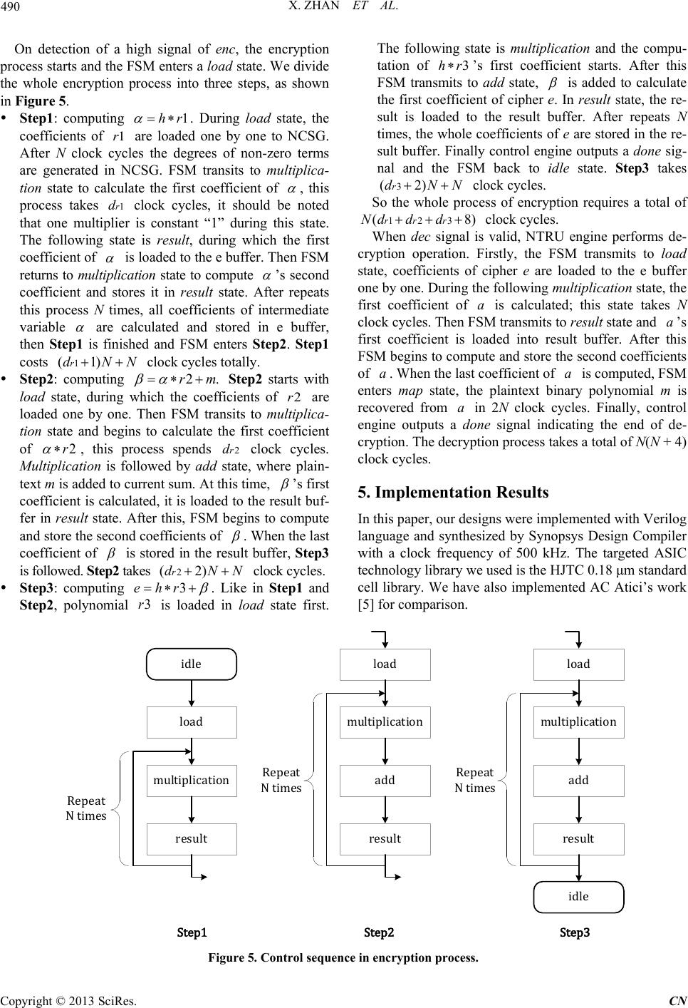 X. ZHAN ET AL. Copyright © 2013 SciRes. CN On detection of a high signal of enc, the encryption process starts and the FSM enters a load state. We divide the whole encryption process into three steps, as shown in Figure 5. Step1: computing . During load state, the coefficients of are loaded one by one to NCSG. After N clock cycles the degrees of non-zero terms are generated in NCSG. FSM transits to multiplica- tion state to calculate the first coefficient of , this process takes clock cycles, it should be noted that one multiplier is constant “1” during this state. The following state is result, during which the first coefficient of is loaded to the e buffer. Then FSM returns to multiplication state to compute ’s second coefficient and stores it in result state. After repeats this process N times, all coefficients of intermediate variable are calculated and stored in e buffer, then Step1 is finished and FSM enters Step2. S t ep1 costs clock cycles totally. Step2: computing Step2 starts with load state, during which the coefficients of are loaded one by one. Then FSM transits to multiplica- tion state and begins to calculate the first coefficient of , this process spends clock cycles. Multiplication is followed by add state, where plain- text m is added to current sum. At this time, ’s first coefficient is calculated, it is loaded to the result buf- fer in result state. After this, FSM begins to compute and store the second coefficients of . When the last coefficient of is stored in the result buffer, S t ep3 is followed. Step2 takes clock cycles. Step3: computing . Like in Step1 and Step2 , polynomial is loaded in load state first. The following state is multiplication and the compu- tation of ’s first coefficient starts. After this FSM transmits to add state, is added to calculate the first coefficient of cipher e. In result state, the re- sult is loaded to the result buffer. After repeats N times, the whole coefficients o f e are stored in the re- sult buffer. Finally control engine outputs a done sig- nal and the FSM back to idle state. Step3 takes clock cycles. So the whole process of encryption requires a total of clock cycles. When dec signal is valid, NTRU engine performs de- cryption operation. Firstly, the FSM transmits to lo ad state, coefficients of cipher e are loaded to the e buffer one by one. During the following multiplication state, the first coefficient of is calculated; this state takes N clock cycles. Then FSM transmits to resu lt state and ’s first coefficient is loaded into result buffer. After this FSM begins to compute and store the second coefficients of . When the last coefficient of is computed, FSM enters map state, the plaintext binary polynomial m is recovered from in 2N clock cycles. Finally, control engine outputs a done signal indicating the end of de- cryption. The decryption process takes a total of N(N + 4) clock cycles. 5. Implementation Results In this paper, our designs were implemented with Verilog language and synthesized by Synopsys Design Compiler with a clock frequency of 500 kHz. The targeted ASIC technology library we used is the HJTC 0.18 μm standard cell library. We have also implemented AC Atici’s work [5] for com pa rison. Figure 5. Cont rol sequence in enc ryption process . idle load multiplication result load multiplication add load multiplication add result result idle Repeat N times Repeat N times Repeat N times Step1Step2Step3 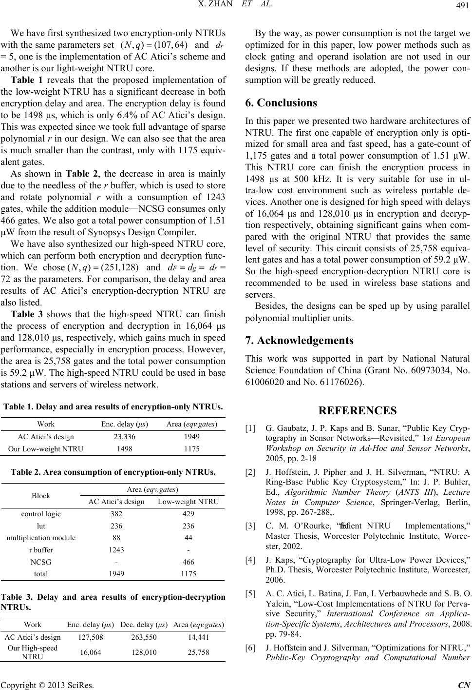 X. ZHAN ET AL. Copyright © 2013 SciRes. CN We have first synthesized two encryption-only NTRUs with the same parameters set and = 5, one is the implementatio n of AC Atici’s scheme and another is our light-weight NTRU core. Table 1 reveals that the proposed implementation of the low-weight NTRU has a significant decrease in both encryption delay and area. The encryption delay is found to be 1498 μs, which is only 6.4% of AC Atici’s design. This was expected since we took full advantage of sparse polynomial r in our design. We can also see that the area is much smaller than the contrast, only with 1175 equiv- alent gates. As shown in Table 2, the decrease in area is mainly due to the needless of the r buffer, which is used to store and rotate polynomial r with a consumption of 1243 gates, while the addition module —NCSG consumes on ly 466 gates. We also got a total power consumption of 1.51 μW from the result of Synopsys Design Compiler. We have also synthesized our high -speed NTRU core, which can perform both encryption and decryption func- tion. We chose and = 72 as the parameters. For comparison, the delay and area results of AC Atici’s encryption-decryption NTRU are also listed. Table 3 shows that the high-speed NTRU can finish the process of encryption and decryption in 16,064 μs and 128,010 μs, respectively, which gains much in speed performance, especially in encryption process. However, the area is 25,758 gates and the total power consumption is 59.2 μW. The high-speed NTRU could be used in base stations and servers of wireless network. Table 1. Delay and area results of encryption-only NTRUs. Work Enc. delay (μs) Area (eqv.gates) AC Atici’s design 23,336 1949 Our Low-weight NTRU 1498 1175 Table 2. Area consumption of encryption-only NTRUs. Block Area (eqv.gates) AC Atici’s design Low-weight NTRU control logic 382 429 lut 236 236 multiplication module 88 44 r buffer 1243 - NCSG - 466 total 1949 1175 Table 3. Delay and area results of encryption-decryption NTRUs. Work Enc. delay (μs) Dec. delay (μs) Area (eqv.gates) AC Atici’s design 127,508 263,550 14,441 16,064 128,010 25,758 By the way, as power consumption is not the target we optimized for in this paper, low power methods such as clock gating and operand isolation are not used in our designs. If these methods are adopted, the power con- sumption will be greatly reduced. 6. Conclusions In this paper we presented two hardware architectures of NTRU. The first one capable of encryption only is opti- mized for small area and fast speed, has a gate-count of 1,175 gates and a total power consumption of 1.51 μW. This NTRU core can finish the encryption process in 1498 μs at 500 kHz. It is very suitable for use in ul- tra-low cost environment such as wireless portable de- vices. Another one is designed for high speed with delays of 16,064 μs and 128,010 μs in encryption and decryp- tion respectively, obtaining significant gains when com- pared with the original NTRU that provides the same level of security. This circuit consists of 25,758 equiva- lent gates and has a total power consumption of 59.2 μW. So the high-speed encryption-decryption NTRU core is recommended to be used in wireless base stations and servers. Besides, the designs can be sped up by using parallel polynomial multiplier units. 7. Acknowledgements This work was supported in part by National Natural Science Foundation of China (Grant No. 60973034, No. 61006020 and No. 61176026). REFERENCES [1] G. Gaubatz, J. P. Kaps and B. Sunar, “Public Key Cryp- tography in Sensor Networks—Revisited,” 1st European Workshop on Security in Ad-Hoc and Sensor Networks, 2005, pp. 2-18 [2] J. Hoffstein, J. Pipher and J. H. Silverman, “NTRU: A Ring-Base Public Key Cryptosystem,” In: J. P. Buhler, Ed., Algorithmic Number Theory (ANTS III), Lecture Notes in Computer Science, Springer-Verlag, Berlin, 1998, pp. 267-288,. [3] C. M. O’Rourke, “Efficient NTRU Implementations,” Master Thesis, Worcester Polytechnic Institute, Worce- ster, 2002. [4] J. Kaps, “Cryptography for Ultra-Low Power Devices,” Ph.D. Thesis, Worcester Polytechnic Institute, Worcester, 2006. [5] A. C. Atici, L. Batina, J. Fan, I. Verbauwhede and S. B. O. Yalcin, “Low-Cost Implementations of NTRU for Perva- sive Security,” International Conference on Applica- tion-Specific Systems, Architectures and Processors, 2008. pp. 79-84. [6] J. Hoffstein and J. Silverman, “Optimizations for NTRU,” Public-Key Cryptography and Computational Number  X. ZHAN ET AL. Copyright © 2013 SciRes. CN Theory: Proceedings of the International Conference or- ganized by the Stefan Banach International Mathematical Center Warsaw, Poland, September 11-15, 2000, p. 77. [7] J. Hoffstein and J. H. Silverman, “Random Small Ham- ming Weight Products with Applications to Cryptogra- phy,” Discrete A ppli e d Mathematics, Vol. 130, No. 1, 2003, pp. 37-49. [8] J. H. Silverman and W. Whyte, “Estimating Decryption Failure Probabilities for NTRUencrypt,” Technical Re- port, NTRU Cryptosystems, 2005, Technical Report No. 18, Version 1.
|