Communications and Network, 2013, 5, 461-466
http://dx.doi.org/10.4236/cn.2013.53B2085 Published Online September 2013 (http://www.scirp.org/journal/cn)
Copyright © 2013 SciRes. CN
Network-Load A ware Adaptive Channel Access
Contr ol for WLAN*
Xiaoyan Wu1, Qinghe Du1,2, Pinyi Ren1
1School of Electronic and Information Engineering, Xi’an Jiaotong University, Xi’an, China
2National Mobile Communications Research Laboratory of Southeast University, Nanjing, China
Email: xywu09@stu.xjtu.edu.cn, duqinghe@mail.xjtu.edu.cn, pyren@mail.xjtu.edu.cn
Received June 2013
ABSTRACT
Wireless local area network (WLAN) brings us a low cost and high bandwidth experience and thus plays a critically
important role in current/future networks to support high-rate transmissions. To better pro vide quality-of-servic e (QoS)
for WLAN users, we in this paper propose an improved scheme called “A-EDCA (adaptive EDCA), based on en-
hanced distributed channel access (EDCA) of IEEE 802.11e under the infrastructure mode. Our proposed scheme aims
at efficiently adapting the transmission ove r WLAN to the time-varyin g network condition s and mitigating the competi-
tion ability unfairness between access point (AP) and non-AP stations (STAs). Specifically, all non -AP STAs adaptive-
ly modify the contention window based on the network condition. Moreover, AP skips the backoff phase by setting its
backoff coun ter as zero when non-AP STA completes transmission successfully to re lieve the unfairness. At last, sim u-
lation results d emonstra t e the effectivene ss of the pro p os ed appr oa c h .
Keywords: Quality of Service (QoS); IEEE 802.11e; Enhanced Distributed Channel Access (EDCA)
1. Introduction
Due to the characteristics of the high bandwidth, low cost
and easy deployment, WLAN has surrounded us ev ery-
where. WLAN has two kinds of modes, one with AP and
the other without AP. The former mode is adopted in the
most practical deployments. Hence, we consider the mode
with AP (also called infrastructure mode). Traditional IEEE
802.11 protocol offers us two access policies, namely,
DCF (distributed coordination function) and PCF (point
coordination function) [1]. DCF is a policy based on
competition and PCF is based on polling. Both DCF and
PCF cannot provide QoS guarantees. To accommodate
QoS, IEEE 802.11e is proposed including EDCA (en-
hanced distributed channel access) mode and HCCA (HCF
controlled channel access) mode [2]. Most network de-
vices are based on EDCA due to its easy realization and
good expansibility.
Therefore, we only discuss EDCA policy in this paper.
In EDCA, some important parameters including AC (access
category), AIFS (arbitrary inter-frame space) and TXOP-
limit (transmission opportunity limit) are adopted. Differ-
ent services have different parameters for QoS support.
However, there a re sti ll some problems whe n usi ng EDCA.
Specifically, stations may suffer from performance de-
gradations and radio resources are not fully utilized due
to the fixed parameter settings. When the number of sta-
tions increases, the probability of collisions increases
leading to frequent retransmissions and a decrease of the
overall throughput [3]. In addition, there exists unfairness
of channel access competition ability between AP and
non-AP stations (STAs) which is because that AP almost
has the same channel access competition ability with one
non-AP STA while the number of non-AP STAs is far
larger than that of AP. This causes that AP cannot handle
the data in time.
For providing better QoS, many analytical approaches
are proposed. Bianchi [4] developed a simple DTMC (dis-
crete time Markov chain) and the saturation throughput
was obtained by applying regenerative analysis to a ge-
neric slot time. In [5], authors represented an analytical
model to analyze the performance of EDCA. Cali et al.
[6] employed renewal theory to analyze a p-persistent
variant of DCF with persistence factor p derived from the
C.W. Tay et al. [7] instead used an average value ma-
thematical method to model the DCF backoff procedure
*
The research reported in this paper was supported by the National
Natural Science Foundation
of China under Grant No. 61102078, the
National Science and Technology Major Project under Grant No.
2013ZX03002003-
004, the Specialized Res earch Fu nd f or the Doctoral
Program of Higher Education under Grant No. 20110201120014, the
Open Research Fund of N
ational Mobile Communications Research
Laboratory, Southeast Universit y (No.
2011D10), and the Fundamental
Research Funds for the Central University.
X. Y. WU ET AL.
Copyright © 2013 SciRes. CN
462
and to calculate the average number of interruptions that
the backoff timer experienced. The throughput and delay
for EDCA were derived based on Markov Chain [8,9]. In
order to realize QoS guarantees, researchers have pro-
posed many approaches. A large proportion of these ap-
proaches are based on EDCA [10-15].
In this paper, we propose an improved scheme “A-
EDCA based on EDCA with a low computation com-
plexity. Firstly, we adjust the contention window (CW)
adaptively according to the current network load condi-
tion so as to make full use of the wireless channel re-
source. Secondly, we adjust channel access policy of AP.
The remainder of this paper is organized as follows: in
Section 2, we present the system model and the brief
summary of EDCA policy. The design and detailed pro-
cedures of our proposed scheme are given in Section 3.
The performance analysis is given in Section 4. We show
and analyze the simulation results in Section 5. Finally,
we conclude our work in Section 6.
2. System Model
2.1. System Model
We consider the infrastructure mode of WLAN. There
are N non-AP STAs distributed randomly and one AP in
WLAN. Each non-AP STA transmits/receives packets
through AP and there are no packet transmissions be-
tween non-AP STAs. We assume that the channel is ideal
and that all STAs (including AP and non-AP STAs) are
still for simplicity. The scenario is depicted in Figu re 1.
Without loss of generality, we consider two kinds of traffics:
voice traffic and background traffic. As we know, voice
traffic is delay-sensitive and has higher priority than back-
ground traffic. Because some problems exist when ED-
CA policy is used directly, we propose an improved chan-
nel access scheme called “A-EDCA.
2.2. Enhanced Distributed Channel Access
This subsection briefly summarizes the operations of IEEE
Figure 1. Scenario with N non-AP STAs and one AP.
802.11e EDCA. For detailed description, readers may
refer to [1,2]. EDCA is an enhanced policy of DCF.
There are some important notions, as depicted by Table
1. The packets from upper layer are classified into four
ACs. Each AC is corresponding to one queue. Each STA
has four queues and each queue has a backoff counter.
The mapping from upper layer to medium access control
(MAC) layer is shown as Figure 2 (refer to [2]). In EDCA,
the channel acces s process is described as following. STA
which has packets to send senses the channel. If the
channel is idle for AIFS period, th e STA transmits pack-
ets immediately. If the channel is busy, the backoff coun-
ter is initialized and set as a value based on the backoff
mechanism. The STA enters the backoff phase after it
senses the channel idle for AIFS period. In the backoff
phase, the backoff counter decreases by one if the chan-
nel is idle for one time slot (TS) consecutively. If the
channel becomes busy, the backoff counter is suspended.
The counter resumes when the STA senses the channel
idle for AIFS period again. The STA transmits packets if
the backoff counter decreases to zero. The node can tr ans-
mit multiple packets during TXOP. When the STA suc-
cessfully transmits data, its CW is set as CWmin and its
backoff counter is set as a value from [0, CW 1] ran-
domly. The channel access process is illustrated as Fig-
ure 3 (refer to [2] ).
There exist two kinds of collisions in EDCA, namely,
virtual collisions and inter-STA collisions. The former
occurs when more than two queues (including two queues)
in a STA simultaneously attempt to transmit packets.
Table 1. Notions and Comments.
Notion Comment
TS time slot
SIFS short inter-frame space
DIFS distributed inter-frame space
AIFS arbitrary inter-frame space
CW contention window
CWmin minimum contention window
AC access category
TXOP transmission opportunity
retrylim maximum retransmission time
Figure 2. The mapping from upper layer to medium access
control (MAC) layer.
X. Y. WU ET AL.
Copyright © 2013 SciRes. CN
463
Figure 3. Channel Access Process in Enhanced Distributed
Channel Access (EDCA) .
The queue with the highest priority wins and attempts to
transmit data while the others do not send data but upd ate
their CWs according to the backoff mechanism depicted
in Equations (1)-(2) and continue to sense the channel.
(1)
(2)
The latter collision happens when there are more than
two STAs (including two STAs) simultaneously transmit
data. The STAs participating in the collision all update
their CWs according to the backoff mechanism depicted
in Equations (1)-(2), and increase retry number (denoted
by retrynum) by one. Then all stations sense the channel
for the next attempt again.
3. A-EDCA Channel Access Policy
In this section, we present A-EDCA channel access pol-
icy. To begin with, we present the general idea of
A-EDCA. Then the detailed description is given.
3.1. Proposed A-EDCA Channel Access Policy
There exist problems when EDCA policy is used directly.
It cannot indicate how crowded the channel becomes that
a certain station either succeeds to transmit packets or
collides with others. In order to adapt to the network load
condition, we have to find a metric that can reflect what
the current load condition is like. From the backoff me-
chanism we know that the more crowded the WLAN is,
the bigger the retrynum becomes. Therefore, we adopt the
average value of retrynum (denoted by E[retrynum]) as the
metric. In order to provide AP with the bigger channel
access opportunity to relieve th e un fair ness, we adjust the
channel access policy of AP. After a certain non-AP STA
transmits packets successfully we set the backoff counter
of AP as zero so as to make AP skip the backoff phase
and attempt to transmit data in the next time.
3.2. Detailed Description of A-EDCA
3.2.1. CW Value Adjustment
When a certain STA (including AP) succeeds to transmit
packets we calculate E[retrynum] using Equation (3).
(3)
Here, M is the number of stations whose retrynum > 0.
The channel is not busy if E[retrynum] and the
channel becomes crowded if E[retrynum] . We com-
pare E[retrynum] with the threshold (denoted by ) and
update CW according to Equation (4).
(4)
When collision occurs, we compute E[retrynum] using
Equation (3) and update the CW of the stations partici-
pating in the collision using Equations (1) (2) and (5).
(5)
3.2.2. Channel Access Policy Adjustment for AP
When a non-AP STA succeeds to transmit packets, AP
sets its backoff counter as zero which makes AP skip the
backoff phase. Then AP can attempt to transmit data af-
ter AIFS period during which the channel is continuously
idle. This adjustment relieves the unfairness between the
channel access competition ability of non-AP STAs and
that of AP, depicted in Figure 4. We emphasize that the
policy that we set backoff counter of AP as zero is
adopted only when non-AP STA completes transmission
successfully, which is for the sake of avoiding AP occu-
pying the channel all the time.
The algorithm is presented in pseudo-code in Table 2.
4. Performance Analysis
The section is based on [8]. For simplicity, we only con-
sider two ACs without loss of generality, namely, AC0
which prese nt s bac kground traffic a nd AC3 which presents
voice traffic. We assume that each station only includes
one AC. In order to obtain the expressions of perfor-
mance metrics, some equations are given as follows. The
probability that a station of ACi transmits data in a
slot is shown by
Figure 4. Channel Access Policy Adjustment of AP in A-EDCA.
X. Y. WU ET AL.
Copyright © 2013 SciRes. CN
464
Table 2. A-EDCA Algorithm.
Algorithm 1. A-EDCA
01. Initialization
02. if Transmission completes successfully for nodei then
03. Calculate E[retrynum] using equation (3);
04. if nodei is AP then
05. if E[retrynum]
λ
<
then
06. CW(i)
CWmin
07. else
08. CW(i) does not change;
09. end if
10. else
11. Set backoff counter of AP as zero;
12. Do steps 5-9;
13. end if
14. end if
15. if Collision occurs in which nodei,j,k,… (denoted by A) partici-
pate then
16. Calculate E[retrynum] using equation (3);
17. if E[retrynum]
18. Update CWs of STAs according to (1) and (2)
19. else
20. CWs do not change;
21. end if
22. end if
1
0,0,0
1
0,0
(1 )0,
(1 )
13.
1
r
I
ir
pi
pP
pi
p
β
τ
α
+
+
=
=
=
(6)
where r is retrylim, p is the collision probability that a
frame encounters,
0,0,0
β
and
0,0
α
are steady prob abili-
ties referred to [8], and PI is the probability that the
channel is idle in a time slot, given by PI = q1/(1+q1 q2).
Here, q1 and q2 is the probability that there are no trans-
missions in a slot during an AIFS period and during oth er
period respectively, depicted as follows:
3
03
13
203
(1 )
(1) (1)
n
nn
q
q
τ
ττ
= −
=−−
(7)
where ni is the number of stations of ACi. The probability
PB that a slot is busy is given by PB = 1 PI. The proba-
bility Psi that a station of ACi succeeds to transmit data in
a slot time is shown by
3
0
13
1
10
(1) (1)0,
(1 )
(1) (1)3.
i
i
i
nn
ii in
SiiiiB
nn
ii i
ni
Pn P
ni
ττ τ
ττ
ττ τ
−− =
= −
+− −=
(8)
The probability PC that collisions happen in a slot time
is given by
1
C IS
P PP=−−
.
According to [8], throughput (denoted by S) is pre-
sented as follows:
[ ][]
S
SPEPE TS= ∗
(9 )
where PS is the probability that a successful transmission
occurs in a slot time depicted by
03Ss s
PPP= +
,
[]EP
is the average size of frame, and E[TS] is the average
length of a time slot given by E[TS] = PI
σ
+ PSTS +
PCTC. Here,
σ
is the length of a time slot, TS is the av-
erage time of successful transmission, and TC is the av-
erage time of collision. The TS and TC in the basic mode
are presented by
[ ]
[ ]
[ ]
AC
C timeout
Si
THE PSIFSACK
THE PSIFSACKAIFS
=+++
=++++
(10)
where H is the size including both MAC head and PHY
head, E[P] is the size of frame. From (9) we know that S
is a decrea s i ng functi on of collision pr obabili t y p.
The mean access delay (denoted by E[D]) is shown as
follows:
1
1
0
1
()
2
[][ ]
1
ir i
r
r
i
W
pp
EDE TS
p
+
+
=
+


= ⋅




(11)
We can derive that E[D] is an increasing function of
collision probability p.
By using A-EDCA policy without considering AP pol-
icy the collision probability can be decreased efficiently
especially when the number of stations becomes large.
From (9) (11) we can know that the throughput is im-
proved and that delay is decreased by using A-EDCA
policy. Taking AP policy adjustment into account, we can
know that the downlin k throughput can be improved and
that the unfairness can be relieved.
5. Simulation Results
We adopt throughput, mean end-to-end delay and fair-
ness of throughput to compare the performance between
A-EDCA policy and EDCA policy. The fairness of
throughput (denoted by I) is defined as the ratio of the
difference between uplink throughput and downlink
throughput to the throughput of uplink, depicted as Equ-
ation (12).
( )
up down up
ITT T= −
(12)
where Tup and Tdown denote uplink throughput and down-
link throughput, respectively.
We make some assumptions in our simulation. The
channel is ideal and packet loss ratio (PLR) is only in-
troduced by the event that the retransmission time is up
to retrylim. Only two kinds of traffic are considered which
are voice traffic (denoted by AC3) and background traffic
(denoted by AC0). TXOP is set as zero for all nodes,
which means that the node occupying the channel suc-
cessfully can o nly tr ans mit on e p acket. We adopt the basic
access mode. Simulation parameters are listed in Ta ble 3.
Due to the dynamic adjustment of CW and AP channel
access policy adjustment, the probability of collisions can
X. Y. WU ET AL.
Copyright © 2013 SciRes. CN
465
be decreased and AP can get more opportunity to access
the shared channel, which improves the performance of
throughput, end-to-end delay and relieves the unfairness
between AP a nd non-AP STAs.
Figure 5 shows the performance comparison between
Table 3. Simulation Parameters.
Parameters value
PHY Header 192 bits
MAC Header 272 bits
SIFS 1 Time Slot
DIFS 3 Time Slot
AIFSN[AC0] 7
AIFSN[AC3] 2
ACK Frame PHY Header + 112 bits
ACKtimeout ACK Frame + DIFS
Data Rate 11 Mbps
Time Slot 20 μs
retrylim 7
AC0 1500 bytes
AC3 200 bytes
CW[AC0] {31, 63, 127, 255, 511, 1023}
CW[AC3] {7, 15, 31, 63, 127, 255}
(a)
(b)
Figure 5. (a) Comparison of Throughput When No. of STAs
Changes; (b) Comparison of Mean End-to-End Delay When
No. of STAs Changes.
A-EDC A a nd EDCA whe n t he num be r of stations changes.
Figure 5(a) illustrates that throughput under A-ED CA is
larger than that under EDCA. Figure 5(b) shows that
mean end-to-end delay becomes smaller under A-EDCA.
From Fig u res 6(a) and (b) we can see that our A-EDCA
brings performance improvements when the packet ar-
rival rate changes. The cumulative distribution function
of mean end-to-end delay is shown in Figure 7(a). We
can see that about 90 percent of delay is under 400 ms
under A-EDCA policy while it is 500 ms under EDCA
policy. Figure 7(b) shows us that the unfairness is re-
lieved under A-EDCA especially when the number of
stations is large.
6. Conclusion
This paper has considered the problem of IEEE 802.11e
EDCA policy which includes not adapting to the time-
varying network condition due to the fixed parameter
settings and the channel competition ability unfairness
between AP and non-AP STAs. In order to solve the
problem, we proposed an improved scheme “A-EDCA.
(a)
(b)
Figure 6. ( a) C omp arison of Thr oughput When Packet Arrival
Rate Changes; (b) Comparison of Mean End-to-End Delay
When Packet Arrival Rate Changes.
50 55 60 65 70 75 80
0
2
4
6
8
10
12
14
16 x 10
4
Number of St aion s
Thr o ug hp ut (bit/s )
v oice under EDCA
v oice under A-EDCA
data und e r EDCA
data under A-EDCA
tot al under EDCA
tot al under A- EDCA
50 55 6065 70 75 80
0
50
100
150
200
250
300
350
Number of St aion s
Me an End -to-End Delay (ms)
v oice under EDCA
v oice under A-EDCA
data und e r EDCA
data under A-EDCA
12345678
0.2
0.4
0.6
0.8
1
1.2
1.4
1.6
1.8
2
2.2 x 10⁵
Packet Ar r iv al Rate
Thr o ug hp ut (bit/s )
voice under EDCA
voice under A-EDCA
data un de r EDCA
data under A- EDCA
total under EDCA
total under A-EDCA
12345678
0
50
100
150
200
250
300
350
400
Packet Ar r iv al Rate
Me an End-to -End Delay (ms )
voice under EDCA
voice under A-EDCA
data un de r EDCA
data under A- EDCA
X. Y. WU ET AL.
Copyright © 2013 SciRes. CN
466
(a)
(b)
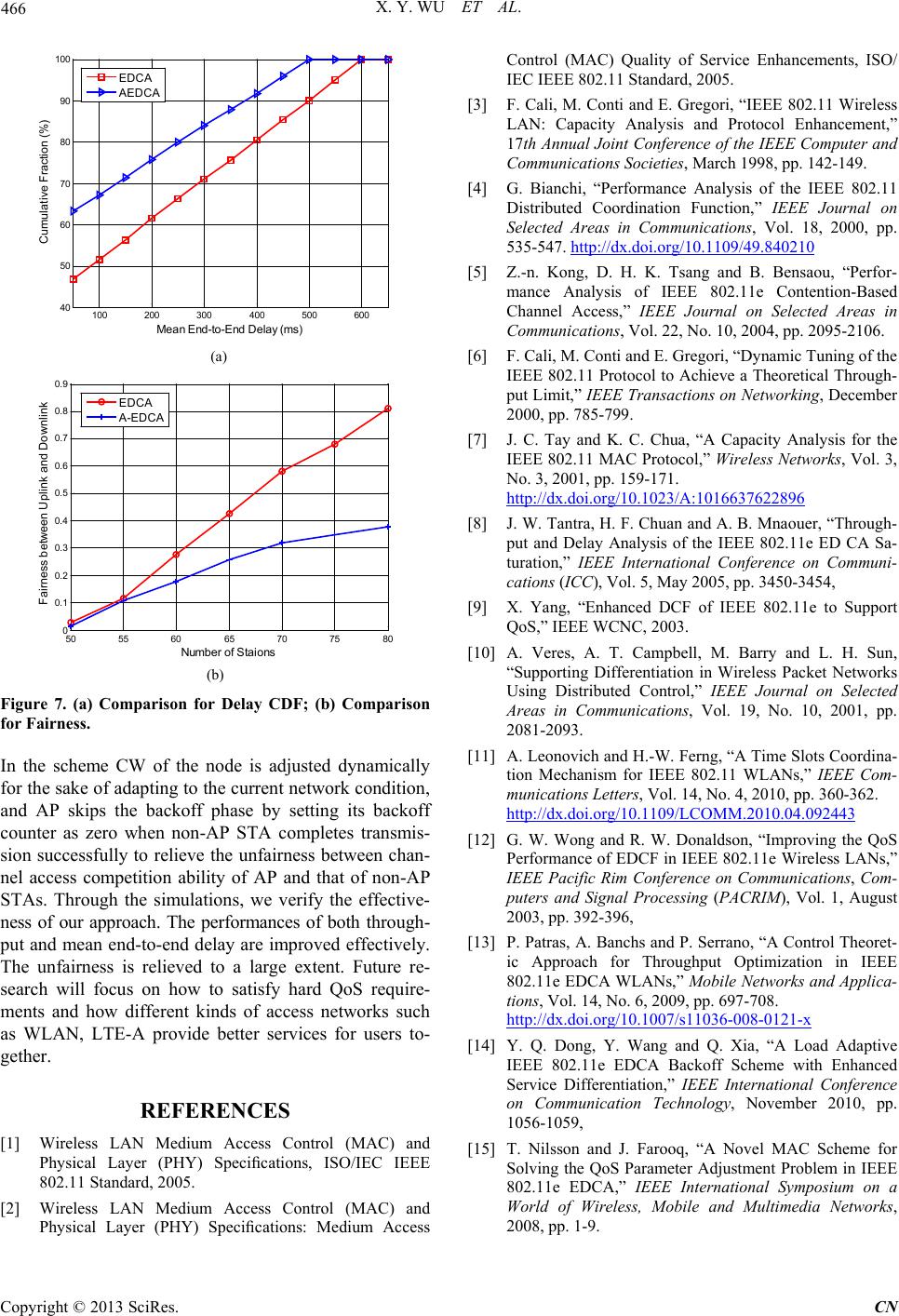
Figure 7. (a) Comparison for Delay CDF; (b) Comparison
for Fairness.
In the scheme CW of the node is adjusted dynamically
for the sake of adapting to the current network condition,
and AP skips the backoff phase by setting its backoff
counter as zero when non-AP STA completes transmis-
sion successfully to relieve the unfairness between chan-
nel access competition ability of AP and that of non-AP
STAs. Through the simulations, we verify the effective-
ness of our approach. The performances of both through-
put and mean end-to-end delay are improved effectively.
The unfairness is relieved to a large extent. Future re-
search will focus on how to satisfy hard QoS require-
ments and how different kinds of access networks such
as WLAN, LTE-A provide better services for users to-
gether.
REFERENCES
[1] Wireless LAN Medium Access Control (MAC) and
Physical Layer (PHY) Specifications, ISO/IEC IEEE
802.11 Standard, 2005.
[2] Wireless LAN Medium Access Control (MAC) and
Physical Layer (PHY) Specifications: Medium Access
Control (MAC) Quality of Service Enhancements, ISO/
IEC IEEE 802.11 Standard, 2005.
[3] F. Cali, M. Conti and E. Gregori, “IEEE 802.11 Wireless
LAN: Capacity Analysis and Protocol Enhancement,”
17th Annual Joint Conference of the IEEE Computer and
Communications Societies, March 1998, pp. 142-149.
[4] G. Bianchi, “Performance Analysis of the IEEE 802.11
Distributed Coordination Function,” IEEE Journal on
Selected Areas in Communications, Vol. 18, 2000, pp.
535-547. http://dx.doi.org/10.1109/49.840210
[5] Z.-n. Kong, D. H. K. Tsang and B. Bensaou, “Perfor-
mance Analysis of IEEE 802.11e Contention-Based
Channel Access,” IEEE Journal on Selected Areas in
Communications, Vol. 22, No . 10, 2004, pp. 2095-2106.
[6] F. Cali, M. Conti and E. Gregori, “Dynamic Tuning of the
IEEE 802.11 Protocol to Achieve a Theoretical Through-
put Limit,” IEEE Transactions on Networking, December
2000, pp. 785-799.
[7] J. C. Tay and K. C. Chua, “A Capacity Analysis for the
IEEE 802.11 MAC Protocol,” Wirele ss Networks, Vol. 3,
No. 3, 2001, pp. 159-171.
http://dx.doi.org/10.1023/A:1016637622896
[8] J. W. Tantra, H. F. Chuan and A. B. Mnaouer, “Through-
put and Delay Analysis of the IEEE 802.11e ED CA Sa-
turation,” IEEE International Conference on Communi-
cations (ICC), Vol. 5, May 2005, pp. 3450-3454,
[9] X. Yang, “Enhanced DCF of IEEE 802.11e to Support
QoS,” IEEE WCNC, 2003.
[10] A. Veres, A. T. Campbell, M. Barry and L. H. Sun,
“Supporting Differentiation in Wireless Packet Networks
Using Distributed Control,” IEEE Journal on Selected
Areas in Communications, Vol. 19, No. 10, 2001, pp.
2081-2093.
[11] A. Leonovich and H.-W. Ferng, “A Time Slots Coordina-
tion Mechanism for IEEE 802.11 WLANs,” IEEE Com-
munications Letters, Vol. 14, No. 4, 2010, pp. 360-362.
http://dx.doi.org/10.1109/LCOMM.2010.04.092443
[12] G. W. Wong and R. W. Donaldson, “Improving the QoS
Performance of EDCF in IEEE 802.11e Wireless LANs,”
IEEE Pacific Rim Conference on Communications, Com-
puters and Signal Processing (PACRIM), Vol. 1, August
2003, pp. 392-396,
[13] P. Patras, A. Banchs and P. Serrano, “A Control Theoret-
ic Approach for Throughput Optimization in IEEE
802.11e EDCA WLANs,” Mobile Networks and Applica-
tions, Vol. 14, No. 6, 2009, pp. 697-708.
http://dx.doi.org/10.1007/s11036-008-0121-x
[14] Y. Q. Dong, Y. Wang and Q. Xia, “A Load Adaptive
IEEE 802.11e EDCA Backoff Scheme with Enhanced
Service Differentiation,” IEEE International Conference
on Communication Technology, November 2010, pp.
1056-1059,
[15] T. Nilsson and J. Farooq, “A Novel MAC Scheme for
Solving the QoS Parameter Adjustment Problem in IEEE
802.11e EDCA,” IEEE International Symposium on a
World of Wireless, Mobile and Multimedia Networks,
2008, pp. 1 -9.
100 200 300400500 600
40
50
60
70
80
90
100
Mean End-to- End Del ay (ms)
Cumulative Fract ion (% )
EDCA
AEDCA
50 55 6065 70 7580
0
0.1
0.2
0.3
0.4
0.5
0.6
0.7
0.8
0.9
N um ber of St aions
Fairn es s be twee n Uplink a nd Downlink
EDCA
A-EDCA