Modern Instrumentation, 2013, 2, 68-73
http://dx.doi.org/10.4236/mi.2013.24010 Published Online October 2013 (http://www.scirp.org/journal/mi)
Copyright © 2013 SciRes. MI
Hot Blast Flow Measurement in Blast
Furnace in Straight Pipe
Ricardo S. N. Motta1, Edson C. Bortoni2, Luiz E. Souza3
1CSN/USS/UNIFEI, Volta Redonda, Brazil
2ISEE/UNIFEI, Itajubá, Brazil
3IESTI/UNIFEI, Itajubá, Brazil
Email: nadur@CSN.com.br, bortoni@unifei.edu.br, edival@unifei.edu.br
Received October 23, 2012; revised February 12, 2013; accepted August 22, 2013
Copyright © 2013 Ricardo S. N. Motta et al. This is an open access article distributed under the Creative Commons Attribution Li-
cense, which permits unrestricted use, distribution, and reproduction in any medium, provided the original work is properly cited.
ABSTRACT
This article shows an innovative method to model and validate the hot air flow through the blast furnacés tuyeres. This
study will be the basis for flow measurements implementation and safety interlocks for the pulverized coal injection.
The flow measurements were taken in the blast furnace down leg pipes by installing refractory Venturi tubes. The sys-
tem for the calculation of differential pressure takes into consideration the dimension of the Venturi, the air density and
compressibility. The objective is to specify the flow transmitters required to automate a control system and implement
safety interlocks for the coal injection plant.
Keywords: Blast Furnacés Tuyeres; Straight Pipe; Hot Air Flow; Coal Injection
1. Introduction
The aim of this work is to create a valid calculation me-
thod to obtain a correct adjustment for the Delta P flow
transmitters used in a special blast furnace equipment
known as Straight Pipe Venturi (SPV). The SPV has got
an internal refractory Venturi with differential impulse
pressure pipes installed to reach the Venturi inlet and
restrictions pressures.
The final subject is to implement safety interlocks for
pulverized coal injection (PCI) in the blast furnace (BF).
These researches and implementations were carried out
in the BFs 2 and 3 of Companhia Siderúrgica Nacional
(CSN) at Volta Redonda-Rio de Janeiro State-Brazil.
The hot blast air flow system in the straight tubes
needs a differential pressure transmitter for the flow
measurements to accomplish the safety interlocks of the
BF with PCI. These intelligent analogical flow transmit-
ters monitor the air blown through the straight pipes of
each blowpipe. They will indicate if the tuyere is blocked
or if the blast air flow is low for any reason.
For CSN’s BF3, e.g., this low flow limit was initially
established in 80 m3/min at NTP conditions. When this
limit is reached, the coal valve in the distributor will
close and a high pressure nitrogen valve for purge and
cooling the lance will open, avoiding the accumulation of
coal inside the down leg (also known as straight pipe)
tubes and the blowpipe.
A blockage in the blowpipe or in tuyeres, due to crust
accumulation of the injected or a not burning coal inside
the straight and blowpipe tubes may cause a explosion at
casthouse floor and a BF emergency stop.
In the calculation of this work, the real conditions of
the air blown through the process were considered. The
values and the methods were enhanced from Motta’s [1],
using considerations of Delmeè [2] and Bortoni [3].
2. Nomenclature
The nomenclature used is described below:
T0-NTP temperature (273 K);
P0-NTP pressure (101.327 kPa);
Ts-Temperature of the hot blast air in (K);
Ps-Pressure of the hot blast air in (kgf/cm2);
Z-Compressibility factor for th e hot blast air;
V1, V2-Flow average speed in (m/s);
Z1, Z2-Highness in points 1 and 2 respectively in (m);
P1, P2-Pressure in the points 1 and 2;
G-Gravity acceleration = 9.81 (m/s2);
P
-Differential pressure through the Venturi (Pa);
D-Entrance internal pipe diameter in (m);
d-Restriction I nternal pipe diam eter in (m);
a-Restriction area of di ameter d;
-Isentropic expansion factor;
R. S. N. MOTTA ET AL.
Copyright © 2013 SciRes. MI
69
D-Entrance Venturi diameter at TS;
d-Venturi diameter at TS;
H
-SiC2 dilation factor = 5.1 × 10⁶·˚C1
L
-Alumina dilation factor = 6 × 10⁶·˚C1
Q-Straight pipe flow measured in (m3/min);
Q0-Straight pipe flow in (m³/min) at NTP;
QM-Motoblower flow in (m³/min) at NTP;
QT-Sum of stra i ght pi pe flows in (m³/min) at N TP ;
Tamb-Temperature where D and d are taken (25˚C);
OAir
-Blown air density at NTP conditions (kg/m³);
Air
-Air density at BF process conditions.
3. Process Description
The BF has the objective of extracting the hot metallic
iron from ore, sinter, coke and coal. This is made by a
hot enriched air flow passing through a burden of ore,
coke, sinter and calcareous, that goes down in a internal
column of the BF. The pulverized coal injection in the
BF tuyeres replaces partially the coke charged on the top.
The PCI increases the hot metal production and de-
creases the cost and environmental pollution, due to less
coke needed.
The hot blast air is blown and distributed at the bottom
of bf through the straight pipes, blowpipes and finally the
tuyeres. This set is connected to the main bustle as Fig-
ure 1 shows. The air blown for the bf process is provided
by the motoblowers. They blow atmosphere air into the
hot stoves, and in this process, the temperature is raised
up to about 200˚C. When this cold air passes through the
hot stoves, temperature raises up to 1.100˚C or 1.200˚C.
The hot air blow system is consisted of four hot stoves
working in a parallel in a combination. While two are
heating up, the other two are blowing hot air to the main
bustle. The bustle has the purpose of distributing the
heated up air from the hot stoves to the bottom of the BF.
The main equipments of this set are the straight tubes, the
blowpipes, the tuyeres coolers and the tuyeres them-
selves. The PCI lances goes beside the blow pipe and
finally inside the tuyeres. The BF2 has got 24 tuyeres and
BF3 has got 38. The hot blast air is distributed for each
straight tube and creates a zone inside the BF. In this
region, the pulverized coal is injected and burned.
The PCI system processes the raw mineral coal in
granulometry to facilitate the pneumatic conveyer and
combustibility. The pulverized coal is injected in the BFs
by means of its lances through the tuyeres. It provides a
reduced cost in the hot metal by the combustion of coal
instead of coke.
The PCI interlocks for low flow has the objective of
protecting the hot blast set against the accumulation of
pulverized coal inside. If the flow is lower an alarm level,
the coal valve is closed, in order to cool down the lance
and mainly avoid the explosion of the blowpipe due to
accumulation of not burned coal.
Table 1 shows CSN’s blast furnaces hot blast flow
variables and the analogical transmitters range adopted
for each one of the BF’s straight tubes
4. Hot Blast Flow Density in the Blast
Furnaces 2 and 3
Blast flow fluid to be analysed in the flow equations is
the hot air enriched typically with 3.6% of oxygen con-
tent. Thus, the typical chemical composition of the blast
hot flow is:
Nitrogen = 75%
Oxygen = 24.5%
Argon and other gases = 0.5%
This composition gives a molar mass of 29.049 g/mol.
Once the hot blast flow is not a perfect gas, it is also
necessary to introduce the compressibility factor in order
to correct the deviations of the volume expansion in rela-
tion to the perfect gas.
The molar mass of the hot air composition gives the
compressibility factor of 1.0008 for the BF2 and 1.0012
for the BF3. As can be seen, all the calculations must be
done using at least four digits after the point. Those
compressibility factors are used to calculate the hot air
density by the Equation (1) for the temperature and pres-
sure conditions of the blow process.
0
0
0
S
ARAR S
TP
TP

(1)
For the NTP conditions, in agreement with [1], the
density of the hot blast air has got the following values:
A—For the Blast Furnace 3:
3
kg
1.2939 m
AIR
B—For the Blast Furnace 2:
3
kg
0.8113 m
AIR
5. Flow Calculation for the BF Process
The mathematical model development for the differential
pressure calculation to be set up in the analogical trans-
mitters flow takes into account the hot blast fluid density,
the chemical composition of the fluid and the dilation
factor of refractory Venturi.
The system used to proceed the mathematical analyses
is shown in Figure 2. It was developed using the con-
Table 1. CSN’s BFs pressure and flow.
BF TS
(˚C)
PS
(kgf/cm2)
Qs
(Nm3/min)
Range
(Nm3/min)
2 1200 2.5 3200 0 to 200
3 1100 4.2 6800 0 to 300
R. S. N. MOTTA ET AL.
Copyright © 2013 SciRes. MI
70
Figure 1. Hot blast air system for CSN’s blast furnace 3.
Figure 2. Hot blast air set equipment for a blast furnace.
servation energy principle in the stationery state as used
in Singlueri and Nishinori [4].
The Equation (2) is also known as Bernoulli’s equa-
tion. It is the base for taking into account all the consid-
erations made previously.
22
2
12
1212
1
Losses
22
s
AIR
VV
P
GzGz W
 
(2)
The approach has the following considerations to pro-
ceed:
The work accomplished in the Venturi Tube is zero:
(Ws = 0);
The pressure losses by friction are despised:
(Losses12 = 0);
The pressure drop due to the height difference H be-
tween the takings of high and low pressure impulse
pipes is smaller when compared to the Venturi’s drop
pressure, P.
In Motta [1], the approaches regardless the fluid den-
sity, molar mass, temperature and pressure process and
the effects of hot blast air compressibility are despised.
In this work, the hot air density and chemical composi-
tion were added up in agreement with the temperature
and process conditions incorporating the effects of the
hot blast air compressibility factor. They are distinctly
considered for each BF, just as (1) showed. The practical
works at the field were implemented according to this
article guide lines in two industrial plants (two BFs).
The flow through the Venturi pipe in (m3/s) can be
obtained by the Equation. (1) for the perfect gases. Re-
placing this result in (2), the speed V2 can be isolated in
the continuity equation, and multiplying the result by the
restriction area value.
Some existing effects must also be considered in the
friction of the air inside the Venturi restriction. Because
of these effects, the real pressure drop will be greater
than considered in Equation (2). Therefore, for this cor-
rection, a multiplication coefficient for the theoretical
flow must be inserted. This coefficient is known as Cd
(Discharge coefficient). Initially, it will be considered Cd =
0.99593. This number also depends on the aerodynamic
of the refractory material restriction.
Besides those considerations, there is the isentropic
expansion factor that takes into account the hot blast air
compressed inside the Venturi restriction where the pres-
sure and density go down.
Then, the flow real calculation expression in the straight
tube is given by the Equation (3) below:
4
2
1
d
PGH
QCa d
D






(3)
where
121 2
and PPPHZ Z
 
In the projected system, the compressibility effects of
the air were included mathematically in the analyses for
the correction of the air density. The value of 2 GH can
be despised as done in [2-4] because its value is insig-
nificant regarding to P in the restriction.
The primary measurement element of the projected
flow is a moulded ceramic Venturi inside the straight
tube, just as showed in the Figure 2. The impulse outlet
pipelines of high and low pressure are conducted up to
the differential pressure transmitters shelter room which
provides the flow measurement of each SPV.
Another important factor is the Venturi material ther-
mal dilation. This affects the internal dimensions D and d
according to the hot blast air temperature. These thermal
dilation coefficients are different for each dimension of
D and d, because the materials in those points are silicon
R. S. N. MOTTA ET AL.
Copyright © 2013 SciRes. MI
71
Carbide (SIC2) upper part and Alumina in the restriction
part (AL2O3).
Therefore, those materials have got different dilation
coefficients. Equations (4) and (5) below correct the di-
mensions D and d according to the BF blast temperature.

1HS amb
DD TT
 (4)


1LS amb
dd TT
 (5)
With all these considerations, the hot air blast through
the refractory Venturi, Equation (3), can be calculated
again with the new dimension D and d given by the
Equations (4) and (5). Finally the practical value of P
for adjustment in the analogical flow transmitter can be
just as the Equation (6) below:
24
1
2
AIR
d
Qd
PCa D





 




(6)
6. Differencial Pressure for BF3
The characteristics of the hot air blast along BF 3 straight
tube together with the flow range at NTP required for the
instrument, Q0 = 300 (m3/min), must be considered in the
Equation (3). Therefore, the equation of the perfect gas
has to be used to obtain the hot air real value, real Q, and
the real BF 3 process variables as shown in Equation (7)
below:
00
0
S
S
PQ PQ
TZ T
(7)
The differential pressure calculation for the analogical
flow transmitter calibration in BF3 blast conditions is
now described using Equations (1), (4), (5), (6) and (7).
33
mm
299 5
min s
Q



The internal Venturi dimensions data of BF3 straight
tube, and the other data are applied in Equation (6). With
this new method and considerations, the differential pres-
sure to calibrate the BF3 SPV flow transmitter:

2
24577.8Pa2506.24mmHOP 
7. Differential Pressure for BF2
In the BF2, the range chosen for the digital control sys-
tem (DCS) is 0 to 200 m3/min. The blast hot air tem-
perature (1.127˚C) and blast pressure (2.5 kgf/cm2) have
to be renormalized to determine the flow value, and then,
to obtain the differential pressure, P, to adjust the straight
flow transmitters in the field.
The unit to adjust the differential pressure flow trans-
mitters is generally given in mmH2O.
33
mm
318.8 5.31
min s
Q 

 
 
With all these values, it is possible to obtain the value
for the BF2 differential pressure from (4), (5) and (6).
For the flow range from 0 up to 200 m3/min, in the BF2,
the differential pressure for the flow transmitter is:
2
13767.5Pa1403.89 mmHOP 
8. New Safety Interlocks for PCI
To operate PCI in a safe way, the interlocks for low flow
in the SPV are essential as shown in the works of Jo-
hansson and Medvedev [5], Birk, Johansson and Med-
vedev [6]. This is so because the coal combustion is only
assured when there is race-way presence.
Here are the main implementations make to improve
the PCI interlocks for coal injection. Any of these condi-
tions watched by the DCS will close the coal valve and
open the nitrogen purge valve. This will be locked until
operator’s acknowledge, like a RS flip-flop as shown in
the logics of Figure 3:
A—Low flow alarm: Basic engineering. It is the origi-
nal designed by the PCI supplier and for most of PCI
plants;
B—High flow alarm: New implementation. It is used
to detect the clogged of high impulse pipe pressure;
C—Measurement loop opened: This alarm detects if
the SPV flow transmitter wiring has broken or is dam-
aged;
D—Measurement loop short circuited: This alarm de-
tects if the SPV flow transmitter has got a short circuit;
E—High negative deviation: If the flow goes down
suddenly but does not reach the low level. That may
mean falling scaffold (skull) in front of the tuyere and the
coal valve has to be closed.
F—High positive deviation: This alarm is used with the
same purpose of negative deviation. However, it can be
also used or radically to see if the blow pipe has blown off.
Figure 3. New interlocks for safety PCI plant.
R. S. N. MOTTA ET AL.
Copyright © 2013 SciRes. MI
72
9. Validation of the Method
One of the means to prove the method and the formulas
is to get the obtained measurements and make the sum of
38 flow values of straight tubes for the BF3 and 24 flow
values for the BF2 as shown in the general Equation (8)
below:
24 or 38
1
Ti
i
QQ
(8)
These two sums values have been used to compare to
the general flow measurement signal coming from the
motoblowers. The motoblowers general flow measure-
ment (QM) has got an error of less than 0.1% and those
signals from BF2 and BF3 were sent to PCI.
The motoblowers flows measurements were compared
to the addition of individual flows from each straight
tube. This procedure was used to validate the developed
model of flow measurement in the straight pipe in the
CSN’s BF.
Deviation of those two signals, or percentual differ-
ence, is calculated in order to know how right the indi-
vidual measurement is. Equation (9) shows this percen-
tual deviation which will be used to evaluated how waste
the refractory Venturi is.
% 100%
MT
T
QQ
DV Q

(9)
Two graphic screens were implanted in PCI’s DCS il-
lustrating the flow profiles in a radial graph for each blast
Furnace. The obtained real values are shown at the left
side in Figures 4 and 5. At the start, some of the tuyeres
were without the flow measurements due to damages in
the Venturi, and the others were isolated for operational
issues (hot points in the hearth) like in Figure 5.
Two graphic screens like Figure 6 were implanted in
DCS illustrating the bar graph flow and the alarms.
10. Influence of Restriction Waste in the
Flow Measurement
In the beginning of the research, the sum of the down leg
flows was 15% smaller than the flow obtained by the
motoblowers general flow. It comes to the conclusion
that refractory Venturi suffers waste or erosion with the
hot air blow. The restriction of diameter Venturi d tends
to wear away as time goes by. If it approaches to dia-
meter D, the differential pressure of the flow measure-
ment will decrease.
The influence of the restriction waste on the straight
tube internal Venturi in the flow measurement was stud-
ied. The study also determines the lifetime of the blast
furnace straight Venturi tube, SPV, usually now around
five years. Then, the inlet refractory material was
changed to silicon carbide to provide higher waste resis-
tance.
Figure 4. BF2 flow profile of the flows measurements.
Figure 5. BF3 flow profile of the flows measurements.
Figure 6. Bar graphs for BF2 str a ight pipe s.
Down Leg flow measurement is affected by the rela-
tion d/D, which means, while the Venturi gets wasted,
the value d of the restriction approaches to the pipeline
normal diameter D and the flow measurement decrease
along the time. Figure 7 shows how the flow measure-
R. S. N. MOTTA ET AL.
Copyright © 2013 SciRes. MI
73
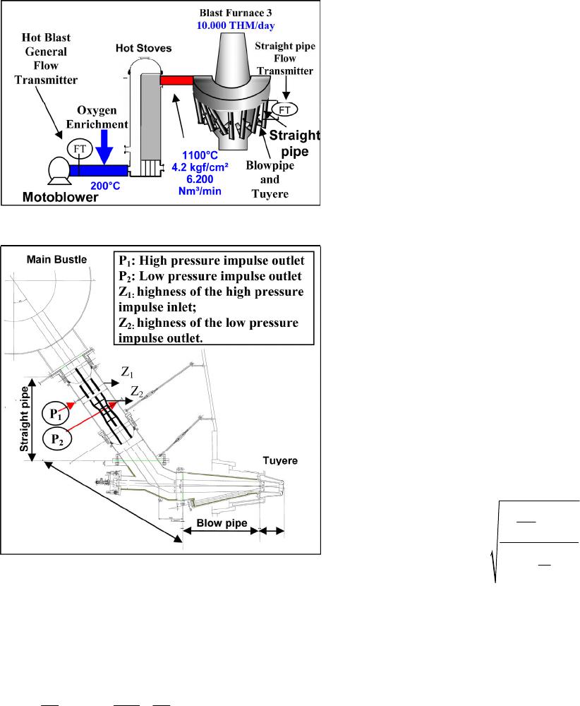
Figure 7. Flow measurement iinfluence by the d waste.
ment is affected in percentage (DV%-Equation (9)) ac-
cording to the d waste as it approaches to the D diameter.
11. Evaluation of the Results
The main results were the calculations memorial and the
gauging of hot blast flow measurement system through
the tuyeres seeking to have safety interlocks demanded
by the coal injection process.
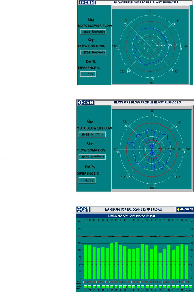
Another result of this work was the flow distribution
profiles in section of each blast furnace tuyeres illus-
trated in the graph screens of DCS shown in 4 and 5, as
well as a real time comparison model of the measurement
additions, with the general measurement coming from
motoblower plant.
In the BF3, the missed flow measurement propitiated
an interlock for the lances of pulverised coal injection.
This was verified by applying a new identification and
adjustment method, where the individual flow additions
of each tuyere’s transmitters were compared to the cold
air general flow transmitter coming from the motoblower
system.
In the BF2, there were many alarms for high flow in
the straight tubes, due to many stopped tuyeres, the flow
had its value increased in each one of the remaining
straight tubes, easily achieving its interlock values for
high flow, that’s why the flow scale was increased from
160 to 200 m3/min, these values are found in Table 1.
12. Discussion
Motta [1] had the aim of developing the differential
pressure flow measurement for blast furnace using basic
parameters and variables. However, there was no method
for the validation. In this work, the analogical flow trans-
mitters were implemented and the obtained results were
more precise, in the fittings, for considering the real con-
ditions of the blow, as density of the blown air flow,
pressure, temperature, viscosity of the air, friction of the
air with the Venturi tube and the inertia.
The only difficulty is to keep the system since the re-
striction of the straight pipe wastes along the time, and
therefore the straight pipe must be changed every two or
three years to maintain its operation and the essential
safety interlocks.
13. Conclusions
The modelling for the calculation of the straight tubes
flow transmitters differential pressure measurement in
the Blast Furnace was made with large precision taking
into account all possible variables.
The validation method has got a new approach and the
safety PCI interlocks are the high lights of this innovat-
ing work. The blast air and feed back of the flow meas-
urement model were compared to each other.
The reference is to change the straight pipe during the
Blast Furnace stop. Besides, the refractory Venturi waste
can be evaluated along the years and it is used to pro-
gram the change of the most wasted straight pipe.
The new developments showed that the SPV with
double refractory type, the methods and formulas to cal-
culate the P parameter, the validation method and the
new safety PCI interlocks were created due to a lot of
mess and trouble caused by explosions in the past tense.
Those explosions and down legs full of coals have ne-
ver been noticed again, since the implementation of the
actions described here along the last five years.
All the methods and safety interlocks implementations
performed here in this article can be reproduced and im-
plemented in any blast furnace with coal injection system
around the world. The cost of the implementation is
worthy when compared to the new blast furnace safety
operational conditions for PCI.
REFERENCES
[1] M. et Alli, “Modeling of the Measurement of Flow Meas-
urement of the Flow of Hot Air in Straight Tube of Blast
Furnace,” 39th Seminar of Reduction of Ore of Iron and
Raw Materials, Ouro Preto, 22-26 November 2009, pp.
1-10.
[2] G. J. Delmée, “Manual de Mediçao de Vazão,” Editora
Edgard Blücher Ltda, São Paulo, 1983.
[3] E. C. Bortoni and Z. Souza, “Instrumentation for Energy
and Industrial Systems,” Editora Novo Mundo Ltda, Ita-
jubá, 2006.
[4] L. Siglüeri and A. Nishinori, “Controls Automatic of In-
dustrial Processes,” Edgard Blücher Ltda, São Paulo,
1992.
[5] A. Johansson and A. Medvedev, “Detection of Incipient
Clogging in Pulverised Coal Injection Lines,” IEEE Trans-
actions on Industry Applications, Vol. 36, No. 3, 2000, pp.
877-883. http://dx.doi.org/10.1109/28.845065
[6] W. Birk, A. Johansson and A. Medvedev, “Model-Based
Goes to Fine Coal Injection Plant,” IEEE Control Systems
Magazine, Vol. 19, No. 1, 1997, pp. 33-43.
http://dx.doi.org/10.1109/37.745765