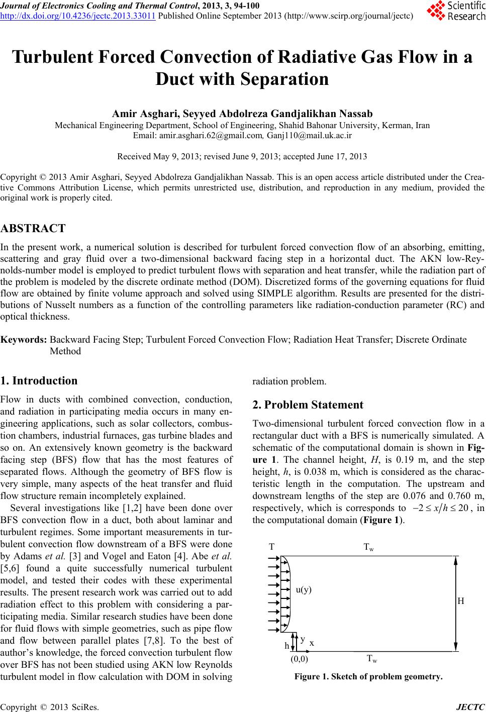
 Journal of Electronics Cooling and Thermal Control, 2013, 3, 94-100 http://dx.doi.org/10.4236/jectc.2013.33011 Published Online September 2013 (http://www.scirp.org/journal/jectc) Turbulent Forced Convection of Radiative Gas Flow in a Duct with Separation Amir Asghari, Seyyed Abdolreza Gandjalikhan Nassab Mechanical Engineering Department, School of Engineering, Shahid Bahonar University, Kerman, Iran Email: amir.asghari.62@gmail.com, Ganj110@mail.uk.ac.ir Received May 9, 2013; revised June 9, 2013; accepted June 17, 2013 Copyright © 2013 Amir Asghari, Seyyed Abdolreza Gandjalikhan Nassab. This is an open access article distributed under the Crea- tive Commons Attribution License, which permits unrestricted use, distribution, and reproduction in any medium, provided the original work is properly cited. ABSTRACT In the present work, a numerical solution is described for turbulent forced convection flow of an absorbing, emitting, scattering and gray fluid over a two-dimensional backward facing step in a horizontal duct. The AKN low-Rey- nolds-number model is employed to predict turbulent flows with separation and heat transfer, while the radiation part of the problem is modeled by the discrete ordinate method (DOM). Discretized forms of the governing equations for fluid flow are obtained by finite volume approach and solved using SIMPLE algorithm. Results are presented for the distri- butions of Nusselt numbers as a function of the controlling parameters like radiation-conduction parameter (RC) and optical thickness. Keywords: Backward Facing Step; Turbulent Forced Convection Flow; Radiation Heat Transfer; Discrete Ordinate Method 1. Introduction Flow in ducts with combined convection, conduction, and radiation in participating media occurs in many en- gineering applications, such as solar collectors, combus- tion chambers, industrial furnaces, gas turbine blades and so on. An extensively known geometry is the backward facing step (BFS) flow that has the most features of separated flows. Although the geometry of BFS flow is very simple, many aspects of the heat transfer and fluid flow structure remain incompletely explained. Several investigations like [1,2] have been done over BFS convection flow in a duct, both about laminar and turbulent regimes. Some important measurements in tur- bulent convection flow downstream of a BFS were done by Adams et al. [3] and Vogel and Eaton [4]. Abe et al. [5,6] found a quite successfully numerical turbulent model, and tested their codes with these experimental results. The present research work was carried out to add radiation effect to this problem with considering a par- ticipating media. Similar research studies have been done for fluid flows with simple geometries, such as pipe flow and flow between parallel plates [7,8]. To the best of author’s knowledge, the forced convection turbulent flow over BFS has not been studied using AKN low Reynolds turbulent model in flow calculation with DOM in so lving radiation pr o bl em. 2. Problem Statement Two-dimensional turbulent forced convection flow in a rectangular duct with a BFS is numerically simulated. A schematic of the computational domain is shown in Fig- ure 1. The channel height, H, is 0.19 m, and the step height, h, is 0.038 m, which is considered as the charac- teristic length in the computation. The upstream and downstream lengths of the step are 0.076 and 0.760 m, respectively, which is corresponds to 22xh 0, in the computational domain (Figure 1). x y H h 0 0 u(y) T T w T Figure 1. Sketch of problem geometry. C opyright © 2013 SciRes. JECTC  A. ASGHARI, S. A. GANDJALIKHAN NA SSAB 95 In the test case related to numerical validation, the fluid physical properties are treated as constants and ev a l u a t ed f o r air at the in let te mpera ture o f T0 = 20˚C (i.e. density (ρ) is 3 1.205 kgm, molecular dynamic viscos- ity (µ) is 5 1.78210kg ms , specific heat (Cp) is 1005 J/(kg˚C) and Prandtl number (Pr) is 0.71). The channel expansion ratio is 1.25, with a Reynolds number of 28,000 based on the centerline velocity at the inlet sec- tion (u0 = 10.86 m/s) and step height. 2.1. Basic Equations For predicting turbulent flow and heat transfer in sepa- rating and reattaching flows, quite successfully AKN model that introduced by Abe et al. [5,6], was selected for this study. The governing equations for BFS flow, which are con- sidered to be 2-D, steady, incompressible and turbulent are the equation of continuity, the Reynolds averaged Navier-Stokes equation, the equations of the turbulent kinetic energy k for the velocity field and its dissipation rate ε, the energy equation, and the equations of the tur- bulent kinetic energy t2 for the thermal field and its dis- sipation rate εt that can be written as follows: Continuity: 0 i i u x (1) Two-equation model for velocity field: 1 ˆj ii ij ij ji u Du u puu Dtx xxx (2) ˆ Dt ti ij jkj j u Dkk uu xx x (3) 2 12 ˆ Dt ti ij jj j u DCuu Cf xxk xk (4) with 2 3 j i ij uu t ij ji u uk xx (5) Two-equation model for thermal field (note that molecu- lar viscosity is negligible): ˆr j jp DTT ut Dt xxC q (6) 22 2 11 2 2 2211 22 2 ˆtttt PP j jj ti t PP ijDDDD j DT Cf ut Dt xxx t u Cf uuCfCf kx t t k (8) with jt T ut (9) where 2 tCfk (10) 2 tCfk (11) 22 34 5 1exp1 exp 14 200 t t R y fR 2 t ˆ t jhj j Dtt T ut xx x Dt (7) (12) 22 1exp 10.3exp 3.1 6.5 t R y f (13) 34 12 32 12 2 23 1exp1exp 14 14 d m R R f CR Pr k yPr y (14) 2 exp 200 t d R f (15) 2 11 2 1 1exp;1.0 DP P D y ff f A (16) 2 22 2 D 22 11exp DD Cf y fCA (17) 2 210.3exp 6.5 t R f (18) 22tkRt (19) 2 t Rk (20) 14 n y y (21) In the above equations, ij uu is the Reynolds stress component and ut is the turbulent heat flux. Also, the constants parameters in the governing equations are given in Table 1. At the inlet duct section, the fluid flow consists a uni- form temperature profile (T0 = 600 K). Also, the walls considered isotherm with temperature of 750 K. Copyright © 2013 SciRes. JECTC  A. ASGHARI, S. A. GANDJALIKHAN NA SSAB Copyright © 2013 SciRes. JECTC 96 nts appearing in the governing equations. Table 1. Model consta C k m C 1 C 2 C C 1 C 2 C h 1 C 2 C 1 2D 0.09 1.4 1.40.5 1.5 1.9 0.1 2 0.9 1.6 1.61.9 0.6 1 5.7 .2. Gas Radiation Modeling with radiation effect, d (22) where, and are position and direction of the ra- 2 In presence of participating media ** * 2 ˆ ˆ ,, , ii 00 0 *0 23 0 00 2 *2 * * 0 22 00 ** 00 **** 44 , ,, ,, ,,, ,, ,,, besides the convective and conductive terms in the en- ergy equation, the radiative term r q is also exist that can be calculated as [9]: 4 4, ra b II qrrs ii w tn tn ww ij j ij j w tt r rtt ww TT kh kT Pr TT uu hu y t ty h TTTT uuu t uuu t uh TTh I ITT q q (25) For example, non-dimensional form of Equation (6) is: xu pt xu pt hu hu u r in s diation tensity ,Irs. To obtain the radiation inten- sity field and then the term r q, we should solve the radiative transfer equation (Rfirstly, that for an ab- sorbing, emitting and scattering gray medium can be written as: TE) 4 , ,, 4 s ab I II I srs rsrrs ss,d (23) in which is incoming and is scattered directions ** 4 12 * 41 1 2 1DTT ut ˆ 1RC 41 j jj n ii i Pe Dt x x T s uni s phand , ss is the scattering ase function which is equaty for isotropic scattering media. The nu- merical procedure in solving RTE (that is the DOM) was given in detail by the second author in his previous work [10]. By this method, heat flux may also be determined from surface energy balance, as: l to 0 i wwbwiiw i IwI ns qnrrr ns (24) The boundary conditions for the radiative problem are treated as diffusely walls with constant emissivity of 0.8 w . In addition, the inlet and outlet sections are d as pseudo-black walls at their temperatures equal to fluid temperature in inlet and outlet sections, respectively [11]. The local total N considere usselt number along the duct walls is defined as tt wb Nuq hTT where t q represents the sum of ce heat flus such that onvective and radiativ xe tcr r qqqTyq . Therefore, the function tctive Nusselt number, Nuc, and local radiative Nusselt number, Nur. Nu is the sum of local conve 2.3. Non-Dimensional Forms of the Governing In tution of governing equations, the Equations he numerical sol following dimensionless parameters are used to obtain the non-dimensional forms of the equations: w Pe (26) Two physical quantities of interest in heat transfer study are the mean bulk temperature and the convective and radiative Nusselt numbers which are defined by: 1dTu y *01 0 d b T uy (27) * ** 12 ** ** 0 RC 1 tcr y wb wb T Nu Nu Nuq TTyTT r (28) 3. Numerical Procedure lved numerically by the velocity and temperature s of 430(x) × 28 The governing equations are so CFD techniques to obtain the fields. Discrete procedure utilizes the method of line-by- line in conjunction with finite volumes that coded into a computer program in FORTRAN and solved b y SIMPLE algorithm of Pat a nkar an d Sp al di ng [1 2] . Based on the grid-independent study, several grid dis- tributions were performed and the grid 0(y) downstream of the step were selected for the nu- merical analysis, while using denser mesh of 470(x) × 330(y) resulted in less than 2% difference in the value of maximum total Nusselt number on the bottom wall (Ta- ble 2). Non-uniformly structured with highly concen-  A. ASGHARI, S. A. GANDJALIKHAN NA SSAB 97 trated close to the wall surfaces and near the step corners and the reattachment zone, were used in order to ensure the accuracy of numerical solution. Since, in the DOM, different numbers of discrete direc- tions can be chosen during SN approximation, the results ob accuracy of convective heat benchmark problem was selec- tained by the S4, S8 and S12 approximations were com- pared and there was a sm all difference, less than 2% e rro r, between S8 and S12 approximations. Therefore, S8 appro- ximation has been used i n su b sequent cal cul at i ons. 4. Code Validation In order to validate the transfer computations, a ted. It deals to a turbulent convection flow over a BFS in a duct in which the bottom wall downstream of the step is supplied with a uniform heat flux 2 270Wm w q, while other walls are treated as adiabatic surface. So pre- dicted Stanton number profile on th- tained by two-equation turbulence model compared with experimental data [4] and a numerical data [13] with as- sumption of constant turbulent Prandtl number, where exhibited in Figure 2. It can be seen that the two-equa- tion turbulence model prediction is in better agreement with experiment. It should be noted that as the radiating effect of the g as flow is neglected i e bottom wall ob n that test case, the gas flow is consid- er = 0.5, = 15. ed non-participating media in the computation of Fig- ure 2, where the validation of combined conductive- radiative heat transfer results was given by the second author in his previo us work [10]. Table 2. Grid independence study, RC = 25, Grid size 390 × 230 430 × 280 470 × 330 max t Nu 71.98 77.51 78.87 5. Results and Discussions Figure 2. Comparison of the Stanton number with the ex- perimental and theoretical results. The numerical results are presented for a turbulent sepa- low of a radiating gas rated and reattached convection f over a 2-D BFS in a horizontal duct. The results repre- sent how well the energy transfer from the wall to the g as as the fluid flow passes through the channel. In order to show the variations of Nusselt numbers (Nuc,r,t) along the bottom wall, Figure 3 is plotted with considering the effect of RC parameter, which shows the relative importance of the radiation mechanism com- pared with its conduction counterpart. Figure 3(a) illus- trates the distribution of Nur along the bottom wall. It is seen that as the distance increases from the step corner, (a) (b) Figure 3. Effect of RC on the Nu distribution along the bot tom wall, = 15, = 0.5: (a) number; (b Convective and total Nusselters. - ) Radiative Nusselt numb Copyright © 2013 SciRes. JECTC  A. ASGHARI, S. A. GANDJALIKHAN NA SSAB 98 the value of radiative heat flux and consequently radia- tive Nusselt number increases sharply to its maximum value, which is due to a decreases in bottom wall incident radiative heat flux incoming from the stepped surface. After the maximum point, Nur decreases and approaches to a constant value as the distance continues to increase in the stream wise direction. Besides, Figure 3(a) shows that the Nur increases by increasing in RC, which is due to the increases in bottom wall’s outgoing radiative heat flux. The distributions of both conductive and total Nusselt numbers along the bottom wall are presented in Figure 3(b) at different values of the RC parameter. The varia- tion of Nuc shows an increasing trend in the recirculation zone after the step corner, such that the maximum value of Nuc occurs at the reattachment point, after which the Nuc approaches to a constant value far from the step lo- cation. Also, it is seen from Figure 3(b) that the Nuc de- creases by increasing in RC. This is due to this fact that under the effective presence of radiation heat transfer at high value of RC, the temperature field inside the flow domain becomes more uniform. Consequently, the value of temperature gradient inside the flow domain decreases that causes a decrease in the value of convection coeffi- cient on the bottom wall. The distribution of total Nu sselt number is also shown in Figure 3(b). It is seen that Nut and Nuc have similar trend but Figure 3(b) illustrates that Nut increases with increasing in RC. One can easily ana- lyze this trend by considering the definition of Nut, and its relation with Nuc and Nur. The effect of optical thickness on Nuc and Nut are shown in Figure 4. It is seen from Figure 4(a) that the effect of on Nu is simila cr to that of RC parameter (Figure 3). But if one focuses on Figure 4(b) in which the effect of on Nut is presented, it can be found that by increasing in from 0.1 to 0.5 (optically thin me- dia), Nut has increasing trend. But with more increase in from 0.5 to higher values, the trend has been reversed. This is the reason why the curve for 1 lies between the curves for 0.1 and 0.5 . It should be noted that similar results have been reported by Tsai and ozisic [14]. 6. Conclusion Numerical simulation of 2-D turbulen t forced convection S has been studied, including thermal in a duct with a BF radiation. The effects of RC parameter and optical thick- ness on the Nusselt numbers distribution along with the bottom wall downstream of the channel step were pre- sented. Numerical results show that by increasing in RC parameter, the Nuc decreases whereas the Nut increases along the bottom wall. Also, numerical results revealed that by increasing the optical thickness, the Nuc decreases (a) (b) Figure 4. Effect of optical thickness on the Nusselt number distribution along the bottom wall, RC = 25, = 0.5: (a) Convective Nusselt number;Total Nusselt number. op- cal thickness from τ to greater values, the Nu has a [1] B. F. Armaly, F. Durst, J. C. F. Pereira and B. Schnung, “Experimental tigation of Back- ward-Facing S Fluid Mechanics, (b) monotonically, but the Nut increases to a critical value for the optical thickness. Such that by increasing the ti critical t decreasing trend. REFERENCES and Theoretical Inves tep Flow,” Journal of Vol. 127, 1983, pp. 473-496. doi:10.1017/S0022112083002839 [2] B. F. Armaly, A. Li and J. H. Nie, “Measurements in Three-Dimensional Separated Flow,” International Jour- Copyright © 2013 SciRes. JECTC  A. ASGHARI, S. A. GANDJALIKHAN NA SSAB Copyright © 2013 SciRes. JECTC 99 46, No. 19, 2003, ppnal of Heat Mass Transfer, Vol. . 3573-3582. doi:10.1016/S0017-9310(03)00153-4 [3] E. W. Adams, J. P. Johnston and J. K. Eaton, “Experi- ments on the Structure of Turbulent Reattaching Flow,” Technical Report MD-43, Thermo-Sciences Div p,” ASME Journal of Heat Transfer ision, Department of Mechanical Engineering, Stanford Univer- sity, Stanford, 1984. [4] J. C. Vogel and J. K. Eaton, “Combined Heat Transfer and Fluid Dynamic Measurements Downstream of a Backward-Facing Ste, Vol. 107, No. 4, 1985, pp. 922-929. doi:10.1115/1.3247522 [5] K. Abe, T. Kondoh, and Y. Nagano, “A New Turbulence Model for Predicting Fluid Flow an Separating and Reattachd Heat Transfer in ing Flows—I. Flow Field Calcu- lations,” International Journal of Heat Mass Transfer, Vol. 37, No. 1, 1994, pp. 139-151. doi:10.1016/0017-9310(94)90168-6 [6] K. Abe, T. Kondoh and Y. Nagano, “A New Turbulence Model for Predicting Fluid Flow and Heat Tr Separating and Reattaching Flows— ansfer in II. Thermal Field Calculations,” International Journal of Heat Mass Trans- fer, Vol. 38, No. 8, 1995, pp. 1467-1481. doi:10.1016/0017-9310(94)00252-Q [7] H. Bouali and A. Mezrhab, “Combined Radiative and Convective Heat Transfer in a Divided Ch national Journal of Numerical Met annel,” Inter- hods for Heat and Fluid Flow, Vol. 16, No. 1, 2006, pp. 84-106. doi:10.1108/09615530610636973 [8] D. G. Barhaghi and L. Davidson, “Large-Eddy Simula- tion of Mixed Convection-Radiation Heat Tran Vertical Channel,” International sfer in a Journal of Heat and Mass Transfer, Vol. 52, No. 17-18, 2009, pp. 3918-3928. doi:10.1016/j.ijheatmasstransfer.2009.03.031 [9] M. F. Modest, “Radiative Heat Transfer,” Academic Pre ss, San Diego, 2003. [10] A. B. Ansari and S. A. Gandjalikhan Nassab, “Study of Laminar Forced Convection of Radiating Gas over an In- clined Backward Facing Step under Bleeding Condition Using the Blocked-Off Method,” ASME Journal of Heat Transfer, Vol. 133, No. 7, 2011, pp. 3573-3582. doi:10.1115/1.4003607 [11] M. S. Ko, “Numerical Simulation of Three-Dime Combined Convective nsional Heat Transfer in Rectangular nd Momentum Transfer in Three- Channels,” Ph.D. Dissertation, Texas A&M University, College Station, 2007. [12] S. V. Patankar and D. B. Spalding, “A Calculation Pro- cedure for Heat, Mass a Dimensional Parabolic Flows,” International Journal of Heat Mass Transfer, Vol. 15, No. 10, 1972, pp. 1787- 1806. doi:10.1016/0017-9310(72)90054-3 [13] Y. T. Chen, J. H. Nie, B. F. Armaly and H. T. Hsieh, “Turbulent Separated Convection Flow Adjacent to Back- ward-Facing Step—Effects of Step Height,” International Journal of Heat and Mass Transfer, Vol. 49, No. 19-20, 2006, pp. 3670-3680. doi:10.1016/j.ijheatmasstransfer.2006.02.024 [14] J. R. Tsai and M. N. Ozisik, “Radiation and Lam ced Convection of Non-Newtonian Fluid ininar For- a Circular Tube,” International Journal of Heat and Fluid Flow, Vol. 10, No. 4, 1989, pp. 361-365. doi:10.1016/0142-727X(89)90027-1  A. ASGHARI, S. A. GANDJALIKHAN NA SSAB 100 Nomenclature ER: expansion ratio, H/(H-h) I: radiation intensity Ib: black body radiation intensity k: turbulent kinetic energy, 2 ii uu p: pressure Pe: Peclet number, Re Pr Pr, Prt: molecular and turbulent Prandtl number r Re: Reynolds number, q: radiative heat flux vector 0 uh RC: radiation-conduction parameter, 3 w Th St: Stanton number, 00 w pw q Cu TT T,t: mean temperature and temperature fluctuation ˆ t: time ui: general notation for mean velocity components 12 ,uuuv u: velocity fluctuation i : general notation for coordinate directions 12 , xx y n y: normal distance to the wall surface Greek Symbols ,t : molecular and eddy diffusivity : extinction coefficient ij : Kronecker delta : dissipation rate of turbulent kinetic energy, ij ij ux ux t : dissipation rate of 22t, j tx tx w : wall emissivity : thermal conductivity : solid angle ,t : molecular kinematic and eddy visco sities : Stefan Boltsman’s constant, 5.67 ×10⁻⁸ W/m2K4 : scattering coefficient a : absorption coefficient : albedo coefficient, 1a : optical thickness, h 12 , : dimensionless temperature parameters 1002 0 , ww TT TTT Subscripts b: bulk c: convective r: radiative w: wall Superscript *: dimensionless symbol Copyright © 2013 SciRes. JECTC
|