 Journal of Sensor Technology, 2013, 3, 84-93 http://dx.doi.org/10.4236/jst.2013.33014 Published Online September 2013 (http://www.scirp.org/journal/jst) An Electrochemical Nitrite Sensor Based on a Multilayer Film of Polyoxometalate Yosra Sahraoui1,2, Sana Chaliaa3, Abderrazak Maaref1, Amor Haddad3, Nicole Jaffrezic-Renault2* 1Laboratory of Interfaces and Advanced Materials, Faculty of Sciences of Monastir, Monastir, Tunisia 2University of Lyon, Institute of Analytical Chemistry, Villeurbanne, France 3 Laboratory of Materials and Crystallochemistry, Superior Institute of Applied Science and Technology, Mahdia, Tunisia Email: *nicole.jaffrezic@univ-lyon1.fr Received July 8, 2013; revised August 8, 2013; accepted August 15, 2013 Copyright © 2013 Yosra Sahraoui et al. This is an open access article distributed under the Creative Commons Attribution License, which permits unrestricted use, distribution, and reproduction in any medium, provided the original work is properly cited. ABSTRACT In this work, we have developed an electrochemical sensor for nitrite detection, based on a polyoxometalate (POM) namely mono-lacunary keggin anion [SiW11O39]8− cited as (SiW11). Electrochemical characterization of SiW11 shows two-step reduction processes, with formal potentials of −0.5 V (I) and −0.68 V (II). Oppositely charged polyelectrolyte (poly (allylamine hydrochloride) (PAH)) and (SiW11) were assembled alternately to modify glassy carbon electrode. The electrochemical behavior of the modified electrode was studied in detail using cyclic voltammetry (CV). The re- sults showed that SiW11/PAH/GC electrode present good electrocatalytic activity for the reduction of nitrite. The sensor showed a dynamic range from 100 µM to 3.6 mM of nitrite and no interference from other classical anions. Experimen- tal factors that affect electron-transfer rate in these films, such as pH effect and layers number, were systematically analyzed. Keywords: Nitrite Sensor; Polyoxometalate; Mono-Lacunary Keggin Anion; Layer by Layer Assembly Process 1. Introduction The presence of nitrite in groundwater and atmosphere is an essential precursor in the formation of nitrosamines, many of which have been proven to be powerful carcino- gens [1-3]. The increase in nitrite concentration in the blood causes a decrease in oxygen transport by the blood causing methemoglobinemia, better known as the “blue baby syndrome” reaction of nitrite with Fe (II) forming hemoglobin to methemoglobin, HbFe (III) [4]. For these reasons, determination of nitrite has received consider- able attention. Many methods have been developed for nitrite determination including spectrophotometry [5], chromatography [6] and electrochemical methods [7-12], which are advantageous over the other methods in terms of cost and time. Electrochemical determination of nitrite ion requires a large over potential at almost all electrode surfaces [13-15]. The better way to achieve nitrite detection at low overpotentials is the use of mediators confined at the electrode surface. Over the years, numbers of modifica- tion procedures have been reported for the construction of modified electrodes [17-19]. Many studies reported the capability of hexacyanoferrate anion complex [20] for the homogeneous electrocatalytic reduction of nitrite and employed this catalytic reduction method for deter- mination of it in real samples. They demonstrated also, that the poly-ortho-toluidine can catalyze the nitrite re- duction as heterogeneous catalysis [21]. Polyoxometalates (POMs), a large family of charged, nanoscopic inorganic clusters, are attractive materials for electrode modification because of their reversible redox behavior, good chemical stability and electronic conduc- tivity [22]. These compounds are also resistant to oxida- tive degradation due to the fact that their fundamental elements are in their higher oxidation state [23-26]. These properties make them very attractive in many fields such as electrochemistry, catalysis and for bio- medicinal tasks [23,27-30]. There is a different type of polyoxometalates [27], and in our study Keggin-type POMs are specifically used. They *Corresponding author. C opyright © 2013 SciRes. JST  Y. SAHRAOUI ET AL. 85 display a quite well-known structural motif that is com- posed of a tetrahedrally coordinated central hetero atom surrounded by four W3O13 groups (triads) that are con- nected in a corner-sharing fashion via oxygen atoms [31, 32]. Lacunary Keggin structures [SiW11O39]8− (SiW11) used in this study, are derived from the parent Keggin type by the removal of specific WO6 moieties, followed by an optional rotation of the remaining WO6 octahedra [33,34]. As a consequence, (SiW11) is characterized by the presence of more terminal oxygen atoms, which give them more negative charge than other POMs structure. Layer-by-layer (LBL) self-assembly has proved to be a promising method for the fabrication of ultrathin films. It is based on the alternate adsorption on the substrate sur- face of oppositely charged species from dilute solutions and film formation is attributed primarily to electrostatic interaction and Van der Waals forces. It provides thick- ness control at the nanometer level, which can be easily adapted for automated fabrication. It is applicable to any substrate shape and also permits co-assembly with dif- ferent functional components [35]. Owing to these ad- vantages, the layer-by-layer approach has been utilized to fabricate POM-containing multilayer film consisting of synthetized or natural polyelectrolytes. Several studies used the parent Keggin silicotungstate [α-SiW12O40]4− as the anion and, for example, polyaniline [36], chitosan [37] or poly (diallyldimethylammonium chloride) [38] as the counter cation source. There are only few examples of the use of lacunary Keggin polyoxotungtate anions in films prepared by the layer-by-layer self-assembly method [39]. It has been reported that metal-substituted Keggin silicotungstate could be used as mediator for the elec- troreduction of nitrite [40]. In this paper, we show the capability of SiW11 anion immobilized by electrodeposi- tion and LBL methods, for the electrocatalytic reduction of nitrite and this property is applied for the first time for the design of a selective amperometric sensor for nitrite. 2. Experimental 2.1. Materials Ultrapure milliQ water with a resistance of 18.2 MΏ cm was used for all experiments. P-phenylenediamine (PPD), poly (allylamine hydrochloride) (PAH) (MW 15,000), sulfuric acid (H2SO4), sodium nitrite (NaNO2), the fol- lowing product were purchased from commercial sources and used without further purification from Sigma-Al- drich. Gold nanoparticles 20 nm diameter, stabilized suspension in 0.1 M PBS were commercial products from Sigma-Aldrich. Solution of redox probe (1.0 mM) was prepared dissolving the appropriate amounts of 34 6 Fe CN in 1 M KCl. K8 [-SiW11O39]·13H2O was synthesized as the litera- ture described [41]. Briefly, a solution of 4 M HCl was added over 10 min, to a mix of sodium meta-silicate so- lution (2.23 g, 10 mM) (Solution A), and sodium tung- state (36.29 g, 110 mM). Solid Potassium Chloride (20 g) was then added to the solution with gentle stirring, after 15 min the precipitate was collected by filtration. Purification was achieved by dissolving the product in water (200 mL) and insoluble material being removed by filtration on a fine frit. The salt was precipitated again by addition of solid potassium chloride (10 g) before being collected by filtration, washed with 2 M potassium chloride and air dried to give K8[-SiW11O39]· 13H2O as a white powder (13.86 g, 33.6%). 2.2. Apparatus Electrochemical measurements were carried out using a potentiostat-galvanostat VOLTALAB 40 PGZ/301, 746 VA Trace Analyzer (Metrohm) equipped with a 747 VA Stand. A three-electrode system was used, the side arms contained Ag/AgCl (sat. KCl) reference electrode and a platinum counter electrode with a surface area of ap- proximately 1 cm2. The working electrode was a SiW11 modified glassy carbon electrode (3 mm diameter, sur- face area: 7 mm2). Prior to coating, the GCE was condi- tioned by a polishing/cleaning procedure. The GCE was successively polished with 1.0, 0.3, and 0.05 µm α-Al2O3 paste and then rinsed with ultra-pure water to remove any residual alumina and finally sonicated for 5 min in an ultrasonic bath and dried under a stream of pure nitrogen. SEM characterization of the films was performed us- ing a Quanta TM 250 microscope (FEI) in degraded pres- sure mode; no gold coating was required. The infrared spectra were recorded as KBr pellets, in the 4000 - 400 cm−1 range on a Nicolet 470 FT-IR spectrophotometer. Dynamic light scattering (Zetasizer Nano-ZS, Malvern Instruments) was used for the determination of the zeta potential. 2.3. Preparation of the Modified Electrodes SiW11 modification of GC electrode was performed by using electrodeposition and layer-by-layer methods for the building of multilayers, by alternately dipping the desired substrate in PAH and SiW11 solutions, in cyclic mode [42]. Figure 1 displays a schematic representation of the different layers of the SiW11/LBL film. The GC electrode was first placed in 2 mM PPD solu- tion and the potential was repeatedly scanned. PPD was electropolymerized onto GCE surface by amine cation radical formation. The oxidation peak gradually dimin- ishes and is almost absent after the 6th cycle, this obser- vation indicates the formation of a coating on the elec- trode surface (cf. Figure 2). Copyright © 2013 SciRes. JST  Y. SAHRAOUI ET AL. 86 PPD I SiW 11 II GC AH Re eat I, III III Figure 1. Schematic representation of 5-SiW11/PAH/PPD/ GCE multilayer films. Figure 2. Cyclic voltammograms on a freshly polished GCE in 2 mM PPD solution, for the (1) first, (2) second, (3) third, (5) fifth and (6) sixth cycles, at a scan rate: 100 mV/s. The polyPPD.GC electrode was then placed in 2 mM (SiW11) solution, 0.1 M H2SO4 and at the same time a cyclic potential sweep was conducted in the potential range 0.8 V to −0.8 V at a scan rate of 100 mV/s−1, for 25 cycles. In this way, a SiW11 monolayer was deposited on the surface of polyPPD/GCE [42]. Then, the resulting electrode (SiW11/polyPPD/GC) was transferred to 2 mM PAH (pH = 3) for 15 min, for resulting in one layer of positive charge. This procedure (SiW11/PAH) was re- peated until obtaining 5 layers of SiW11. 3. Results and Discussion 3.1. Characterization of SiW11 in Solution The prepared compound was characterized by infrared spectroscopy, and cyclic voltammetry in acidic aqueous solution, because Keggin type and its derivative are un- stable in neutral and basic solutions. The cyclic voltam- mogram becomes ill-defined and peak current much smaller, such an observation has been reported by Cheng et al. [43] on Keggin-type polyoxometallates. The FT-IR spectra of the lacunary keggin silicotungstate in KBr pressed pellets are presented in (Figure 3). The attributions of FT-IR spectra exhibits characteris- tic bands at 3424.0, 1634 (OH); 988.4 as(Si-O); 945.4 cm−1 (W = O); 882.1, 733.8, 624.7 as (W-O-W); 532.2 (O-Si-O) cm−1. The silicotungstate vibrational spectrum was in agreement with previously reported analysis [44]. The redox behavior of SiW11 in solution (conditions: 2 mM SiW11 in 0.1 M H2SO4 solution) was studied by cy- clic voltammetry and polarography. The dissolved SiW11 shows that the CV curve exhibits two pairs of successive redox waves with cathodic peaks located respectively EpcI = −0.5 V (I) and EpcII = −0.68 V (II), and peak separation potentials (∆Ep) of 65 and 44 mV respectively, in the potential range from +0.8 V to −0.8 V (Figure 4(a)). This result is consistent with that in literature [45]. These redox waves correspond to the reduction of the tungsten centers within the SiW11 (WVI → WV). The re- duction of heteropolyanions is accompanied by protona- tion, therefore, the pH of solution has a great effect on the electrochemical behavior of heteropolyanions. The pH effect on the electrochemical behavior of the Figure 3. The FT-IR spectra of the K8[-SiW11O39]·13H2O. Figure 4. Cyclic voltammogras of: (a) 2 mM SiW11 in 0.1 m M H2SO4 solution and (b) multilayer film of 5-SiW11/PAH/ PPD/GCE at a scan rate: 100 mV/s. Copyright © 2013 SciRes. JST  Y. SAHRAOUI ET AL. 87 soluble SiW11 was studied by polarography. The peak (step 2) time they are gr potentials for both redox couples shift to the more nega- tive direction with increasing pH. Plots of Ep of the two successive redox waves (step I and step II) versus pH for the (SiW11) (Figure 1S), show good linearity in the pH range from 0.8 to 4.3. Slopes in this pH range are −69, −85 mV pH step (I) and (II), respectively, which are close to the theoretical value of −60 mV per pH for the 2e−/2H+ redox process [46]. The above results may indi- cate the two overall redox process of (SiW11) in acidic solution as follows: (step 1) VI 8VVI 8 11 3922939 SiWO2e 2HHSiWWO VVI8 VVI8 229 39229 39 HW WO2e2HHSiW WO 3.2. Characterization of the Modified Electrode 3.2.1. Electrochemical Characterization Define abbreviations and acronyms the first used in the text, even after they have been defined in the abstract. Abbreviations such as IEEE, SI, MKS, CGS, sc, dc, and rms do not have to be defined. Do not use abbre- viations in the title or heads unless they are unavoidable. Through the attachment of polyPPD containing NH2 oup to the GCE, the modified electrode (poly) PPD/ GCE was positively charged at least up to pH 6.1 [47]. The PPD-modified GCE with an amido-terminated mo- nolayer can be used as a charge-rich precursor to assem- ble oppositely charged species by layer-by-layer electro- static interaction [48]. The adsorption of a layer of SiW11 is evidenced through the behavior of the modified elec- trode in presence of 34 Fe CN redox probe (cf 6 b). The presen H with SiW11 was ev f Si Figure 5, curves a andce of the negative layer of SiW11 increases ΔEp by more than 100 mV and decreases, mainly the cathodic peak, which is due to the electrostatic repulsion of the probe. The electrostatic interaction of PA idenced by using gold nanoparticles initially covered with a citrate monolayer, a layer on PAH being adsorbed on their surface, their zeta potential was found to be +44 mV. After adsorption of SiW11, the zeta potential became equal to −1.1 mV, then showing the neutralization of the positive charge by successful adsorption of SiW11. Figure 5 shows that with increasing the number o W11 layers from one to five, the peak maxima of 34 Fe CN redox probe decrease, transducing a 6 decrease of charge t11 ransfer through the SiW LBL film. This phenomenon can be due to the increase of the elec- trostatic repulsion between 34 Fe CN and the 6 BL film. more negatively charged SiW11 L 34 6 Fe CN Figure 5. Cyclic voltammograms of (1 mM th (PPD/PAH/ Figure 4 shows a comparison between the cyclic vol- ta mical stability of the SiW11/PAH/PPD/ G 3.2.2. SEM Characterization of SiW11/polyPPD Film - , 1 M KCl), at modified electrodes wiSiW11) n for n = 1, 3 and 5. mmogram of the soluble and immobilized SiW11 in LBL films of 5-SiW11 layers. Immobilized in LBL film, SiW11 displays a close similar electrochemical behavior to that of soluble SiW11. These observations demonstrate that the electrochemical behavior of the SiW11 anion is maintained in the multilayer films [40]. Nevertheless, EpcI was shifted to 0.454 V and EpcII to 0.722 V versus Ag/AgCl. The redox peaks were broadered and ∆EpI was found to be around 150 mV whereas ∆EpII was around 70 mV. The broadening can be related to the large cou- lombic repulsion between the negative sites of highly- charged polyanions in the same layer, as in [37]. The decrease of reversibility could be attributed to the de- crease of charge transfer rate through the poorly conduc- tive PPD layer. The electroche C electrode was investigated in 0.1 M H2SO4 solution at a scan rate of 100 mV s−1. After 300 cycles, the catho- dic peak current (peak II) still remains about at 93% of the initial value. These results indicate that the SiW11/ PAH/polyPPD/GC electrode present a good stability. In order to observe the SiW11/polyPPD film in an accu rate way, the film was electrodeposited onto gold elec- trode, by the method described above. Near the border, we can clearly see that the majority of the electrode sur- face is covered by the PPD film and there is no appear- ance of dendrite structure (Figure 6(a)), so we can say that the morphologies seen at the polyPPD/gold electrode surface are similar to those at the polyPPD/GC surface. The successful immobilization of SiW11 in the electrode surface is confirmed by the energy-dispersive X-ray (ED- X) analyses (Figure 7), showing the presence of W and Copyright © 2013 SciRes. JST 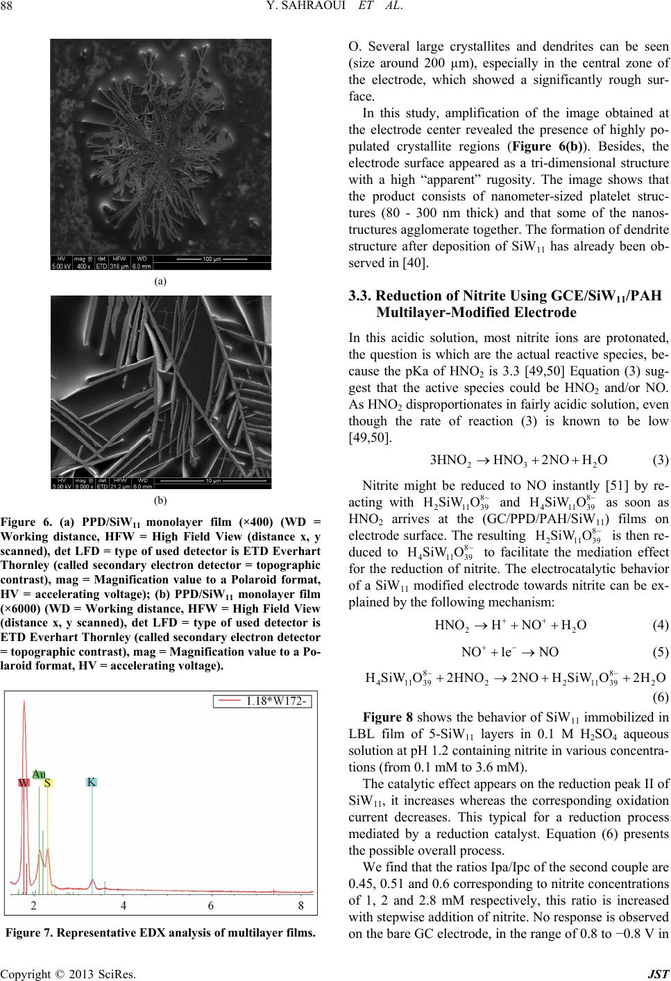 Y. SAHRAOUI ET AL. 88 (a) (b) Figure 6. (a) PPD/SiW11 monolayer film (×400) (WD = Working distance, HFW = High Field View (distance x, y scanned), det LFD = type of used detector is ETD Everhart Thornley (called secondary electron detector = topographic contrast), mag = Magnification value to a Polaroid format, HV = accelerating voltage); (b) PPD/SiW11 monolayer film (×6000) (WD = Working distance, HFW = High Field View (distance x, y scanned), det LFD = type of used detector is ETD Everhart Thornley (called secondary electron detector = topographic contrast), mag = Magnification value to a Po- laroid format, HV = accelerating voltage). Figure 7. Representative EDX analysis of multilayer films. O his study, amplification of the image obtained at th 3.3. Reduction of Nitrite Using GCE/SiW/PAH In throtonated, 2 (3) Nitrite might be reduced to NO instantly [5 ac . Several large crystallites and dendrites can be seen (size around 200 µm), especially in the central zone of the electrode, which showed a significantly rough sur- face. In t e electrode center revealed the presence of highly po- pulated crystallite regions (Figure 6(b)). Besides, the electrode surface appeared as a tri-dimensional structure with a high “apparent” rugosity. The image shows that the product consists of nanometer-sized platelet struc- tures (80 - 300 nm thick) and that some of the nanos- tructures agglomerate together. The formation of dendrite structure after deposition of SiW11 has already been ob- served in [40]. 11 Multilayer-Modified Electrode is acidic solution, most nitrite ions are p the question is which are the actual reactive species, be- cause the pKa of HNO2 is 3.3 [49,50] Equation (3) sug- gest that the active species could be HNO2 and/or NO. As HNO2 disproportionates in fairly acidic solution, even though the rate of reaction (3) is known to be low [49,50]. 23 3HNOHNO2NOHO 1] by re- ting with 8 21139 HSiW O and 8 41139 HSiW O as soon as HNO2 arriveC/PPD1) films on electrode surface. The resulting 8 21139 HSiW O is then re- duced to 8 41139 HSiWO s at the (G/PAH/SiW1 to facilitation effect for the redrite. The electrocatalytic behavior of a SiW11 modified electrode towards nitrite can be ex- plained by the following mechanism: HNOHNO H ate the medi uction of nit 2O 2 (4) O1e NO Figure 8 shows the behavior of SiW11 immobilized LB the reduction peak II of Si Ipc of the second couple are 0. (5) 88 411392211392 HSiWO2HNO2NOHSiWO2HO (6) in L film of 5-SiW11 layers in 0.1 M H2SO4 aqueous solution at pH 1.2 containing nitrite in various concentra- tions (from 0.1 mM to 3.6 mM). The catalytic effect appears on W11, it increases whereas the corresponding oxidation current decreases. This typical for a reduction process mediated by a reduction catalyst. Equation (6) presents the possible overall process. We find that the ratios Ipa/ 45, 0.51 and 0.6 corresponding to nitrite concentrations of 1, 2 and 2.8 mM respectively, this ratio is increased with stepwise addition of nitrite. No response is observed on the bare GC electrode, in the range of 0.8 to −0.8 V in Copyright © 2013 SciRes. JST  Y. SAHRAOUI ET AL. 89 Figure 8. Cyclic voltammograms showing the catalytic ac .1 M HSO4 solutions containing 0.4 mM and 0.6 mM 3.4. Effect of the Number of Layers on the In orect of the number of layers on c re 3.5. Calibration Curve and Reproducibility line- 3.6. Life Time e nitrite sensor was investigated over a - tivity of SiW11/LBL film (5-SiW11 layers) at different nitrite concentrations: 0, 1, 2 and 2.8 mmol/L. 02 of 2 NO , as shown in (Figure 8(e)). Nitrite Reduction der to confirm the eff the electrochemical properties, the electrochemical be- haviors of SiW11-modified electrode were investigated. With increasing number of SiW11 layers, the catalyti duction of nitrite increases. For example, the electro- catalytic current observed with 5- SiW11 layers is higher than the current observed with 2- SiW11 layers in the presence of 0.1 mM of nitrite. The response of the modi- fied electrode toward nitrite is practically constant when number of layers is high than 5 (Figure 9). The catalytic peak maximum at potential −0.68 V is arly dependent on the nitrite concentration, in the range 0.1 mM - 3.6 mM, with correlation coefficient of 0.9991, as shown in Figure 10. The reproducibility of the nitrite sensor was studied by using three different sensors, the cathodic peak current corresponding to 2.8 mM of nitrite still remains about 93%. The stability of th period of 75 days. The sensor was stored under air at room temperature and the current response to 3 mM of nitrite injection in 0.1 M H2SO4 pH 1.2 was checked at regular intervals. No significant change (< 10%) was observed within this period of time. The stability of this sensor can be attributed to the large amount of SiW11 which is deposited on the surface of the electrode. Figure 9. The relationship between peak currents (EpcII) versus number of layers (2 to 10 layers). Figure 10. Calibration curveLinear relationship between the catalytic current and nitricentrations at −0.6 V vs. wed that SiW11 modified electrode perties towards nitrate molecular monstrate that the second redox cou- can act as a mediator for the catalytic : te con Ag/AgCl. Electrolyte (0.1 M H2SO4), scan rate 100 mV/s. 3.7. Interferences Our experiments sho has no catalytic pro (Figure 2.A.S). The response of SiW11 modified elec- trode was also tested toward other ions such as phosphate (Figure 2.B.S) and perchlorate (Figure 2.C.S), with con- centrations between 2 mM and 6 mM. No significant in- crease in the current was observed. Hence, this proves the selective determination of nitrite because it eliminates the major interferences such as nitrate. 4. Conclusions In this study, we de ple of SiW anion 11 reduction of nitrite in aqueous solution with H2SO4 con- centration (0.1 M). The electrochemical behavior of the Copyright © 2013 SciRes. JST  Y. SAHRAOUI ET AL. 90 modified electrode was studied using cyclic voltammetry. Catalytic reduction of nitrite can be employed as a new method for determination of nitrite in real sample such as weak liquor existing in the wood and paper industry. This method is simple, low-cost and precise for routine control and can be carried out directly without any sepa- ration or pretreatment due to the selective electrocatalytic reduction of nitrite. The catalytic reduction peak current showed a linear dependent on the nitrite concentration and a linear cali- br EGIDE through UTIQ by PHC Maghreb program REFERENCES [1] I. A. Wolf andtrates, Nitrites, and Nitrosamines,” . 4043, 1972, pp ation curve was obtained. Further studies for using this nitrite sensor in real samples are under investigation. 5. Acknowledgements This work was supported by program No. 09G 1128 and UE No 27960UG. A. E. Wasserman, “Ni Science, Vol. 177, No . 15-19. doi:10.1126/science.177.4043.15 [2] W. Lijinsky and S. S. Epstein, “Nitrosamines as Environ- mental Carcinogens,” Nature, Vol. 225, No. 5227, 1970, pp. 21-23. doi:10.1038/225021a0 [3] A. J. Dunham. R. M. Barkley and R. E. Sievers, “Aque- ous Nitrite Ion Determination by Selective Reduction and Gas-Phase Nitric-Oxide Chemiluminescence,” Analytical Chemistry, Vol. 67, No. 1, 1995, pp. 220-224. doi:10.1021/ac00097a033 [4] V. Y. Titov and Y. M. Petrenko, “Proposed M of Nitrite-Induced Methemo ech globinemia,” Biochemistry on Analy- anism (Moscow), Vol. 70, No. 4, 2005, pp. 473-483. [5] G. M. Greenway, S. J. Haswell and P. H. Petsul, “The Development of an On-Chip Micro-Flow Injecti sis of Nitrate with a Cadmium Redactor,” Analytica Chimica Acta, Vol. 387, No. 1, 1999, pp. 1-10. doi:10.1016/S0003-2670(99)00047-1 [6] M. I. H. Helaleh and T. J. Korenaga, “Chroma Method for Simultaneous Determinat tographic ion of Nitrate and Nitrite in Human Salivia,” Journal of Chromatography B: Biomedical Sciences and Applications, Vol. 744, No. 2, 2000, pp. 433-437. doi:10.1016/S0378-4347(00)00264-4 [7] W. J. R. Santos, A. L. Sousa, R. C. S. Luz, F. S. Damos, L. T. Kubota, A. A. Tanaka and S. M. C. N. Tanaka, “Amperometric Sensor for Nitrite Using a Glassy Carbon Electrode Modified with Alternating Layers of Iron(III) Tetra-(N-methyl-4-pyridyl)-porphyrin and Cobalt(II) Tet- rasulfonated Phthalocyanine,” Talanta, Vol. 70, No. 3, 2006, pp. 588-594. doi:10.1016/j.talanta.2006.01.023 [8] J. E. Newbry and M. P. L. de Haddad, “Amperometric Determination of Nitrite by Oxidation at a Glassy Carbon Electrode,” Analyst, Vol. 110, No. 1, 1985, pp. 81-82. doi:10.1039/an9851000081 [9] M. Trojanowiez, W. Matuszewski and B. Szostek, “Sim lataneous Determination of u- Nitrite and Nitrate in Water Using Flow-Injection Biamperometry,” Analytica Chimica Acta, Vol. 261, No. 1-2, 1992, pp. 391-398. doi:10.1016/0003-2670(92)80218-V [10] Z. H. Wen and T. F. Kang, “Determinatio Using Sensors Based on Nickel Phth n of Nitrite alocyanine Polymer Modified Electrodes,” Talanta, Vol. 62, No. 2, 2004, pp. 351-355. doi:10.1016/j.talanta.2003.08.003 [11] P. Tau and T. Nyokong, “Electrocatalytic Activity of Arylthio Tetra-Substituted Oxotitanium(IV) Phthalocya- nines towards the Oxidation of Nitrite,” Electrochimica Acta, Vol. 52, No. 13, 2007, pp. 4547-4553. doi:10.1016/j.electacta.2006.12.059 [12] J. Obirai and T. Nyokong, “Electrochemical a Properties of Chromium Tetra Am nd Catalytic inophthalocyanine,” Journal of Electroanalytical Chemistry, Vol. 573, No. 1, 2004, pp. 77-85. doi:10.1016/S0022-0728(04)00341-9 [13] A. Y. Chamsi and A. G. Fogg, “Oxidative Flow Injection Amperometric Determination of Nitrite at an Electro- chemically Pre-Treated Glassy Carbon Electrode,” Ana- lyst, Vol. 113, No. 11, 1988, pp. 1723-1727. doi:10.1039/an9881301723 [14] Z. Zhao and X. Cai, “Determination of Trace Catalytic Polarography in Fe Nitrite by rrous Iron Thiocyanate Me- dium,” Journal of Electroanalytical Chemistry and Inter- facial Electrochemistry, Vol. 252, No. 2, 1988, pp. 361- 370. doi:10.1016/0022-0728(88)80222-5 [15] J. N. Barisci and G. G. Wallace, “Detection of Nitrite Using Electrodes Modified with an Electrodeposited Ru- thenium-Containing Polymer,” Analytical Letters, Vol. 24, No. 11, 1991, pp. 2059-2073. doi:10.1080/00032719108053033 [16] S. A. Wring and J. P. Hart, “C bon-Based Electrodes and Their A hemically Modified, Car- pplication as Electro- chemical Sensors for the Analysis of Biologically Impor- tant Compounds,” Analyst, Vol. 117, No. 8, 1992, pp. 1215-1229. doi:10.1039/an9921701215 [17] J. A. Cox, M. E. Tess and T. E. Cummings, “Electro- chemistry of Organized Monolayers of Thiols and Re- ed Electrochemi- lated Molecules on Electrodes,” Reviews in Analytical Chemistry, Vol. 15, 1996, pp. 173-223. [18] J. P. Hart and S. A. Wring, “Recent Developments in the Design and Application of Screen-Print cal Sensors for Biomedical, Environmental and Industrial Analyses,” TrAC Trends in Analytical Chemistry, Vol. 16, No. 2, 1997, pp. 89-103. doi:10.1016/S0165-9936(96)00097-0 [19] J. Wang, P. V. A. Pamidi rived Cobalt Phthalocyanine-Dispersed and C. Parrado, “Sol-Gel-De- Carbon Composite Electrodes for Electrocatalysis and Amperometric Flow Detection,” Electroanalysis, Vol. 9, No. 12, 1997, pp. 908-911. doi:10.1002/elan.1140091208 [20] R. Ojani, J. B. Raoof and E. Zarei, “Electrocatalytic Re- duction of Nitrite Using Ferricyanide; Application for Its Simple and Selective Determination,” Electrochimica Acta, Vol. 52, No. 3, 2006, pp. 753-759. doi:10.1016/j.electacta.2006.06.005 [21] R. Ojani, J. B. Raoof and E. Zarei, “Poly Modified Carbon Paste Electrode: A (ortho-toluidine) Sensor for Electro- Copyright © 2013 SciRes. JST  Y. SAHRAOUI ET AL. 91 catalytic Reduction of Nitrite,” Electroanalysis, Vol. 20, No. 4, 2008, pp. 379-385. doi:10.1002/elan.200704045 [22] K. Jiang, H. Zhang, C. Shannon and W. Zhan, “Prepara- tion and Characterization of Polyoxometalate/Protein Ul- trathin Films Grown on Electrode Surfaces Using Layer- by-Layer Assembly,” Langmuir, Vol. 24, No. 7, 2008, pp. 3584-3589. doi:10.1021/la704015j [23] M. T. Pope, “Heteropoly and Isopoly Oxometalates,” Springer Verlag, New York, 1983, pp. 23-27. doi:10.1007/978-3-662-12004-0 [24] M. T. Pope, In: G. Wilkinson, R. D. Gillard McCleverty, Eds., Comprehensiv and J. A. e Coordination Chemis- and a Trac- try, Pergamon Press, 1987, Vol. 3, pp 1023. [25] L. C. W. Baker and D. C. Glick, “Present General Status of Understanding of Heteropoly Electrolytes ing of Some Major Highlights in the History of Their Elucidation,” Chemical Reviews, Vol. 98, No. 1, 1998, pp. 3-50. doi:10.1021/cr960392l [26] C. L. Hill, “Polyoxometalates,” Chemical Reviews, Vol. 98, No. 1, 1998, pp. 1-2. doi:10.1021/cr960395y iews [27] M. Sadakane and E. Steckhan, “Electrochemistry and Electrocatalysis of Polyoxometalates,” Chemical Rev, Vol. 98, No. 1, 1998, pp. 219-237. doi:10.1021/cr960403a [28] C. L. Hill and C. M. Prosser-McCa Catalysis by Transition Meta rtha, “Homogeneous l Oxygen Anion Clusters,” Coordination Chemistry Reviews, Vol. 143, 1995, pp. 407-455. doi:10.1016/0010-8545(95)01141-B [29] B. Keita and L. Nadjo, “Polyoxometalate-Based Homo- geneous Catalysis of Electrode Reactions: Recent Achie- vements,” Journal of Molecular Catalysis A: Chemica l, Vol. 262, No. 1-2, 2007, pp. 190-215. doi:10.1016/j.molcata.2006.08.066 [30] R. Neumann, “Chapter 8,” In J. E. Back Oxidation Methods, Wiley-VCH, W vall, Ed., Modern einheim, 2004, pp d,” Nature, Vol. 132, 1933, pp. 351-351. . 223-251. [31] J. F. Keggin, “Structure of the Crystals of 12-Phospho- tungstic Aci doi:10.1038/132351a0 [32] J. F. Keggin, “The Structure and Formula of 12-Pho photungstic Acid,” Pr s- oceedings of the Royal Society s London, Series A, Vol. 144, No. 851, 1934, pp. 75-100. [33] B. Keita, A. Belhouari, L. Nadjo and R. Contant, “Elec- trocatalysis by Polyoxometalate/Vbpolymer System: Reduction of Nitrite and Nitric Oxide,” Journal of Elec- troanalytical Chemistry, Vol. 381, No. 1-2, 1995, pp. 243-250. doi:10.1016/0022-0728(94)03710-K [34] U. Kortz, N. K. Al-Kassem, M. G. Savelieff, N. A. Al Kadi and M. Sadakane, “Synthesis and Characterization of Copper, Zinc, Manganese, and Cobalt-Substituted Dimeric Heteropolyanions, [(α-XW9O33)2M3(H2O)3]n− (n = 12, X = AsIII, SbIII, M = Cu2+, Zn2+; n = 10, X = SeIV, TeIV, M = Cu2+) and [(αAsW9O33)2WO(H2O)M2 (H2O)2]10− (M = Zn2+, Mn2+, Co2+),” Inorganic Chemistry, Vol. 40, No. 18, 2001, pp. 4742-4749. doi:10.1021/ic0101477 [35] G. Decher and J. B. Schenoff, “Multila Wiley VCH, Weinheim, yer Thin Films,” 2003, 524p. on a Keggin-Type [36] Y. Wang, C. Guo, Y. Chen, C. Hu and W. Yu, “Self- Assembled Multilayer Films Based Polyoxometalate and Polyaniline,” Journal of Colloid and Interface Science, Vol. 264, No. 1, 2003, pp. 176-183. doi:10.1016/S0021-9797(03)00392-8 [37] Y. Feng, Z. Han, J. Peng, J. Lu, B. Xue, L. Li, H. Ma an E. Wang, “Fabrication and Characteriz d ation of Multilayer Films Based on Keggin-Type Polyoxometalate and Chi- tosan,” Materials Letters, Vol. 60, No. 13-14, 2006, pp. 1588-1593. doi:10.1016/j.matlet.2005.11.069 [38] S. Li, E. Wang, C. Tian, B. Mao, Y. Song, C. Wang and L. Xu, “In Situ Fabrication of Amino Acid-Polyoxometalate Nanoparticle Functionalized Ultrathin Films and Relevant Electrochemical Property Study,” Materials Research Bulletin, Vol. 43, No. 11, 2008, pp. 2880-2886. doi:10.1016/j.materresbull.2007.12.012 [39] D. M. Fernandes, H. M. Carapuça, C. M. A. Bret M. V. Cavaleiro, “Electrochemical Be t and A. haviour of Self- Assembly Multilayer Films Based on Iron-Substituted α-Keggin Polyoxotungstates,” Thin Solid Films, Vol. 518, No. 21, 2010, pp. 5881-5888. doi:10.1016/j.tsf.2010.05.065 [40] D. M. Fernandes, S. M. N. Sim A. M. V. Cavaleiro, “Function oes, H. M. Carapuca and alisation of Glassy Carbon Electrodes with Deposited Tetrabutylammonium Micro- crystalline Salts of Lacunary and Metal-Substituted α- Keggin-Polyoxosilicotungstates,” Electrochimica Acta, Vol. 53, No. 22, 2008, pp. 6580-6588. doi:10.1016/j.electacta.2008.04.071 [41] A. Téazéa, G. Hervéa, R. G. Finke and D. K. β-, and γ-Dodecatungstosilicic Acid Lyon, “α-, s: Isomers and Re- lated Lacunary Compounds,” In: Inorganic Syntheses, John Wiley & Sons, New York, 1990, pp. 85-96. doi:10.1002/9780470132586.ch16 [42] D. U. Jinyan, L. V. Guiqin, H. U. Changwen and Huaqiang, “Layer-by-Layer Assem W. U. bly of Silicotungstate Multilayer Films Modified on Glassy Carbon Electrode and Their Electrochemical Behaviors,” Annali di Chimica, Vol. 97, No. 5-6, 2007, pp. 313-320. doi:10.1002/adic.200790017 [43] L. Cheng, H. Seen, J. Liu and S. Dong Behavior of a Series of Undec , “Electrochemical atungstozincates Monosub- stituted by First-Row Transition Metals, ZnW11M(H2O) O39 n– (M = Cr, Mn, Fe, Co, Ni, Cu or Zn),” Journal of the Chemical Society, Dalton Transactions, No. 15, 1999, pp. 2619-2626. doi:10.1039/a901846h [44] C. Rocchiccioli-Deltcheff, M. Fournier, R. Franck and R. Thouvenot, “Vibrational Investigations of Polyoxometa- lates. 2. Evidence for Anion-Anion Interactions in Mo- lybdenum(VI) and Tungsten(VI) Compounds Related to the Keggin Structure,” Inorganic Chemistry, Vol. 22, No. 2, 1983, pp. 207-216. doi:10.1021/ic00144a006 [45] D. M. Fernandes, C. M. A. Brett and A. M. V. Cavaleiro, “Layer-By-Layer Self-Assembly And Electrocatalytic Properties Of Poly(Ethylenimine)-Silicotungstate Multi- layer Composite Films,” Journal of Solid State Electro- chemistry, Vol. 15, No. 4, 2011, pp. 811-819. doi:10.1007/s10008-010-1154-1 [46] I. M. Mbomekalle, B. Keita, Y. W. Lu, L. Nadjo, R. Can- Copyright © 2013 SciRes. JST  Y. SAHRAOUI ET AL. Copyright © 2013 SciRes. JST 92 d El awson-Type Tungstoar- tant, N. Belai and M. T. Pope, “Synthesis an chemistry of the Monolacunary D ectro- senate [H4AsW17O61]11− and Some First-Row Transition- Metal Ion Derivatives,” European Journal of Inorganic Chemistry, Vol. 2004, No. 20, 2004, pp. 4132-4139. doi:10.1002/ejic.200400186 [47] S. D. Chambers, M. T. McDermott and C. A. Lucy, “Co- valently Modified Graphitic Carbon-Based Station Phases for Anion Chromato ary graphy,” Analyst, Vol. 134, No. 11, 2009, pp. 2273-2280. doi:10.1039/b911988d [48] J. Liu, L. Cheng, B. Liu and S. Dong, “Covalent Modifi- cation of a Glassy Carbon Surface by 4-Aminobenzoic Acid and Its Application in Fabrication of a Polyoxome- talates-Consisting Monolayer and Multilayer Films,” Langmuir, Vol. 16, No. 19, 2000, pp. 7471-7476. doi:10.1021/la9913506 [49] B. Keita, F. Girard, L. Nadjo, R. Contant, R. Belghiche and M. Abbessi, “Cyclic Voltammetric Evidence of Fa- cilitation of the Reduction of Nitrite by the Presence of Molybdenum in Fe- or Cu-Substituted Heteropolytung- states,” Journal of Electroanalytical Chemistry, Vol. 508, No. 1-2, 2001, pp. 70-80. doi:10.1016/S0022-0728(01)00516-2 [50] S. Dong, X. Xi and M. Tian, “Study lytic Reduction of Nitrite with Si of the Electrocata- licotungstic Heter- opolyanion,” Journal of Electroanalytical Chemistry, Vol. 385, No. 2, 1995, pp. 227-233. doi:10.1016/0022-0728(94)03770-4 [51] L. Ruhlmann and G. Genet, “W Tetrameric Complexes {K28H8[P2W ells-Dawson-Derived Ti O60.5]4} Elec- 15 3 trochemical Behaviour and Electrocatalytic Reduction of Nitrite and of Nitric Oxide,” Journal of Electroanalytical Chemistry, Vol. 568, 2004, pp. 315-321. doi:10.1016/j.jelechem.2004.02.020 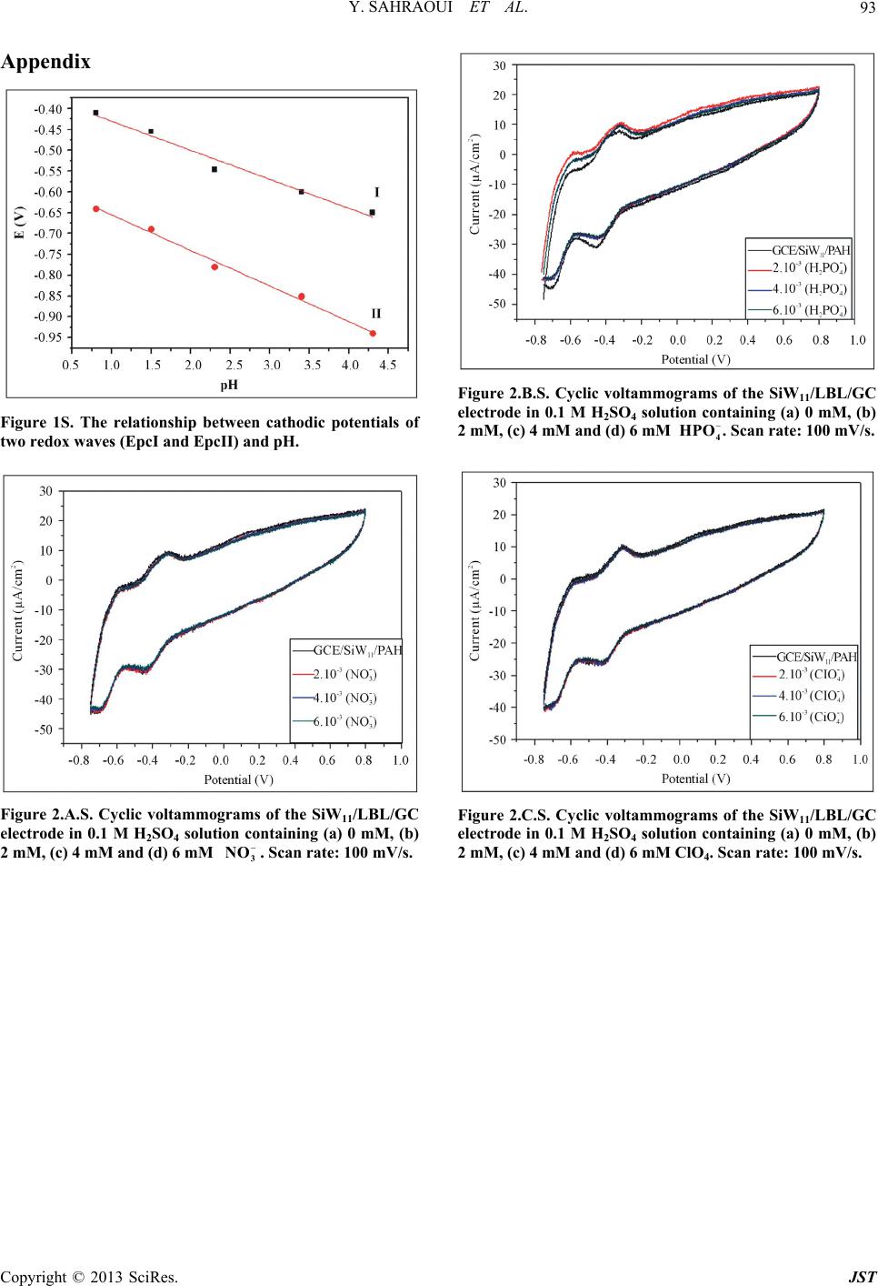 Y. SAHRAOUI ET AL. 93 Appendix Figure 1S. The relationship between cathodic potentials of two redox waves (EpcI and EpcII) and pH. Figure 2.A.S. Cyclic voltammograms of the SiW11/LBL/GC electrode in 0.1 M H2SO4 solution containing (a) 0 mM, (b) 2 mM, (c) 4 mM and (d) 6 mMScan rate: 100 mV/s. 3 NO . Figure 2.B.S. Cyclic voltammograms of the SiW11/LBL/GC electrode in 0.1 M H2SO4 solution containing (a) 0 mM, (b) 2 mM, (c) 4 mM and (d) 6 mMScan rate: 100 mV/s. 4 HPO . Figure 2.C.S. Cyclic voltammograms of the SiW11/LBL/GC electrode in 0.1 M H2SO4 solution containing (a) 0 mM, (b) 2 mM, (c) 4 mM and (d) 6 mM4. Scan rate: 100 mV/s. ClO Copyright © 2013 SciRes. JST
|