Journal of Cancer Therapy, 2013, 4, 1251-1255
http://dx.doi.org/10.4236/jct.2013.47147 Published Online September 2013 (http://www.scirp.org/journal/jct)
1251
Clinical and Dosimetric Implications of Air Gaps between
Bolus and Skin Surface during Radiation Therapy
Yousaf Khan1, J. Eduardo Villarreal-Barajas1, Mona Udowicz1, Richie Sinha1, Wazir Muhammad2,
Ahmed N. Abbasi3, Amjad Hussain3*
1Department of Radiation Oncology, Tom Baker Cancer Centre, Calgary, Canada; 2Institute of Nuclear Medicine, Oncology and
Radiotherapy, Abbottabad, Pakistan; 3Radiation Oncology, Department of Oncology, Aga Khan University Hospital, Karachi, Paki-
stan.
Email: *amjadso_76@yahoo.com
Received July 13th, 2013; revised August 15th, 2013; accepted August 22nd, 2013
Copyright © 2013 Yousaf Khan et al. This is an open access article distributed under the Creative Commons Attribution License,
which permits unrestricted use, distribution, and reproduction in any medium, provided the original work is properly cited.
ABSTRACT
Purpose: The main objective of the study was to evaluate the effect of air gaps of 0 - 5.0 cm between bolus and skin for
1.0 cm Superflab bolus on surface dose (DSurf) and depth of maximum dose (dmax) in solid water and Rando® phantoms.
Methods: In this work, the effects of bolus to surface distance on DSurf and variation in dmax were analyzed in a solid
water phantom and in an anthropomorphic Rando® phantom for different field sizes, using Gafchromic® EBT films and
farmer chamber. Results: For field sizes of 5 × 5 cm2 the DSurf is significantly affected by increasing air gaps greater
than 5 mm. For field sizes larger than 10 × 10 cm2, DSurf is nearly the same for air gaps of 0 - 5.0 cm. For small fields
and 6 MV photon beam, dmax increases with increasing air gap, while for 10 MV beam and smaller field sizes (i.e. 5 × 5
and 10 × 10 cm2) the dmax first decreases and then increases with the air gaps. For both 3DCRT and IMRT plans on
Rando®, DSurf reduction is more prominent with increasing air gaps. Conclusion: For field sizes larger than 10 × 10 cm2
DSurf is largely unaffected by air gaps. However, smaller air gap results in shallower dmax for both 6 MV and 10 MV
photon beams at all fields sizes. Special consideration should be taken to reduce air gaps between bolus and skin for
field sizes smaller than 10 × 10 cm2 or when surface contour variations are greater or when the bolus covers small area
and at the border of the field.
Keywords: Bolus Distance; Skin Dose; IMRT; Dose Build-Up
1. Introduction
High energy photon beams typically have a lower dose at
skin (DSurf) than dose maximum (dmax ) at depth. This phe-
nomenon is known as “skin sparing” and estimated that
DSurf can be as low as 25% of the dose at dmax. For treat-
ing near surface tumors, bolus is placed on the surface in
order to increase DSurf. The effect of dose build-up is
more prominent in Mega Voltage (MV) photon beams
[1]. DSurf and dmax depend on photon beam energy, field
size, beam modification devices, SSD and angle of inci-
dence. These also depend on electron contamination from
the flattening filter, beam modifiers and air [2-4]. Accu-
rate measurement of DSurf doses in RT can provide valu-
able information for clinical use to avoid near surface
recurrences while at the same time limiting severe skin
toxicity [5,6].
Hsu et al. [7] reported no significant differences in
DSurf between IMRT and conventional radiotherapy tech-
niques. Lee et al. [8] found that the average increase of
DSurf was about 18% due to bolus effect of thermoplastic
shell. They also investigated that with thermoplastic shell
DSurf was 84% and 100% of the prescribed dose for par-
allel opposed (POP) and IMRT treatments respectively.
Higgins et al. [9] demonstrated that DSurf using POP,
tomotherapy and IMRT were 69%, 71% and 82% re-
spectively. Dogan and Glasgow [10] reported that DSurf
with 6MV photon beam IMRT were 8% and 6% lower
than those of the open field for zero and 750 gantry an-
gles respectively. Yokoyama et al. [11] stated that DSurf
with IMRT was 10% lower than the open field treatment.
Gray et al. [12] reported in their investigation of PDD
measurements that as the air gap increases from 1 to 15
cm, the dose reduces at the surface. In order to increase
DSurf in conventional total body irradiation (TBI) an
acrylic sheet of 1cm thickness is placed in front of the
*Corresponding author.
Copyright © 2013 SciRes. JCT
Clinical and Dosimetric Implications of Air Gaps between Bolus and Skin Surface during Radiation Therapy
1252
patient at 15 to 20 cm from the skin surface.
In photon beam radiation therapy such as breast and
chest wall it is desirable to predict the dose delivered to
skin, superficial nodes and/or any remnant in the surgical
scar of the patient for better treatment outcome. It is also
important to know any injury caused by radiation to the
skin. Many biological effects such as skin reactions are
correlated with basal cell layer damage. The basal cell
layer is located at about 0.07 mm depth and it is very
radio-sensitive.
Main objective of this study was to evaluate DSurf us-
ing a 1.0 cm Superflab bolus while introducing various
air gaps (0 cm - 5.0 cm). The following scenarios were
investigated:
1) Is zero-air gap absolutely necessary between skin
and bolus during real treatment delivery?
2) How depth of maximum dose (dmax) is affected by
the distance between bolus and skin surface.
As discussed earlier the DSurf also depends on the de-
livery technique in addition to bolus-surface distance
(BSD). Therefore doses were also measured and com-
pared for 3D-CRT and IMRT techniques. The goal of
these measurements was to demonstrate the impact of the
delivery technique on the DSurf in the presence of air gaps
in real clinical situations.
2. Materials and Methods
The effects of Superflab (Med-Tec, Orange, IA) bolus to
surface distance on the DSurf and variation in the dmax
were analyzed in a solid water phantom (Gammex RMI
Model 457, Middleton, WI) and in an anthropomorphic
Rando® phantom (The Phantom Laboratory, Salem, NY).
Rando® phantom was used to simulate head and neck
Intensity Modulated Radiotherapy (IMRT) and rectum
3D-CRT treatment techniques. All measurements were
performed on a 2100C (Varian, Palo Alto, CA) linear
accelerator (6 and 10 MV), equipped with 120-leaf Mil-
lennium MLC.
An exradin ionization chamber (Model A12) was used
for dose measurement in solid water phantom and to pro-
vide reference measurements for Gafchromic® EBT (In-
ternational Specialty Products, NJ, USA) film measure-
ments. Calibration of the Gafchromic® EBT film was per-
formed for a range of doses (5 to 300 cGy). Dose meas-
urement accuracy of the Gafchromic® EBT film was bet-
ter than ±2% with ±1.7 standard deviation. Each batch of
the Gafchromic® EBT films was calibrated separately.
2.1. Dose Measurements in Solid Water Phantom
Gafchromic® EBT film can potentially be used for DSurf
measurement. It is also considered a useful tool for ac-
curate dose measurement near the surface (i.e., within a
depth of a few mm), and for CNS junctions. Radiochro-
mic films were cut in two different shapes for surface (3
× 3 cm2) and depth (11 × 2 cm2) dose measurements.
Depth dose profiles were obtained with films sandwiched
vertically in slabs of solid water. For DSurf measurements
the square films were placed on top of the solid water
phantom at beam central axis. The separation between
the phantom surface and the bolus was adjusted with Sty-
rofoam sheets of 0.5, 1.0, 2.0, 3.0, 4.0 and 5.0 cm as
shown in Figure 1. Measurements with bolus placed
right on top of the water phantom (0 cm distance) and
without bolus were also performed. The source to phan-
tom surface distance was kept constant at 100 cm.
Doses (PDDs and DSurf) at the central axis with and
without bolus material were measured for 5 × 5 cm2, 10
× 10 cm2, 15 × 15 cm2 and 20 × 20 cm2 fields. All the
films were exposed to 100 cGy. The Gafchromic® EBT
film readings (optical densities) were converted to doses
using the calibration curve. All the dose profiles were
normalized to the maximum dose obtained with 0 cm
bolus to skin air gap.
2.2. DSurf Measurements on Rando® Phantom
IMRT and 3D-CRT plans were created using Eclipse on
a Rando® phantom: one for head and neck and another
for a rectum case with a prescribed dose of 200 cGy to
the reference point using 6 MV beam. The head and neck
IMRT plan was calculated for 5 fields. The rectum plan
was delivered with 4-field’s box technique.
Both the plans require the DSurf to be 95% of the pre-
Figure 1. Geometrical setup for surface and depth
dose measurements using solid water phantom.
Copyright © 2013 SciRes. JCT
Clinical and Dosimetric Implications of Air Gaps between Bolus and Skin Surface during Radiation Therapy 1253
scribed dose. Custom boluses were made for both plans.
Both plans were delivered without bolus and with bolus
at various distances from the skin.
The Rando® phantom was aligned using lasers on the
treatment couch according to the setup markings. DSurf
were measured for four locations (marked as 1, 2, 3 and 4
on the films) for the head and neck case and one position
for the rectum case as shown in Figure 2. Four strips
were placed at position 1, 2, 3, and 4 across the IMRT
fields from inferior to superior direction.
3. Results
To choose a suitable bolus for optimal Dsurf , three boluses
of different thicknesses (0.5 cm, 1.0 cm, and 1.5 cm)
were used with zero air gap from surface of the solid
water phantom. Dose measurements indicated that 1.0
cm bolus was the most effective in providing a consistent
high dose on the surface for 6 and 10 MV X-ray beams.
Although DSurf with 1.0 cm and 1.5 cm boluses were
nearly identical, the 1.0 cm bolus is more efficient due to
lesser attenuation. Figures 3(a)-(d) show measured DSurf
and dmax respectively in solid water phantom for field
sizes of 5 × 5 cm2, 10 × 10 cm2, 15 × 15 cm2 and 20 × 20
cm2, with BSDs of 0 cm, 0.5 cm, 1.0 cm, 2.0 cm, 3.0 cm,
4.0 cm, 5.0 cm, and also for corresponding unbolused
(open) beams.
Each curve is normalized to 100% at the reference
point on the surface of the solid water phantom with 0
cm BSD. An increase in surface dose is shown in these
figures when bolus is used. There is a negligible effect on
the DSurf with increasing the air gap for larger field sizes
compared to small fields. For a field size 5 × 5 cm2 DSurf
decreases by 34% and 30% with a 5 cm air gap for 6 and
10 MV photon beams respectively. A change in the dmax
is also observed with changing the air gap.
The dmax measured for open 6 MV and 10 MV photon
beams are 1.4 cm and 2.2 cm respectively. For smaller
field sizes such as 5 × 5 cm2 the relative DSurf is signifi-
cantly affected by air gaps greater than 0.5 cm. For larger
field sizes such as 10 × 10 cm2 and higher, relative DSurf
is nearly the same for air gaps of 0 cm - 5.0 cm. For
small field and 6 MV dmax increases with increase in air
gaps. For the 10 MV beam a similar trend like 6 MV
beam was observed for 15 × 15 cm2 and 20 × 20 cm2
field sizes, however for smaller fields (5 × 5 cm2 and 10
× 10 cm2) with increasing air gaps, dmax first decreases
and then increases as shown in Figure 3 ( d) .
Figures 4(a)-(d) show the Eclipse generated IMRT
(head & neck) and 3DCRT (4-fields-pelvis) treatment
plans with bolus placement and resultant dose distribu-
tions. These plans with air gaps of 0 cm to 5.0 cm were
delivered on a Varian Linac and measured with Gafchro-
mic® EBT films. Measured DSurf in Rando® phantom for
these plans using a 1 cm thick bolus is presented in Fig-
ures 5(a) and (b). For both the IMRT and 3DCRT plans
DSurf reduces with increasing air gaps by about 20%.
4. Discussion
A special consideration is needed when using a bolus for
dose buildup with smaller field sizes. It has been reported
by Kassaee et al. [13] that the spoiler should not be
placed at a distance less than 6 cm from skin surface in
order to avoid loss of skin sparing during TBI. It means
that if the air gap is less than 6 cm, the spoiler will act as
a bolus and the skin will receive a higher dose. Gray et al.
[12] reported that even when electronic equilibrium is
established in the material positioned before the air gap,
there is a secondary region of dose buildup beyond the
air gap to establish the electronic equilibrium when the
air gap is greater than 5 cm. They concluded that the air
gap greater than 5 cm should be avoided, because the
accuracy of Eclipse™ dose calculation beyond the sec-
ondary buildup region is out by ~2.5%. Based on these
findings, we selected our air gaps 0 to 5 cm for the cur-
rent study. Because bolus is only effective within a lim-
ited range of BSDs, positioning the bolus requires care
on the part of the radiation therapist for accurate dose
delivery to the surface.
Figures 3(a) and (b) show that, for a 1 cm water equi-
valent bolus placed above the phantom, an increase in the
air gap decreases the dose measured on the surface for
small field sizes (i.e., 5 × 5 cm2 and 10 × 10 cm2). On the
other hand for field sizes larger than 10 × 10 cm2 , the
DSurf is less affected by different air gaps. The reason for
lower DSurf for small field sizes are, less scatter contri-
bution from collimator and water phantom. Reduction in
the scatter from bolus with increasing air gap, reaching
the surface also reduces DSurf. This loss of scatter radia-
tion is mainly caused by the lateral spread of the scat-
tered radiation within the air gap and is directly propor-
tional to the size of the air gap for small field sizes. Small
fields are used clinically for some treatments such as
breast boost, and anal verge. In these scenarios the bolus
is placed almost in contact with the skin. For larger field
size such as chest wall the effect of gaps on the DSurf is
minimal as shown in Figure 2(b). In general, the contri-
Figure 2. Geometrical setup for DSurf measurements on
Rando® phantom.
Copyright © 2013 SciRes. JCT
Clinical and Dosimetric Implications of Air Gaps between Bolus and Skin Surface during Radiation Therapy
Copyright © 2013 SciRes. JCT
1254
Figure 3. (a) and (b) Relative DSurf curve for 6 and 10 MV beams 5 × 5 cm2, 10 × 10 cm2, 15 × 15 cm2 and 20 × 20 cm2 for 6
MV and 10 MV X-ray beams respectively, (c) and (d) Relation between dmax and BSD for field size 5 × 5 cm2, 10 × 10 cm2, 15
× 15 cm2 and 20 × 20 cm2 for 6 MV and 10 MV X-ray beams respectively.
Figure 4. (a), (b), (c) and (d), Head & Neck IMRT and
Pelvis 3DCRT location of bolus and skin rendering.
bution of electrons generated within the bolus increases
as the bolus gets closer to the phantom surface and as the
field size increases.
The findings shown in Figures 3(a)-(d) indicate that
both, field size and beam energy influence the dose
buildup and dmax. For 6 MV photon beam dmax is less
affected for all field sizes while for 10 MV photon beam
the relationship was only consistent for 15 × 15 cm2 and
20 × 20 cm2 filed sizes. For smaller field sizes the elec-
tronic equilibrium was established at greater depth than
for larger field sizes as shown in Figures 3(c) and (d).
The dmax is shifted deeper in water phantom for 10 MV
beam compared to 6 MV, as expected. The reason being
the range of secondary electrons in the air is larger for 10
MV than for 6 MV beam. Electrons from the bolus have
limited range and affect the dose only close to the surface
and up to dmax. In general DSurf due to contamination elec-
trons emanating from the bolus depends on the photon
beam energy, air gaps, field size and thickness of the
bolus.
The measured dose for IMRT and 3-DCRT treatments
show similar effects to those observed with solid water
phantom as shown in Figures 5(a) and (b). The reason
for higher dose to skin for IMRT plan is mainly due to
the presence of larger penumbra and overlapping fields.
5. Conclusion
The dose to the phantom surface in the presence of air
Clinical and Dosimetric Implications of Air Gaps between Bolus and Skin Surface during Radiation Therapy 1255
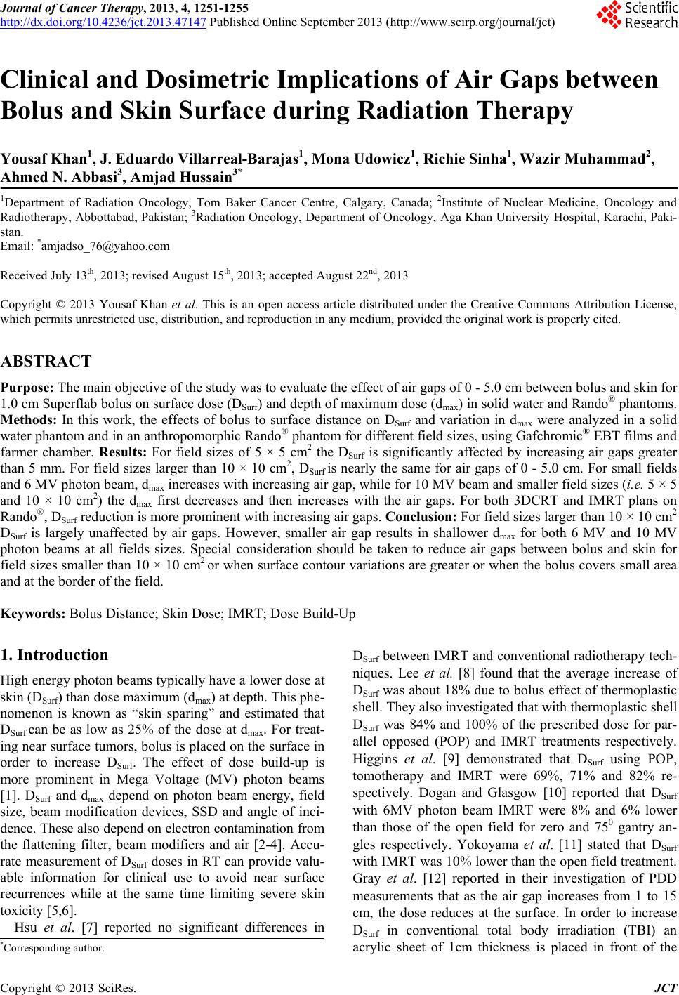
Figure 5. (a) Dose build up characteristics on skin surface for an IMRT 6 MV X-ray beam with 1cm of bolus material at 0 -
5.0 cm air gaps; (b) Reduction in dose caused by varying air gaps under 1 cm of bolus for a 4-fields box 3DCRT plan.
gaps with bolus is less affected for large field sizes such
as 15 × 15 cm
2 and greater. For larger field sizes DSurf
greater than 95% was observed for larger air gapes of 5
cm as well. For IMRT and 3DCRT plans delivered to
Rando®, 94% DSurf was observed for 1 cm air gap. Based
on our results, special consideration is required when
field sizes are smaller and surface contour variations are
greater or when the bolus cover small area and at the
border of the field. In general it is observed that the
closer the bolus to the phantom surface is, the shallower
the dmax is for both 6 MV and 10 MV photon beams and
all fields sizes. For both energies dmax is approximately
proportional to air gaps.
REFERENCES
[1] F. M. Khan, “The Physics of Radiation Therapy,” Lippin-
cott Williams & Wilkins, Philadelphia, 2010, p. 144.
[2] M. Stroka, J. Reguła and W. Łobodziec, “The Influence
of the Bolus-Surface Distance on the Dose Distribution in
the Build-Up Region,” Reports of Practical Oncology &
Radiotherapy, Vol. 15, No. 6, 2010, pp. 161-164.
doi:10.1016/j.rpor.2010.09.003
[3] K. I. Aneta, Ł. Włodzimierz, D. Marcin, N. Dorota and I.
Tomasz, “Dose Distribution Homogeneity in Two TBI
Techniques—Analysis of 208 Irradiated Patients Con-
ducted in Stanislaw Leszczynski Memorial Hospital, Ka-
towice,” Reports of Practical Oncology & Radiotherapy,
Vol. 17, No. 6, 2012, pp. 367-375.
doi:10.1016/j.rpor.2012.07.013
[4] J. B. Martin, C. Tsang and Y. Peter, “Effects on Skin
Dose from Unwanted Air Gaps under Bolus in Photon
Beam Radiotherapy,” Radiation Measurements, Vol. 32,
No. 3, 2000, pp. 201-204.
doi:10.1016/S1350-4487(99)00276-0
[5] S. H. Hsu, R. Kulasekere and P. L. Roberson, “Analysis
of Variation in Calibration Curves for Kodak XV Radio-
graphic Film Using Model-Based Parameters,” Journal of
Applied Clinical Medical Physics, Vol. 11, No. 4, 2010,
pp. 222-237.
[6] K. Alireza, B. Peter, Y. Ellen, et al., “Beam Spoilers ver-
sus Bolus for 6 mv Photon Treatment of Head and Neck
Cancers,” Medical Dosimetry, Vol. 25, No. 3, 2000, pp.
127-131. doi:10.1016/S0958-3947(00)00038-8
[7] S. H. Hsu, P. L. Roberson, Y. Chen, et al., “Assessment
of Skin Dose for Breast Chest Wall Radiotherapy as a
Function of Bolus Material,” Physics in Medicine & Bi-
ology, Vol. 53, No. 10, 2008, pp. 2593-2606.
doi:10.1088/0031-9155/53/10/010
[8] N. Lee, C. Chuang, J. M. Quivey, et al., “Skin Toxicity
Due to IMRT for Head-and-Neck Carcinoma,” Interna-
tional Journal of Radiation Oncology Biology Physics,
Vol. 53, No. 3, 2002, pp. 630-637.
doi:10.1016/S0360-3016(02)02756-6
[9] P. D. Higgins, E. H. Han, J. L. Yuan and C. K. Lee,
“Evaluation of Surface and Superficial Dose for Head and
Neck Treatments Using Conventional or IMRT Tech-
niques,” Physics in Medicine & Biology, Vol. 52, 2007,
pp. 1135-46. doi:10.1088/0031-9155/52/4/018
[10] N. Dogan and Glasgow, “Surface and Build-Up Region
Dosimetry for Obliquely Incident IMRT 6MV X Rays,”
Medical Physics, Vol. 30, No. 12, pp. 3091-3096.
doi:10.1118/1.1625116
[11] S. Yokoyama, P. L. Roberson, D. W. Litzenberg, et al.,
“Surface Buildup Dose Dependence on Photon Field De-
livery Technique for IMRT,” Journal of Applied Clinical
Medical Physics, Vol. 5, No. 2, 2004, pp. 71-81.
doi:10.1120/jacmp.2020.21706
[12] A. Gray, L. D. Oliver and P. N. Johnston, “The Accuracy
of the Pencil Beam Convolution and Anistropic Ana-
lytical Algorithms in Predicting the Dose Effects Due to
Attenuation from Immobilization Devices and Large Air
Gaps,” Medical Physics, Vol. 36, No. 7, 2009, pp. 3181-
3191. doi:10.1118/1.3147204
[13] A. Kassaee, Y. Xiao, P. Bloch, et al., “Doses near the
Surface during Total-Body Irradiation with 15 MV X-
Rays,” International Journal of Cancer, Vol. 96, 2001, pp.
125-130. doi:10.1002/ijc.10349
Copyright © 2013 SciRes. JCT