Paper Menu >>
Journal Menu >>
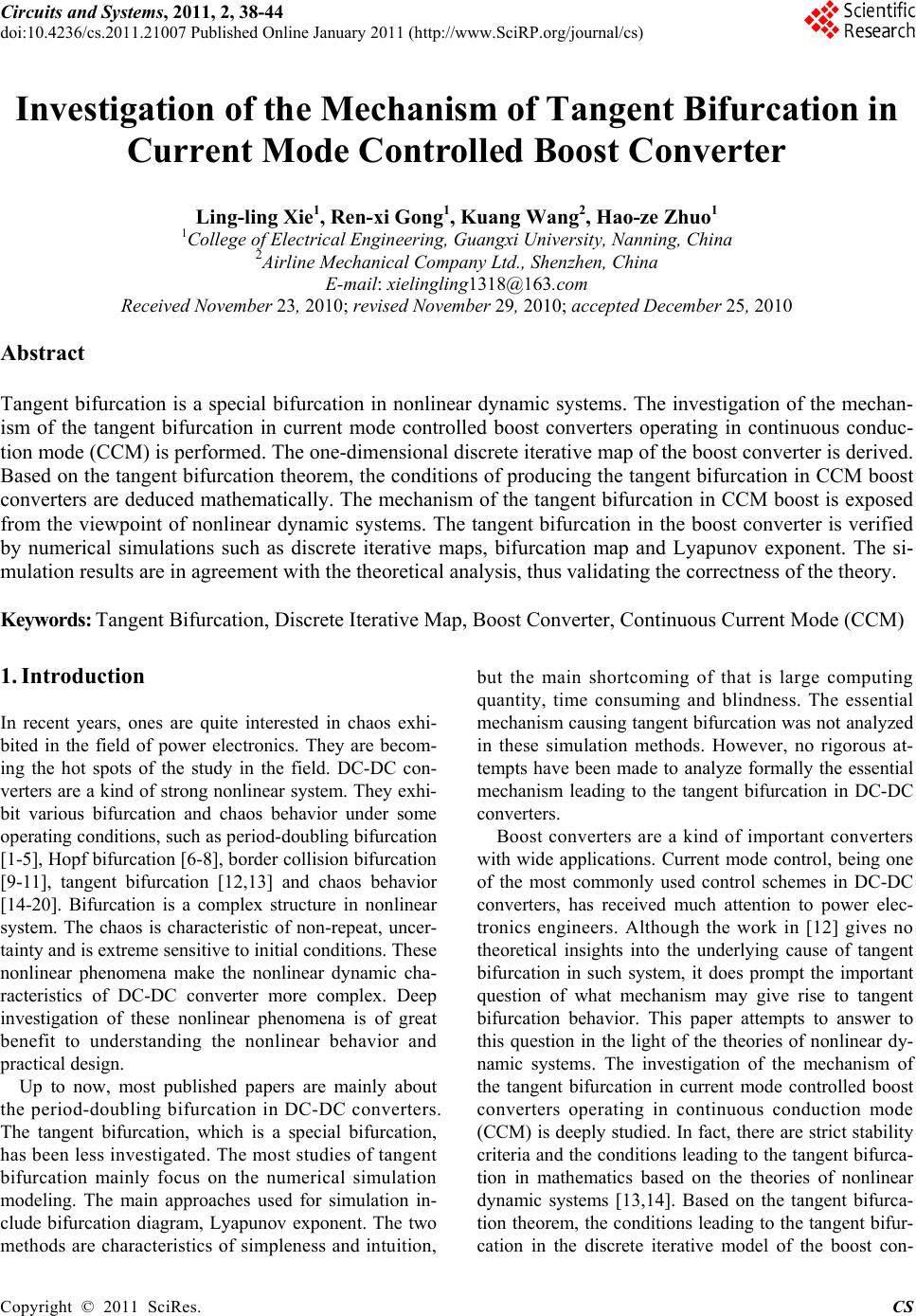 Circuits and Systems, 2011, 2, 38-44 doi:10.4236/cs.2011.21007 Published Online January 2011 (http://www.SciRP.org/journal/cs) Copyright © 2011 SciRes. CS Investigation of the Mechanism of Tangent Bifurcation in Current Mode Controlled Boost Converter Ling-ling Xie1, Ren-xi Gong1, Kuang Wang2, Hao-ze Zhuo1 1College of Electrical Engineering, Guangxi University, Nanning, China 2Airline Mechanical Company Ltd., Shenzhen, China E-mail: xielingling1318@163.com Received November 23, 2010; revised November 29, 2010; accepted December 25, 2010 Abstract Tangent bifurcation is a special bifurcation in nonlinear dynamic systems. The investigation of the mechan- ism of the tangent bifurcation in current mode controlled boost converters operating in continuous conduc- tion mode (CCM) is performed. The one-dimensional discrete iterative map of the boost converter is derived. Based on the tangent bifurcation theorem, the conditions of producing the tangent bifurcation in CCM boost converters are deduced mathematically. The mechanism of the tangent bifurcation in CCM boost is exposed from the viewpoint of nonlinear dynamic systems. The tangent bifurcation in the boost converter is verified by numerical simulations such as discrete iterative maps, bifurcation map and Lyapunov exponent. The si- mulation results are in agreement with the theoretical analysis, thus validating the correctness of the theory. Keywords: Tangent Bifurcation, Discrete Iterative Map, Boost Converter, Continuous Current Mode (CCM) 1. Introduction In recent years, ones are quite interested in chaos exhi- bited in the field of power electronics. They are becom- ing the hot spots of the study in the field. DC-DC con- verters are a kind of strong nonlinear system. They exhi- bit various bifurcation and chaos behavior under some operating conditions, such as period-doubling bifurcation [1-5], Hopf bifurcation [6-8], border collision bifurcation [9-11], tangent bifurcation [12,13] and chaos behavior [14-20]. Bifurcation is a complex structure in nonlinear system. The chaos is characteristic of non-repeat, uncer- tainty and is extreme sensitive to initial conditions. These nonlinear phenomena make the nonlinear dynamic cha- racteristics of DC-DC converter more complex. Deep investigation of these nonlinear phenomena is of great benefit to understanding the nonlinear behavior and practical design. Up to now, most published papers are mainly about the period-doubling bifurcation in DC-DC converters. The tangent bifurcation, which is a special bifurcation, has been less investigated. The most studies of tangent bifurcation mainly focus on the numerical simulation modeling. The main approaches used for simulation in- clude bifurcation diagram, Lyapunov exponent. The two methods are characteristics of simpleness and intuition, but the main shortcoming of that is large computing quantity, time consuming and blindness. The essential mechanism causing tangent bifurcation was not analyzed in these simulation methods. However, no rigorous at- tempts have been made to analyze formally the essential mechanism leading to the tangent bifurcation in DC-DC converters. Boost converters are a kind of important converters with wide applications. Current mode control, being one of the most commonly used control schemes in DC-DC converters, has received much attention to power elec- tronics engineers. Although the work in [12] gives no theoretical insights into the underlying cause of tangent bifurcation in such system, it does prompt the important question of what mechanism may give rise to tangent bifurcation behavior. This paper attempts to answer to this question in the light of the theories of nonlinear dy- namic systems. The investigation of the mechanism of the tangent bifurcation in current mode controlled boost converters operating in continuous conduction mode (CCM) is deeply studied. In fact, there are strict stability criteria and the conditions leading to the tangent bifurca- tion in mathematics based on the theories of nonlinear dynamic systems [13,14]. Based on the tangent bifurca- tion theorem, the conditions leading to the tangent bifur- cation in the discrete iterative model of the boost con- 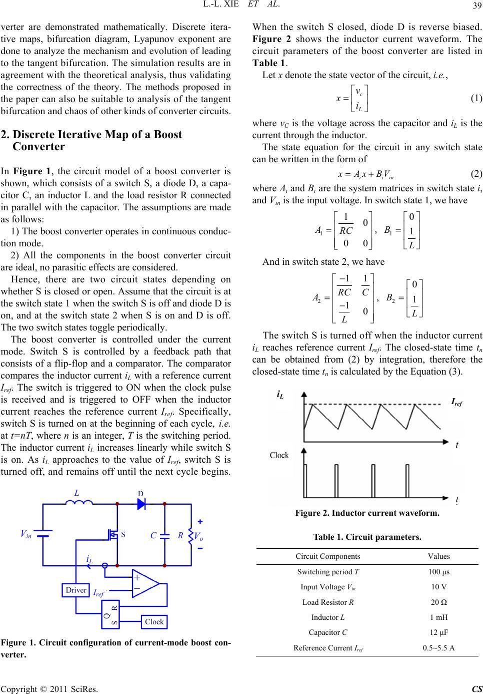 L.-L. XIE ET AL. Copyright © 2011 SciRes. CS 39 verter are demonstrated mathematically. Discrete itera- tive maps, bifurcation diagram, Lyapunov exponent are done to analyze the mechanism and evolution of leading to the tangent bifurcation. The simulation results are in agreement with the theoretical analysis, thus validating the correctness of the theory. The methods proposed in the paper can also be suitable to analysis of the tangent bifurcation and chaos of other kinds of converter circuits. 2. Discrete Iterative Map of a Boost Converter In Figure 1, the circuit model of a boost converter is shown, which consists of a switch S, a diode D, a capa- citor C, an inductor L and the load resistor R connected in parallel with the capacitor. The assumptions are made as follows: 1) The boost converter operates in continuous conduc- tion mode. 2) All the components in the boost converter circuit are ideal, no parasitic effects are considered. Hence, there are two circuit states depending on whether S is closed or open. Assume that the circuit is at the switch state 1 when the switch S is off and diode D is on, and at the switch state 2 when S is on and D is off. The two switch states toggle periodically. The boost converter is controlled under the current mode. Switch S is controlled by a feedback path that consists of a flip-flop and a comparator. The comparator compares the inductor current iL with a reference current Iref. The switch is triggered to ON when the clock pulse is received and is triggered to OFF when the inductor current reaches the reference current Iref. Specifically, switch S is turned on at the beginning of each cycle, i.e. at t=nT, where n is an integer, T is the switching period. The inductor current iL increases linearly while switch S is on. As iL approaches to the value of Iref, switch S is turned off, and remains off until the next cycle begins. Figure 1. Circuit configuration of current-mode boost con- verter. When the switch S closed, diode D is reverse biased. Figure 2 shows the inductor current waveform. The circuit parameters of the boost converter are listed in Table 1. Let x denote the state vector of the circuit, i.e., c L v xi (1) where vC is the voltage across the capacitor and iL is the current through the inductor. The state equation for the circuit in any switch state can be written in the form of . iiin x Ax BV (2) where Ai and Bi are the system matrices in switch state i, and Vin is the input voltage. In switch state 1, we have 1 10 00 ARC , 1 0 1 B L And in switch state 2, we have 2 11 10 RC C A L , 2 0 1 B L The switch S is turned off when the inductor current iL reaches reference current Iref. The closed-state time tn can be obtained from (2) by integration, therefore the closed-state time tn is calculated by the Equation (3). Figure 2. Inductor current waveform. Table 1. Circuit parameter s. Circuit Components Values Switching period T 100 μs Input Voltage Vin 10 V Load Resistor R 20 Ω Inductor L 1 mH Capacitor C 12 μF Reference Current Iref 0.5~5.5 A I re f iL I ref iL t t R C L Vin Vo 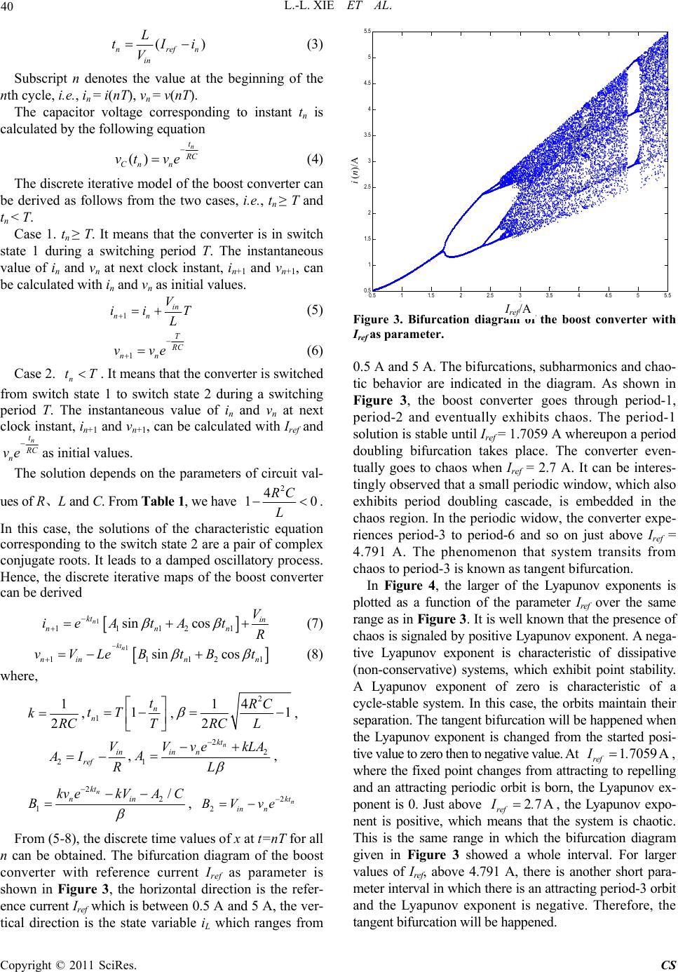 L.-L. XIE ET AL. Copyright © 2011 SciRes. CS 40 () nrefn in L tIi V (3) Subscript n denotes the value at the beginning of the nth cycle, i.e., in = i(nT), vn = v(nT). The capacitor voltage corresponding to instant tn is calculated by the following equation () n t R C Cn n vt ve (4) The discrete iterative model of the boost converter can be derived as follows from the two cases, i.e., tn ≥ T and tn < T. Case 1. tn ≥ T. It means that the converter is in switch state 1 during a switching period T. The instantaneous value of in and vn at next clock instant, in+1 and vn+1, can be calculated with in and vn as initial values. 1 in nn V ii T L (5) 1 T R C nn vve (6) Case 2. n tT. It means that the converter is switched from switch state 1 to switch state 2 during a switching period T. The instantaneous value of in and vn at next clock instant, in+1 and vn+1, can be calculated with Iref and n t R C n ve as initial values. The solution depends on the parameters of circuit val- ues of R、L and C. From Table 1, we have 2 4 10 RC L . In this case, the solutions of the characteristic equation corresponding to the switch state 2 are a pair of complex conjugate roots. It leads to a damped oscillatory process. Hence, the discrete iterative maps of the boost converter can be derived 1 11121 sin cos n kt in nnn V ieAtAt R (7) 1 11121 sin cos ktn ninn n vVLeBtBt (8) where, 1 2 kRC ,11n n t tT T , 2 14 1 2 RC RC L , 2 in ref V AI R , 2 2 1 n kt in n Vve kLA AL , 2 2 1 / n kt nin kv ekVAC B , 2 2 n kt in n BVve From (5-8), the discrete time values of x at t=nT for all n can be obtained. The bifurcation diagram of the boost converter with reference current Iref as parameter is shown in Figure 3, the horizontal direction is the refer- ence current Iref which is between 0.5 A and 5 A, the ver- tical direction is the state variable iL which ranges from 0.5 11.5 22.5 33.5 44.5 55. 5 0.5 1 1.5 2 2.5 3 3.5 4 4.5 5 5.5 Iref/A i(n)/A Figure 3. Bifurcation diagram of the boost converter with Iref as parameter. 0.5 A and 5 A. The bifurcations, subharmonics and chao- tic behavior are indicated in the diagram. As shown in Figure 3, the boost converter goes through period-1, period-2 and eventually exhibits chaos. The period-1 solution is stable until Iref = 1.7059 A whereupon a period doubling bifurcation takes place. The converter even- tually goes to chaos when Iref = 2.7 A. It can be interes- tingly observed that a small periodic window, which also exhibits period doubling cascade, is embedded in the chaos region. In the periodic widow, the converter expe- riences period-3 to period-6 and so on just above Iref = 4.791 A. The phenomenon that system transits from chaos to period-3 is known as tangent bifurcation. In Figure 4, the larger of the Lyapunov exponents is plotted as a function of the parameter Iref over the same range as in Figure 3. It is well known that the presence of chaos is signaled by positive Lyapunov exponent. A nega- tive Lyapunov exponent is characteristic of dissipative (non-conservative) systems, which exhibit point stability. A Lyapunov exponent of zero is characteristic of a cycle-stable system. In this case, the orbits maintain their separation. The tangent bifurcation will be happened when the Lyapunov exponent is changed from the started posi- tive value to zero then to negative value. At 17059 A ref I., where the fixed point changes from attracting to repelling and an attracting periodic orbit is born, the Lyapunov ex- ponent is 0. Just above 27A ref I., the Lyapunov expo- nent is positive, which means that the system is chaotic. This is the same range in which the bifurcation diagram given in Figure 3 showed a whole interval. For larger values of Iref , above 4.791 A, there is another short para- meter interval in which there is an attracting period-3 orbit and the Lyapunov exponent is negative. Therefore, the tangent bifurcation will be happened. i (n)/A I ref/A 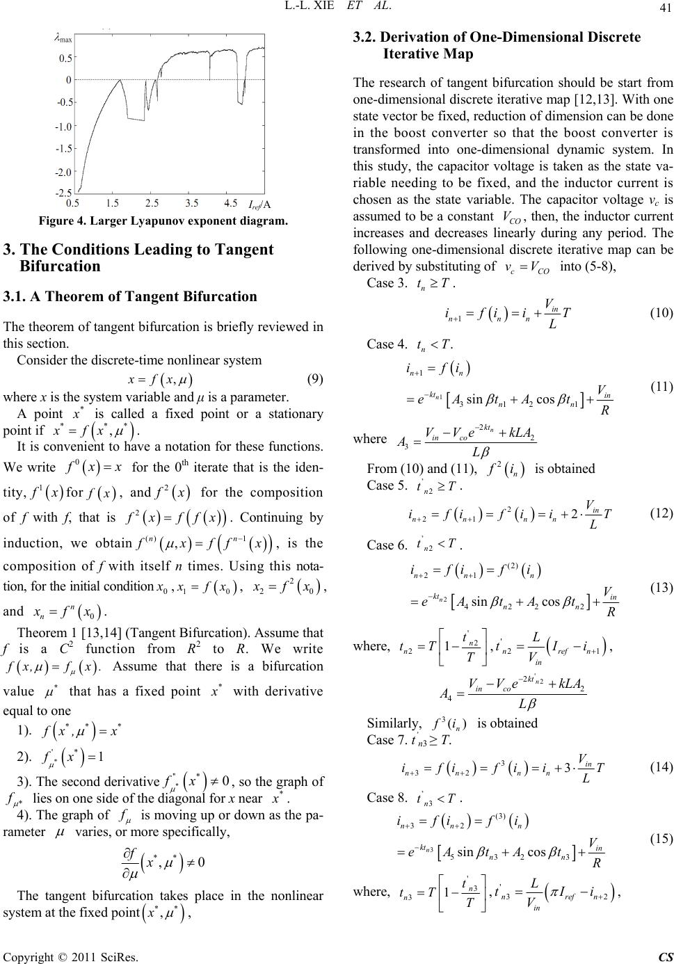 L.-L. XIE ET AL. Copyright © 2011 SciRes. CS 41 Figure 4. Larger Lyapunov exponent diagram. 3. The Conditions Leading to Tangent Bifurcation 3.1. A Theorem of Tangent Bifurcation The theorem of tangent bifurcation is briefly reviewed in this section. Consider the discrete-time nonlinear system ,xfx (9) where x is the system variable and μ is a parameter. A point * x is called a fixed point or a stationary point if *** ,xfx . It is convenient to have a notation for these functions. We write 0 f xx for the 0th iterate that is the iden- tity, 1 f xfor f x, and 2 f x for the composition of f with f, that is 2 f xffx. Continuing by induction, we obtain () 1 , nn f xff x , is the composition of f with itself n times. Using this nota- tion, for the initial condition0 x , 10 x fx, 2 20 x fx, and 0 n n x fx. Theorem 1 [13,14] (Tangent Bifurcation). Assume that f is a C2 function from R2 to R. We write f x,fx . Assume that there is a bifurcation value * that has a fixed point * x with derivative equal to one 1). ** * f x, x 2). * '* 1fx 3). The second derivative * '' *0fx , so the graph of * f lies on one side of the diagonal for x near * x . 4). The graph of f is moving up or down as the pa- rameter varies, or more specifically, ** ,0 fx The tangent bifurcation takes place in the nonlinear system at the fixed point ** ,x , 3.2. Derivation of One-Dimensional Discrete Iterative Map The research of tangent bifurcation should be start from one-dimensional discrete iterative map [12,13]. With one state vector be fixed, reduction of dimension can be done in the boost converter so that the boost converter is transformed into one-dimensional dynamic system. In this study, the capacitor voltage is taken as the state va- riable needing to be fixed, and the inductor current is chosen as the state variable. The capacitor voltage vc is assumed to be a constant CO V, then, the inductor current increases and decreases linearly during any period. The following one-dimensional discrete iterative map can be derived by substituting of cCO vV into (5-8), Case 3. n tT. 1 in nnn V ifiiT L (10) Case 4. . n tT 1 1 312 1 sin cos n nn kt in nn ifi V eAtAt R (11) where 2 2 3 n kt in co VVe kLA AL From (10) and (11), 2 n f i is obtained Case 5. ’ 2n tT. 2 21 2in nn nn V ifi fiiT L (12) Case 6. ’ 2n tT . 2 (2) 21 422 2 sin cos n nn n kt in nn ifi fi V eAtAt R (13) where, ' 2 21n n t tT T , ' 21 nrefn in L tIi V , '2 2 2 4 n kt in co VVe kLA AL Similarly, 3() n f i is obtained Case 7. t’ n3 ≥ T. 3 32 3in nn nn V ifi fiiT L (14) Case 8. ’ 3n tT . 3 (3) 32 532 3 sin cos n nn n kt in nn ifi fi V eAtAt R (15) where, ' 3 31n n t tT T , ' 32 nrefn in L tIi V , I re f /A 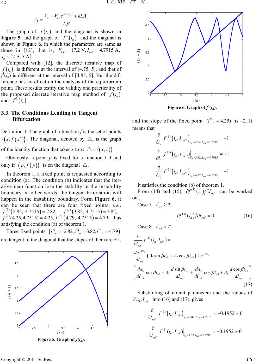 L.-L. XIE ET AL. Copyright © 2011 SciRes. CS 42 '3 2 2 5 n kt in co VVe kLA AL The graph of n f i and the diagonal is shown in Figure 5, and the graph of 3 n f i and the diagonal is shown in Figure 6, in which the parameters are same as those in [12], that is, 17.2 V,4.7915 A, CO ref VI 2 A,5 A n i. Compared with [12], the discrete iterative map of n f i is different at the interval of [4.75, 5], and that of f3(in) is different at the interval of [4.85, 5]. But the dif- ference has no effect on the analysis of the equilibrium point. These results testify the validity and practicality of the proposed discrete iterative map method of n f i and 3 n f i. 3.3. The Conditions Leading to Tangent Bifurcation Definition 1. The graph of a function f is the set of points , x fx . The diagonal, denoted by △, is the graph of the identity function that takes x to x: △ , x x Obviously, a point p is fixed for a function f if and only if , p fp is on the diagonal △. In theorem 1, a fixed point is requested according to condition (a). The condition (b) indicates that the iter- ative map function lose the stability in the instability boundary, in other words, the tangent bifurcation will happen in the instability boundary. Form Figure 6, it can be seen that there are four fixed points, i.e., 3(3) 2.82, 4.75152.82,3.82, 4.75153.82,ff 3(3) (4.25,4.7515)4.25,4.79, 4.75154.79ff , thus satisfying the condition (a) of theorem 1. Three fixed points *1*2 *4 2.82, 3.82,4.79 nnn iii are tangent to the diagonal that the slopes of them are +1, 22.5 33.5 44.5 5 2 2. 5 3 3. 5 4 4. 5 5 in i(n+1) Figure 5. Graph of f(in). 22.5 33.5 44.5 5 2 2.5 3 3.5 4 4.5 5 in i(n+3) Figure 6. Graph of f3(in). and the slope of the fixed point *3 (4.25) n i is –2. It means that (3) 2.82, 4.7915 ,, 1 nref nref iI n fiI i (3) 3.82, 4.7915 ,, 1 nref nref iI n fiI i (3) 4.79, 4.7915 ,, 1 nref nref iI n fiI i It satisfies the condition (b) of theorem 1. From (14) and (15), (3) nref f iI can be worked out, Case 7. ’ 3. n tT (3) 0 nref fi I (16) Case 8. ’ 3n tT . 3 3 (3) 532 3 53 3 2 35 32 , sin cos sin cos sin cos nref ref ktn ktn nn ref nn nn refref refref fiI i de AtAte dI dAd tdt dA tA tA dIdI dIdI (17) Substituting of circuit parameters and the values of CO ref V,I into (16) and (17), gives (3) 2.82, 4.7915 ,0.1952 0 nref nref iI ref fiI I (3) 3.82, 4.7915 ( ,)0.19520 nref nref iI ref fiI I i (n) i (n + 1) i (n) i (n + 3) 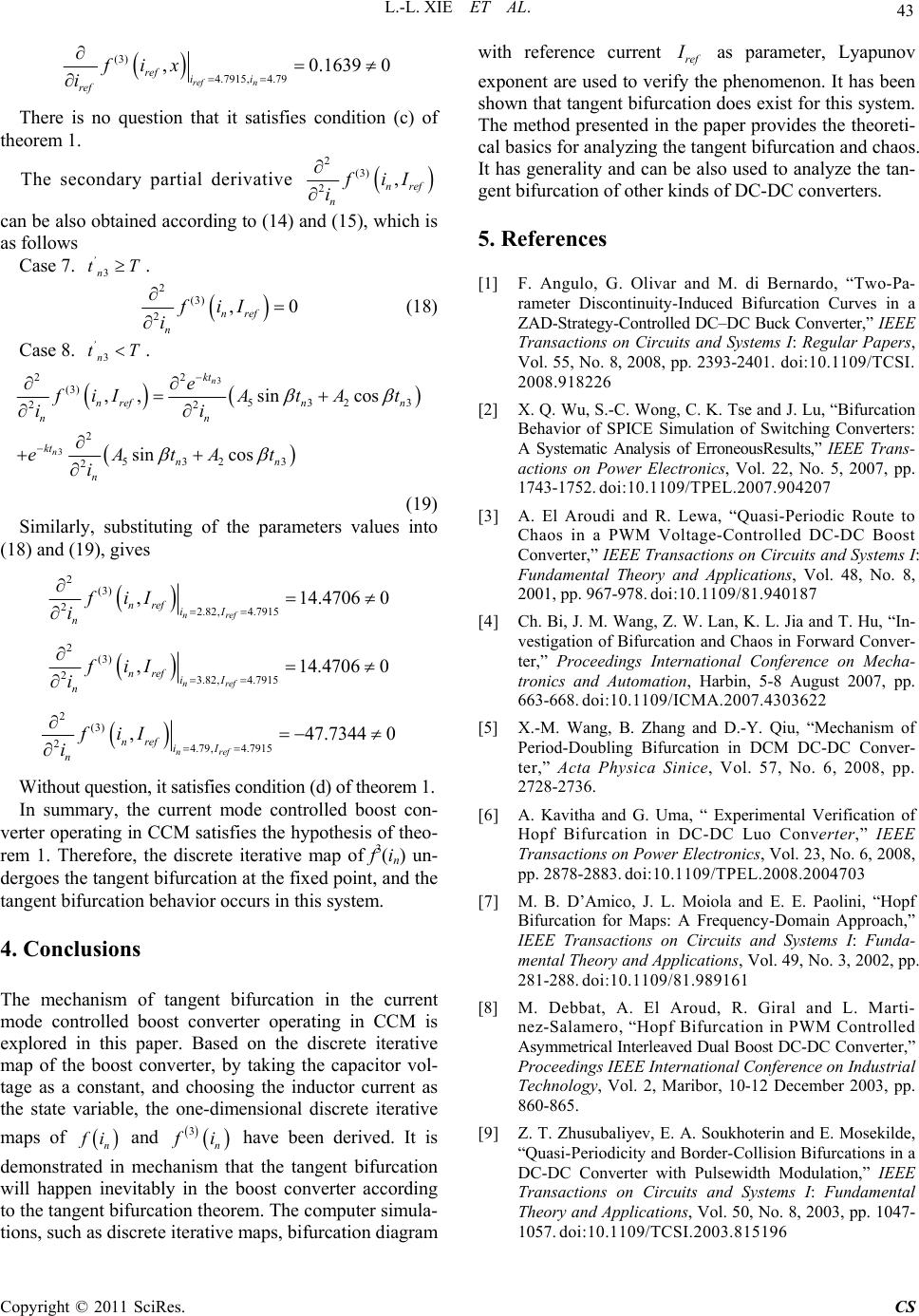 L.-L. XIE ET AL. Copyright © 2011 SciRes. CS 43 (3) 4.7915, 4.79 ,0.16390 ref n ref ii ref fix i There is no question that it satisfies condition (c) of theorem 1. The secondary partial derivative 2 (3) 2, nref n f iI i can be also obtained according to (14) and (15), which is as follows Case 7. 3 ’ n tT. 2 (3) 2,0 nref n fiI i (18) Case 8. 3 ’ n tT. 3 3 22 (3) 5323 22 2 532 3 2 ,,sin cos sin cos n n kt nrefn n nn kt nn n e f iIAt At ii eAtAt i (19) Similarly, substituting of the parameters values into (18) and (19), gives 2 (3) 22.82, 4.7915 ,14.4706 0 nref nref iI n fiI i 2 (3) 23.82, 4.7915 ,14.4706 0 nref nref iI n fiI i 2 (3) 24.79, 4.7915 ,47.7344 0 nref nref iI n fiI i Without question, it satisfies condition (d) of theorem 1. In summary, the current mode controlled boost con- verter operating in CCM satisfies the hypothesis of theo- rem 1. Therefore, the discrete iterative map of f3(in) un- dergoes the tangent bifurcation at the fixed point, and the tangent bifurcation behavior occurs in this system. 4. Conclusions The mechanism of tangent bifurcation in the current mode controlled boost converter operating in CCM is explored in this paper. Based on the discrete iterative map of the boost converter, by taking the capacitor vol- tage as a constant, and choosing the inductor current as the state variable, the one-dimensional discrete iterative maps of n f i and 3 n f i have been derived. It is demonstrated in mechanism that the tangent bifurcation will happen inevitably in the boost converter according to the tangent bifurcation theorem. The computer simula- tions, such as discrete iterative maps, bifurcation diagram with reference current ref I as parameter, Lyapunov exponent are used to verify the phenomenon. It has been shown that tangent bifurcation does exist for this system. The method presented in the paper provides the theoreti- cal basics for analyzing the tangent bifurcation and chaos. It has generality and can be also used to analyze the tan- gent bifurcation of other kinds of DC-DC converters. 5. References [1] F. Angulo, G. Olivar and M. di Bernardo, “Two-Pa- rameter Discontinuity-Induced Bifurcation Curves in a ZAD-Strategy-Controlled DC–DC Buck Converter,” IEEE Transactions on Circuits and Systems I: Regular Papers, Vol. 55, No. 8, 2008, pp. 2393-2401. doi:10.1109/TCSI. 2008.918226 [2] X. Q. Wu, S.-C. Wong, C. K. Tse and J. Lu, “Bifurcation Behavior of SPICE Simulation of Switching Converters: A Systematic Analysis of ErroneousResults,” IEEE Trans- actions on Power Electronics, Vol. 22, No. 5, 2007, pp. 1743-1752. doi:10.1109/TPEL.2007.904207 [3] A. El Aroudi and R. Lewa, “Quasi-Periodic Route to Chaos in a PWM Voltage-Controlled DC-DC Boost Converter,” IEEE Transactions on Circuits and Systems I: Fundamental Theory and Applications, Vol. 48, No. 8, 2001, pp. 967-978. doi:10.1109/81.940187 [4] Ch. Bi, J. M. Wang, Z. W. Lan, K. L. Jia and T. Hu, “In- vestigation of Bifurcation and Chaos in Forward Conver- ter,” Proceedings International Conference on Mecha- tronics and Automation, Harbin, 5-8 August 2007, pp. 663-668. doi:10.1109/ICMA.2007.4303622 [5] X.-M. Wang, B. Zhang and D.-Y. Qiu, “Mechanism of Period-Doubling Bifurcation in DCM DC-DC Conver- ter,” Acta Physica Sinice, Vol. 57, No. 6, 2008, pp. 2728-2736. [6] A. Kavitha and G. Uma, “ Experimental Verification of Hopf Bifurcation in DC-DC Luo Converter,” IEEE Transactions on Power Electronics, Vol. 23, No. 6, 2008, pp. 2878-2883. doi:10.1109/TPEL.2008.2004703 [7] M. B. D’Amico, J. L. Moiola and E. E. Paolini, “Hopf Bifurcation for Maps: A Frequency-Domain Approach,” IEEE Transactions on Circuits and Systems I: Funda- mental Theory and Applications, Vol. 49, No. 3, 2002, pp. 281-288. doi:10.1109/81.989161 [8] M. Debbat, A. El Aroud, R. Giral and L. Marti- nez-Salamero, “Hopf Bifurcation in PWM Controlled Asymmetrical Interleaved Dual Boost DC-DC Converter,” Proceedings IEEE International Conference on Industrial Technology, Vol. 2, Maribor, 10-12 December 2003, pp. 860-865. [9] Z. T. Zhusubaliyev, E. A. Soukhoterin and E. Mosekilde, “Quasi-Periodicity and Border-Collision Bifurcations in a DC-DC Converter with Pulsewidth Modulation,” IEEE Transactions on Circuits and Systems I: Fundamental Theory and Applications, Vol. 50, No. 8, 2003, pp. 1047- 1057. doi:10.1109/TCSI.2003.815196  L.-L. XIE ET AL. Copyright © 2011 SciRes. CS 44 [10] M. Yue, C. K. Tse, T. Kousaka and H. Kawakami, “Connecting Border Collision with Saddle-Node in Switched Dynamical Systems,” IEEE Transactions on Circuits and Systems II: Express Briefs, Vol. 52, No. 9, 2005, pp. 581-585. doi:10.1109/TCSII.2005.850488 [11] H. Khammari and M. Benrejeb, “Tangent Bifurcation in Doubling Period Process of a Resonant Circuit’s Res- ponses,” Proceedings IEEE International Conference on Industrial Technology, Vol. 3, Hammamet, 8-10 Decem- ber 2004, pp. 1281-1286. [12] Y. F. Zhou and J. N. Chen, “Tangent Bifurcation and Intermittent Chaos in Current-Mode Controlled Boost Converter,” Proceedings of the Chinese Society for Elec- trical Engineering, Vol.25, No.1, 2005, pp. 23-26. [13] B. L. Hao, “Starting with Parabolas, an Introduction to Chaotic Dynamics,” Shanghai Scientific and Technolo- gical Education Publishing House, Shanghai, 1993. [14] R. C. Robinson, “An Introduction to Dynamical Systems: Continuous and Discrete,” Pearson Prentice Hall, New Jersey, 2004. [15] C. K. Tse, “Flip Bifimcation and Chaos in the Three- State Boost Switching Regulars,” IEEE Transactions on Circuits Systems I: Fundamental Theory and Applications, Vol. 41, No. 1, 1994, pp. 16-23. doi:10.1109/81.260215 [16] C. K. Tse and M. di Bernardo, “Complex Behavior in Switching Power Converters,” Proceedings of the IEEE, Vol. 90, No. 5, 2002, pp. 768-781. doi:10.1109/JPROC. 2002.1015006 [17] B. Basak and S. Parui, “Exploration of Bifurcation and Chaos in Buck Converter Supplied from a Rectifier,” IEEE Transactions on Power Electronics, Vol. 25, No. 6, 2010, pp. 1556-1564. doi:10.1109/TPEL.2009.2035500 [18] F.-H. Hsieh, K.-M. Lin and J.-H. Su, “Chaos Phenome- non in UC3842 Current-Programmed Flyback Conver- ters,” Proceedings IEEE Conference on Industrial Elec- tronics and Applications, Xi’an, 25-27 May 2009, pp. 166-171. [19] J. H. Chen, K. T. Chau and C. C. Chan, “Analysis of Chaos in Current-Mode-Controlled DC Drive Systems,” IEEE Transactions on Industrial Electronics, Vol. 47, No. 1, 2000, pp. 67-76. doi:10.1109/41.824127 [20] K. W. E. Cheng, M. J. Liu and Y. L. Ho, “Experimental Confirmation of Frequency Correlation for Bifurcation in Current-Mode Controlled Buck-Boost Converters,” IEEE Power Electronics Letters, Vol. 1, No. 4, 2003, pp. 101-103. doi:10.1109/LPEL.2004.825548 |