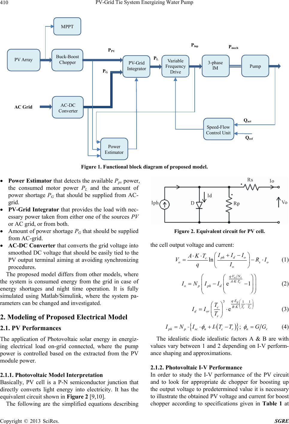
PV-Grid Tie System Energizing Water Pump
Copyright © 2013 SciRes. SGRE
418
Amsterdam, 1986.
[8] E. V. Meidanis, G. A. Vokas and J. K. Kaldellis, “Theo-
retical Simulation and Experimental Analysis of a PV-
Based Water Pumping System,” Lab of Soft Energy Ap-
plications & Environmental Protection, TEI of Piraeus.
powerelectronics.teipir.gr/Papers/MEDPOWER08_170.pdf
[9] J. Appelbaum and J. Bany, “Performance Analysis of DC
Motor Photovoltaic Converter System,” Solar Energy,
Vol. 22, No. 5, 1979, pp. 439-445.
doi:10.1016/0038-092X(79)90173-7
[10] M. Abu-Aligh, “Design of Photovoltaic Water Pumping
System and Compare It with Diesel Powered Pump,”
JJMIE, Vol. 5, No. 3, 2011, pp. 273-280.
[11] The Mathworks, Inc., “Matlab and Simulink,” Version
R2010a. http://www.mathworks.com
[12] S. B. Kjaer, J. K. Pedersen and F. Blaabjerg, “A Review
of Single-Phase Grid-Connected Inverters for Photovol-
taic Modules,” IEEE Transactions on Industry Applica-
tions, Vol. 41, No. 5, 2005, pp. 1292-1306.
doi:10.1109/TIA.2005.853371
[13] S. J. Chapman, “Electric Machinery Fundamentals,” Mc-
Graw-Hill, New York, 2003.
[14] G. McPherson and R. D. Laramore, “An Introduction to
Electric Machines and Transformers,” Wiley, New York,
1990.
[15] A. K. Daud and M. M. Marwan, “Solar Powered Induc-
tion-Motor Water Pump Operating on a Desert Well,
Simulation & Field Tests,” Renewable Energy Journal,
Vol. 30, No. 5, 2005, pp. 701-714.
doi:10.1016/j.renene.2004.02.016
[16] M. Benghanem and A. H. Arab, “Photovoltaic Water
Pumping Systems for Algeria,” Desalination, Vol. 209,
No. 1-3, 2007, pp. 50-57.
[17] S. Khader and A. K. Daud, “Photovoltaic-Grid Integrated
System,” 2012 First International Conference on Renew-
able Energies and Vehicular Technology, Hammamet,
26-28 March 2012, pp. 60-65.
doi:10.1109/REVET.2012.6195249
Nomenclature
A,B diode idealistic factors
Eg band gap energy of the semiconductor
fn rated supply voltage frequency
g gravity acceleration (9.8 m/s2)
G solar irradiation
Gr reference solar irradiation
h reservoir elevation (m)
H total head (m)
HA total installation head (m)
HS static head (m)
HL network hydraulic losses (m)
water density (1000 kg/m3)
ηp pump efficiency (%)
Id diode saturation current
IMPP PV module current at maximum power
Io cell current
Iph cell photo current
Ipv Photovoltaic current
Isc short circuit current
Ior,It constants given at standard conditions
IL1 motor line current
K Boltzman constant
n rotor speed in rpm
ns motor synchronous speed in rpm
Np number of parallel connected cells
Npm number of parallel connected PV modules
Ns number of series connected cells
Nsm number of series connected PV modules
p number of motor poles
PG grid power
Pconst constant losses power
PL load consumed power
Pem electromagnetic power
Pmech net mechanical power
RLoad load resistance
Rp PV intersinc shunt resistance
Rs PV intersinc series resistance
R1 stator resistance of induction motor
R’2 rotor resistance motor referred to stator
R’th Thevinen resistance referred to stator
Rinp total input stator resistance
Q electric charge (Coulomb)
Q water flow-rate (m3/hr)
Ppv Photovoltaic generated power
PV Photovoltaic
Pinp motor input power
Tc cell temperature in Kelvin
Tem electromagnetic torque (N·m)
Tm motor net mechanical torque (Nm)
Tr reference temperature in Kelvin
VFD Variable Frequency Drive
VMPP PV module voltage at maximum power
VO cell output voltage
VOC PV module open circuit voltage
Vph terminal phase voltage
Vpv array photovoltaic voltage
Vth Thevinen voltage
Xm magnetic reactance
X1 stator reactance of induction mptor
X’2 rotor reactance of induction motor referred to stator
X’th Thevinen reactance referred to stator
Xinp total input stator reactance
Zth Thevinen impedance
Zinp total input stator impedance
n normalized insulation
motor phase shift angle
rotor speed in rad/s
friction coefficient