Energy and Power Engineering, 2013, 5, 52-56
doi:10.4236/epe.2013.53B011 Published Online May 2013 (http://www.scirp.org/journal/epe)
Reliability Improvement Strategies for HVDC
Transmission System
Yidong Hong, Tao Yu
Institute of Power, South China University of Technology, Guangzhou, China
Email: hongyidong1989@126.com
Received 2013
ABSTRACT
This paper analyses reliability data of HVDC systems of Southern China Power Grid. The weak links of HVDC sys-
tems’ operational reliability are DC control and protection, valve hall and v alve cooling system and transmission lines.
Some improvement measures and HVDC system reliability technology are proposed in this paper.
Keywords: HVDC; Transmission; Operation; Reliability
1. Introduction
HVDC Transmission has obvious advantages in the re-
spect of long distance transmission on a large scale and
interconnection of power systems. It's significant for
west-east power transmission and national interconnec-
tion of power systems in China. The reliability in HVDC
systems indicates the amount of power transmitted in
specified time, conditions and environment. [1] Data
shows that the availability rate of operating HVDC sys-
tems is over 90 percent. It has been proposed in Inter-
Mountain HVDC system that reliability level of bipolar
HVDC should be higher than double-circuit AC lines.
More requirements are raised for the reliab ility of HVDC
systems with the technology of HVDC developing and
more real projects go into oper ation. The improv ement of
reliability would bring great benefits to the safe, reliable
and economic operation of the systems. Thus, reinforcing
the work of analysis about reliability indices and man-
agement of reliability is good for searching the weak
links and influencing factors of reliability scientifically.
Taking measures to improve HVDC systems reliability
can guarantee the secure and available operation of HVDC
systems.
2. Analysis of Reliability Indices of HVDC
Systems
Statistics of HVDC transmission systems include con-
verter transformers, converter valves, AC filters, capaci-
tor, and DC filers, smoothing reactor, transmission lines
and control protection devices. While failure types in
HVDC systems are various and complex, they can be
classified into six types: AC and its device, Converter
Valve, DC control and protection, primary equipments,
transmission lines and others. [2-3]
Failures in HVDC systems have a great influence on
operating reliability so that reliability indices are influ-
enced directly or indirectly. Through statistics and analy-
sis of reliability indices of Tianguang, Gaozhao, Xingan
and Chusui HVDC systems during 2005 to 2011, it's ob-
vious that DC block have a great impact on safe and re-
liable operation of HVDC systems. So the reasons that
may cause DC blocks are analyzed and classified spe-
cifically.
It's shown in the statistics and classification of causes
of DC blocks that monopole block and bipolar blocks are
both mainly caused by failures in primary equipments,
control and protection system, valve hall and valve cool-
ing system, transmission lines and AC protection. Ac-
cording to statistics, there are 110 DC blocks during
2005 to 2011 in these four HVDC systems. The causes
leading to DC blocks are 6 times of primary equipments,
48 times of DC control and protection, 18 times of valve
cooling systems,37 times of transmission lines and 1 time
of AC protection. They account for 5.45 percent, 43.64
percent, 16.36 percent, 33.64 percent, and 0.91 percent
separately as is shown in Figure 1.
From Table 1 and Figure 1, it's shown that measures
should be taken to improve operating reliability of
HVDC system. According to the distribu tion of causes of
DC blocks in daily operation, this paper focuses on DC
control protection and valve hall and valve cooling sys-
tem to improve operation reliability o f HVDC systems.
Copyright © 2013 SciRes. EPE
Y. D. HONG, T. YU 53
Table 1. Statistics and Classification of Causes of HVDC Systems’ Blocks.
HVDC System Block Reasons 20052006200720082009 2010 2011Sum
Monopole BlockTimes 5 7 10 5 1 3 2 33
Bipolar BlockTimes 1 1 3 0 0 0 0 5
Primary Equipment 1 0 0 0 0 0 0 1
Control and Protection E q ui pment 1 1 10 4 1 1 1 19
Valve Hall and its Cooling System 1 4 0 1 0 0 1 7
Transmission Lines 3 2 3 0 0 2 0 10
Tianguang HVDC System
AC Protection 0 1 0 0 0 0 0 1
Monopole BlockTimes 6 8 5 7 5 3 4 38
Bipolar BlockTimes 0 1 1 0 0 0 0 2
Primary Equipment 0 1 1 0 0 1 0 3
Control and Protection E q ui pment 2 6 2 2 2 0 2 16
Valve Hall and its Cooling System 3 1 0 1 1 0 1 7
Transmission Lines 1 1 3 4 2 2 1 14
Gaozhao HVDC System
AC Protection 0 0 0 0 0 0 0 0
Monopole BlockTimes --- --- --- 8 5 6 1 20
Bipolar BlockTimes --- --- --- 4 0 0 0 4
Primary Equipment --- --- --- 1 0 1 0 2
Control and Protection Equipment --- --- --- 4 4 2 2 12
Valve Hall and its Cooling System --- --- --- 1 0 1 1 3
Transmission Lines --- --- --- 6 1 2 1 10
Xingan HVDC System
AC Protection --- --- --- 0 0 0 0 0
Monopole BlockTimes --- --- --- --- --- 2 3 5
Bipolar BlockTimes --- --- --- --- --- 0 0 0
Primary Equipment --- --- --- --- --- 0 0 0
Control and Protection Equipment --- --- --- --- --- 1 0 1
Valve Hall and its Cooling System --- --- --- --- --- 0 1 1
Transmission Lines --- --- --- --- --- 1 2 3
Chusui HVDC system
AC Protection --- --- --- --- --- 0 0 0
Figure 1. Number of Causes of DC Blocks in HVDC Systems.
3. Reliability Strategies of DC control and
Protection
3.1. High Resistance Fault Detection Using
Broadband Fault Signal in HVDC
Transmission Lines
The acts of rejection of transmission line primary protec-
tion and fault location device caused by failure of high
resistence happen occasionally. For example, a high re-
sistance grounded failure happened in pole two in Gaoz-
hao HVDC systems in July 8th, 2004, which led to the
block of pole two. Another high resistence grounded
failure happened in pole two in Tianguang HVDC sys-
tem in May 15th, 2005.The fault location device didn't
act in both two failures. [4,5]
Copyright © 2013 SciRes. EPE
Y. D. HONG, T. YU
54
When high resistence fault happens in transmission
lines, the reason why protection and location devices act
insensitively or even reject action is that the signature
information reflecting high resistence grounded fault is
not obvious. Sampling frequency in existing transmission
lines protection device is not more than 10 kHz, which is
0 to 5 kHz in fact. And it's difficult to extract transient
signature information because only simple signal proc-
essing algorithms like differential and integral are used.
On the other hand, in order to guarantee enough high
resolution of ranging, the sampling frequency in existing
travelling wave location dev ice is more than 1 MHz. But
travelling wave location device limits the bandwidth of
analog input signal to eliminate the disturbance of high
frequency. The passband of analog filter circuit is 5 to
100 kHz. So it's difficult for the existing transmission
lines protection device and travelling wave location de-
vice to effectively detect high resistence fault. [6-8]
To solve the problem of high resistence fault detection,
the most effective way is to extract the subtle transient
feature information. HVDC transmission lines high re-
sistence fault detection uses broadband fault information
which is 0 to 500 kHz and requires that the sampling
frequency of the device should be high enough and a
fault transient feature extraction algorithm should be
constructed. [9]On account of the problem of rejection of
transmission lines protection and travelling location de-
vice when high resistence fault happens, some solutions
are proposed as follow.
1) For a certain resolution of location device, the
broader the frequency band is, the less the location result
is affected by tansition resistence. When location device
resolution and frequency band is rather high, the impact
of transiton resistence on ranging result is eliminated
basically, which effectively solve the problem of big error
in location under the condition of high resistence fault.
2) Based on the broadband and high resolution, it can
be known that wave velo city is only related to fault posi-
tion. According to different fault positions, adopting dif-
ferent wave velocity which corresponds to different fre-
quency component to calculate distance is an effective
way to solve the problem of impact of fault position on
wave velocity.
3) According to different features of maximum of noisy
singal and fault wave singular point under the wavelet
transform, the accurate detection of fault wave head can
be realized. According to different resolution and different
features of fault waveform, singular point can be calcu-
lated accurately by corresponding methods.
4) The broadband fault information and DC travelling
wave location based on wave velo city optimization algo-
rithm can be applicated into monopole single end, mono-
pole double end, bipolar single end and bipolar double
end fault location. It can improve the location accurance's
adaptability for different fault distance and robustness of
transient resistence.
3.2. High Voltage Direct Current Filter Modeling
and Fault Simulation Based on
PSCAD-EMTDC
Since Gaozhao and Xingan HVDC system went into op-
eration, there were problems that DC filter quited opera-
tion or even caused system block.The DC filter protection
of Anshun converter station has acted 10 times since 2004,
where capacitor C1 unbalance protection acted 8 times.
A model of DC filter is constructed by electric mag-
netic simulation program PACAD-EMTDC. It could be
used to detect fault, simulate faults in DC filter and ana-
lyze fault features. The model construction is showed as
Figrure 2.
Figure 2. Construction of HVDC DC Filter Mode based on PSCAD-EMTDC.
Copyright © 2013 SciRes. EPE
Y. D. HONG, T. YU 55
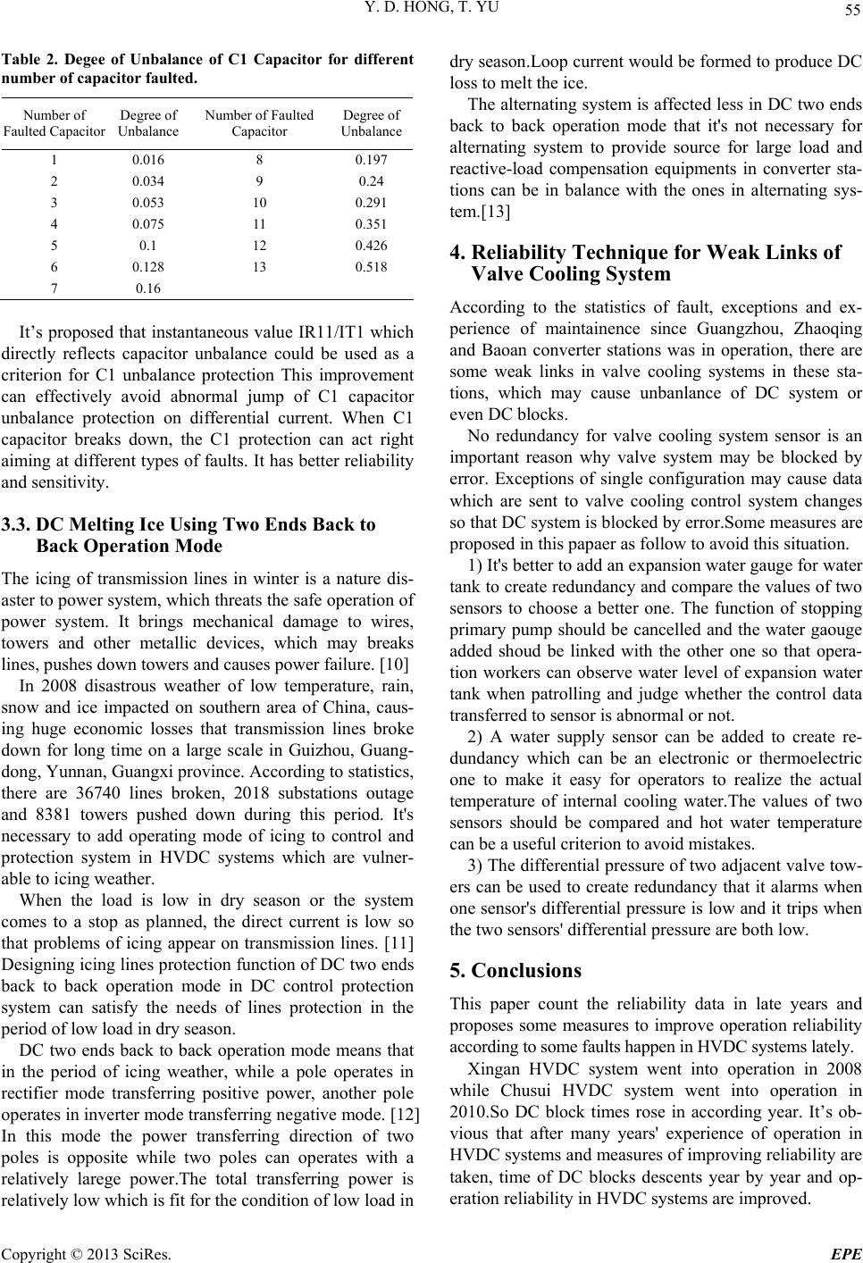
Table 2. Degee of Unbalance of C1 Capacitor for different
number of capacitor faulted.
Number of
Faulted Capacitor Degree of
Unbalance Number of Faulted
Capacitor Degree of
Unbalance
1 0.016 8 0.197
2 0.034 9 0.24
3 0.053 10 0.291
4 0.075 11 0.351
5 0.1 12 0.426
6 0.128 13 0.518
7 0.16
It’s proposed that instantaneous value IR11/IT1 which
directly reflects capacitor unbalance could be used as a
criterion for C1 unbalance protection This improvement
can effectively avoid abnormal jump of C1 capacitor
unbalance protection on differential current. When C1
capacitor breaks down, the C1 protection can act right
aiming at different types of faults. It has better reliability
and sensitivity.
3.3. DC Melting Ice Using Two Ends Back to
Back Operation Mode
The icing of transmission lines in winter is a nature dis-
aster to power system, which threats the safe operation of
power system. It brings mechanical damage to wires,
towers and other metallic devices, which may breaks
lines, pushes down towers and causes power failure. [10]
In 2008 disastrous weather of low temperature, rain,
snow and ice impacted on southern area of China, caus-
ing huge economic losses that transmission lines broke
down for long time on a large scale in Guizhou, Guang-
dong, Yunnan, Guangxi province. According to statistics,
there are 36740 lines broken, 2018 substations outage
and 8381 towers pushed down during this period. It's
necessary to add operating mode of icing to control and
protection system in HVDC systems which are vulner-
able to icing weather.
When the load is low in dry season or the system
comes to a stop as planned, the direct current is low so
that problems of icing appear on transmission lines. [11]
Designing icing lines protection function of DC two ends
back to back operation mode in DC control protection
system can satisfy the needs of lines protection in the
period of low load in dry season.
DC two ends back to back operation mode means that
in the period of icing weather, while a pole operates in
rectifier mode transferring positive power, another pole
operates in inverter mode transferring negative mode. [12]
In this mode the power transferring direction of two
poles is opposite while two poles can operates with a
relatively larege power.The total transferring power is
relatively low which is fit for the conditio n of low lo ad in
dry season.Loop cu rrent would be formed to produce DC
loss to melt the ice.
The alternating system is affected less in DC two ends
back to back operation mode that it's not necessary for
alternating system to provide source for large load and
reactive-load compensation equipments in converter sta-
tions can be in balance with the ones in alternating sys-
tem.[13]
4. Reliability Technique for Weak Links of
Valve Cooling System
According to the statistics of fault, exceptions and ex-
perience of maintainence since Guangzhou, Zhaoqing
and Baoan converter stations was in operation, there are
some weak links in valve cooling systems in these sta-
tions, which may cause unbanlance of DC system or
even DC blocks.
No redundancy for valve cooling system sensor is an
important reason why valve system may be blocked by
error. Exceptions of single configuration may cause data
which are sent to valve cooling control system changes
so that DC system is blocked by error.Some measures are
proposed in this papaer as follow to avoid this situation.
1) It's better to add an expansion water gauge for water
tank to create redundancy and compare the values of two
sensors to choose a better one. The function of stopping
primary pump should be cancelled and the water gaouge
added shoud be linked with the other one so that opera-
tion workers can observe water level of expansion water
tank when patrolling and judge whether the control data
transferred to sensor is abnormal or not.
2) A water supply sensor can be added to create re-
dundancy which can be an electronic or thermoelectric
one to make it easy for operators to realize the actual
temperature of internal cooling water.The values of two
sensors should be compared and hot water temperature
can be a useful criterion to avoid mistakes.
3) The differential pressure of two adjacent valve tow-
ers can be used to create redundancy that it alarms when
one sensor's differential pressure is low and it trips when
the two sensors' differential pressure are both low.
5. Conclusions
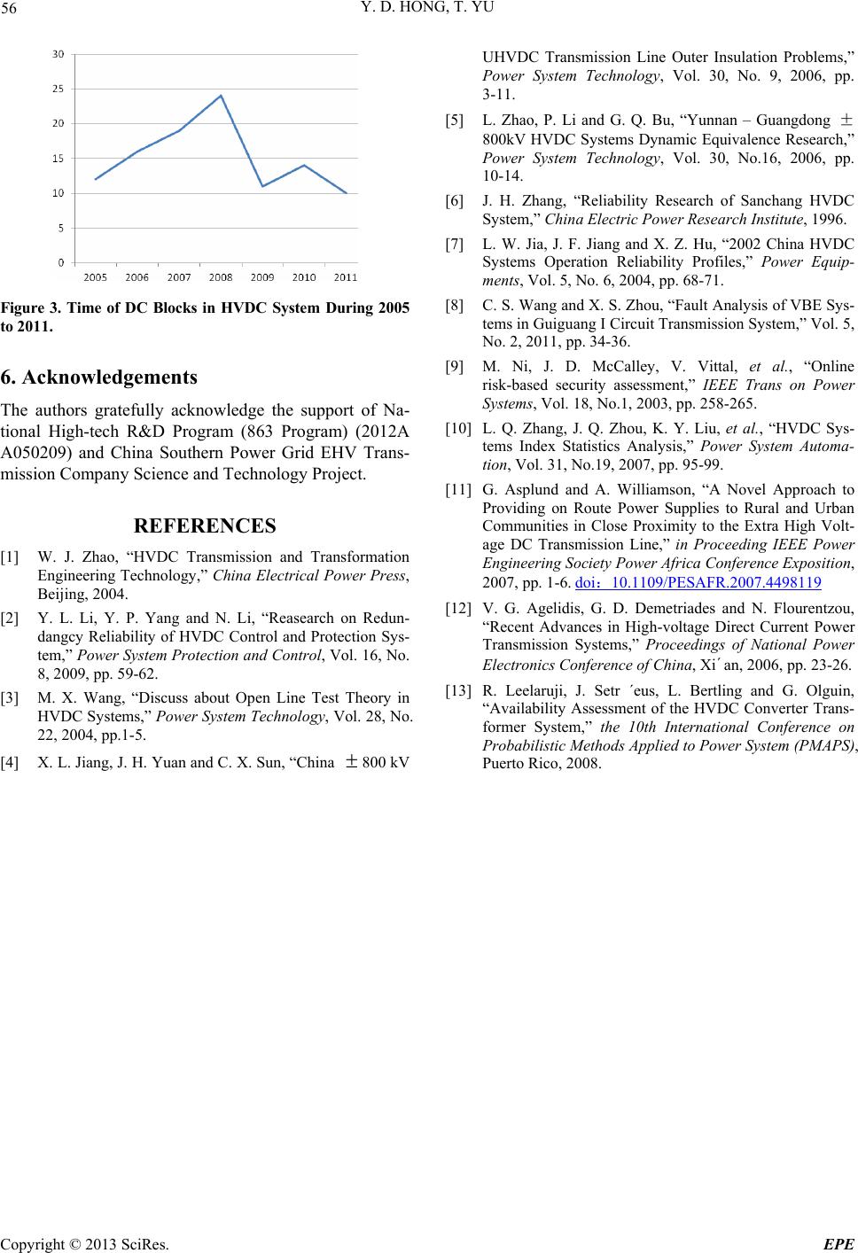
This paper count the reliability data in late years and
proposes some measures to improve operation reliability
according to some faults happen in HVDC systems lately.
Xingan HVDC system went into operation in 2008
while Chusui HVDC system went into operation in
2010.So DC block times rose in according year. It’s ob-
vious that after many years' experience of operation in
HVDC systems and measures of improving reliability are
taken, time of DC blocks descents year by year and op-
eration reliability in HVDC systems are improved.
Copyright © 2013 SciRes. EPE
Y. D. HONG, T. YU
56
Figure 3. Time of DC Blocks in HVDC System During 2005
to 2011.
6. Acknowledgements
The authors gratefully acknowledge the support of Na-
tional High-tech R&D Program (863 Program) (2012A
A050209) and China Southern Power Grid EHV Trans-
mission Company Science and Technology Project.
REFERENCES
[1] W. J. Zhao, “HVDC Transmission and Transformation
Engineering Technology,” China Electrical Power Press,
Beijing, 2004.
[2] Y. L. Li, Y. P. Yang and N. Li, “Reasearch on Redun-
dangcy Reliability of HVDC Control and Protection Sys-
tem,” Power System Protection and Control, Vol. 16, No.
8, 2009, pp. 59-62.
[3] M. X. Wang, “Discuss about Open Line Test Theory in
HVDC Systems,” Power System Technology, Vol. 28, No.
22, 2004, pp.1-5.
[4] X. L. Jiang, J. H. Yuan and C. X. Sun, “China
800 kV
UHVDC Transmission Line Outer Insulation Problems,”
Power System Technology, Vol. 30, No. 9, 2006, pp.
3-11.
[5] L. Zhao, P. Li and G. Q. Bu, “Yunnan – Guangdong ±
800kV HVDC Systems Dynamic Equivalence Research,”
Power System Technology, Vol. 30, No.16, 2006, pp.
10-14.
[6] J. H. Zhang, “Reliability Research of Sanchang HVDC
Sys tem,” China Electric Power Research Institute, 1996.
[7] L. W. Jia, J. F. Jiang and X. Z. Hu, “2002 China HVDC
Systems Operation Reliability Profiles,” Power Equip-
ments, Vol. 5, No. 6, 2004, pp. 68-71.
[8] C. S. Wang and X. S. Zhou, “Fault Analysis of VBE Sys-
tems in Guiguang I Circuit Transmission System,” Vol. 5,
No. 2, 2011, pp. 34-36.
[9] M. Ni, J. D. McCalley, V. Vittal, et al., “Online
risk-based security assessment,” IEEE Trans on Power
Systems, Vol. 18, No.1, 2003, pp. 258-265.
[10] L. Q. Zhang, J. Q. Zhou, K. Y. Liu, et al., “HVDC Sys-
tems Index Statistics Analysis,” Power System Automa-
tion, Vol. 31, No.19, 2007, pp. 95-99.
[11] G. Asplund and A. Williamson, “A Novel Approach to
Providing on Route Power Supplies to Rural and Urban
Communities in Close Proximity to the Extra High Volt-
age DC Transmission Line,” in Proceeding IEEE Power
Engineering Society Power Africa Conference Exposition,
2007, pp. 1-6. doi10.1109/PESAFR.2007.4498119
[12] V. G. Agelidis, G. D. Demetriades and N. Flourentzou,
“Recent Advances in High-voltage Direct Current Power
Transmission Systems,” Proceedings of National Power
Electronics Conference of China, Xi´an, 2006, pp. 23-26.
[13] R. Leelaruji, J. Setr ´eus, L. Bertling and G. Olguin,
“Availability Assessment of the HVDC Converter Trans-
former System,” the 10th International Conference on
Probabilistic Methods Applied to Power System (PMAPS),
Puerto Rico, 2008.
Copyright © 2013 SciRes. EPE