Paper Menu >>
Journal Menu >>
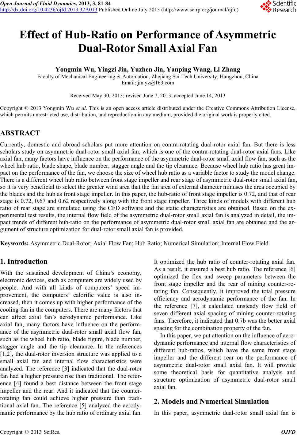 Open Journal of Fluid Dynamics, 2013, 3, 81-84 http://dx.doi.org/10.4236/ojfd.2013.32A013 Published Online July 2013 (http://www.scirp.org/journal/ojfd) Effect of Hub-Ratio on Performance of Asymmetric Dual-Rotor Small Axial Fan Yongmin Wu, Yingzi Jin, Yuzhen Jin, Yanping Wang, Li Zhang Faculty of Mechanical Engineering & Automation, Zhejiang Sci-Tech University, Hangzhou, China Email: jin.yz@163.com Received May 30, 2013; revised June 7, 2013; accepted June 14, 2013 Copyright © 2013 Yongmin Wu et al. This is an open access article distributed under the Creative Commons Attribution License, which permits unrestricted use, distribution, and reproduction in any medium, provided the original work is properly cited. ABSTRACT Currently, domestic and abroad scholars put more attention on contra-rotating dual-rotor axial fan. But there is less scholars study on asymmetric dual-rotor small axial fan, which is one of the contra-rotating dual-rotor axial fans. Like axial fan, many factors have influence on the performance of the asymmetric dual-rotor small axial flow fan, such as the wheel hub ratio, blade shape, blade number, stagger angle and the tip clearance. Because wheel hub ratio has great im- pact on the performance of the fan, we choose the size of wheel hub ratio as a variable factor to study the model change. There is a different wheel hub ratio between front stage impeller and rear stage of asymmetric dual-rotor small axial fan, so it is very beneficial to select the greater wind area that the fan area of external diameter minuses the area occupied by the blades and the hub as front stage impeller. In this paper, the hub-ratio of front stage impeller is 0.72, and that of rear stage is 0.72, 0.67 and 0.62 respectively along with the front stage impeller. Three kinds of models with different hub ratio of rear stage are simulated using the CFD software and the static characteristics are obtained. Based on the ex- perimental test results, the internal flow field of the asymmetric dual-rotor small axial fan is analyzed in detail, the im- pact trends of different hub-ratio on the performance of asymmetric dual-rotor small axial fan are obtained and the ar- gument of structure optimization for dual-rotor small axial fan is provided. Keywords: Asymmetric Dual-Rotor; Axial Flow Fan; Hub Ratio; Numerical Simulation; Internal Flow Field 1. Introduction With the sustained development of China’s economy, electronic devices, such as computers are widely used by people. And with all kinds of computers’ speed im- provement, the computers’ calorific value is also in- creased, then it comes up with higher performance of the cooling fan in the computers. There are many factors that can affect axial fan’s aerodynamic performance. Like axial fan, many factors have influence on the perform- ance of the asymmetric dual-rotor small axial flow fan, such as the wheel hub ratio, blade figure, blade number, stagger angle and the tip clearance. In the references [1,2], the dual-rotor inversion structure was applied to a small axial fan and internal flow characteristics were analyzed. The reference [3] indicated that the dual-rotor fan had a higher pressure rise than traditional. The refer- ence [4] found a best distance between the front stage impeller and the rear. And it indicated that the counter- rotating fan could achieve higher pressure than tradi- tional axial fan. The reference [5] analyzed the aerody- namic performance by the hub ratio of ordinary axial fan. It optimized the hub ratio of counter-rotating axial fan. As a result, it ensured a best hub ratio. The reference [6] optimized the flex and sweep parameters between the front stage impeller and the rear of mining counter-ro- tating fan. Consequently, it improved the total pressure efficiency and aerodynamic performance of the fan. In the reference [7], it calculated unsteady flow field of seven different axial spacing of mining counter-rotating fans. Therefore, it indicated that 0.7b was the better axial spacing for the combination property of the fan. In this paper, we put attention on the influence of aero- dynamic performance and internal flow characteristics of different hub-ratios, which have the same front stage impeller and the different rear on the performance of asymmetric dual-rotor small axial fan. It will provide some theoretical basis for quantitative analysis and structure optimization of asymmetric dual-rotor small axial fan. 2. Models and Numerical Simulation In this paper, asymmetric dual-rotor small axial fan is C opyright © 2013 SciRes. OJFD 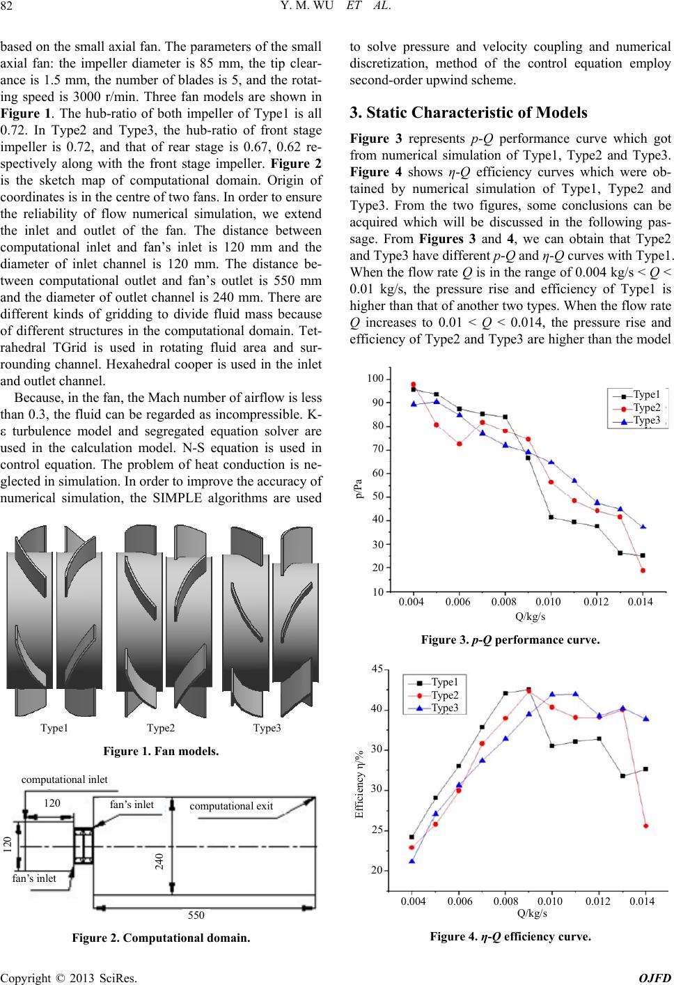 Y. M. WU ET AL. 82 based on the small axial fan. The parameters of the small axial fan: the impeller diameter is 85 mm, the tip clear- ance is 1.5 mm, the number of blades is 5, and the rotat- ing speed is 3000 r/min. Three fan models are shown in Figure 1. The hub-ratio of both impeller of Type1 is all 0.72. In Type2 and Type3, the hub-ratio of front stage impeller is 0.72, and that of rear stage is 0.67, 0.62 re- spectively along with the front stage impeller. Figure 2 is the sketch map of computational domain. Origin of coordinates is in the centre of two fans. In order to ensure the reliability of flow numerical simulation, we extend the inlet and outlet of the fan. The distance between computational inlet and fan’s inlet is 120 mm and the diameter of inlet channel is 120 mm. The distance be- tween computational outlet and fan’s outlet is 550 mm and the diameter of outlet channel is 240 mm. There are different kinds of gridding to divide fluid mass because of different structures in the computational domain. Tet- rahedral TGrid is used in rotating fluid area and sur- rounding channel. Hexahedral cooper is used in the inlet and outlet channel. Because, in the fan, the Mach number of airflow is less than 0.3, the fluid can be regarded as incompressible. K- ε turbulence model and segregated equation solver are used in the calculation model. N-S equation is used in control equation. The problem of heat conduction is ne- glected in simulation. In order to improve the accuracy of numerical simulation, the SIMPLE algorithms are used Type1 Type2 Type3 Figure 1. Fan models. computational inlet 550 fan’s inlet fan’s inlet computational exit 120 120 240 Figure 2. Computational domain. to solve pressure and velocity coupling and numerical discretization, method of the control equation employ second-order upwind scheme. 3. Static Characteristic of Models Figure 3 represents p-Q performance curve which got from numerical simulation of Type1, Type2 and Type3. Figure 4 shows η-Q efficiency curves which were ob- tained by numerical simulation of Type1, Type2 and Type3. From the two figures, some conclusions can be acquired which will be discussed in the following pas- sage. From Figures 3 and 4, we can obtain that Type2 and Type3 have different p-Q and η-Q curves with Type1. When the flow rate Q is in the range of 0.004 kg/s < Q < 0.01 kg/s, the pressure rise and efficiency of Type1 is higher than that of another two types. When the flow rate Q increases to 0.01 < Q < 0.014, the pressure rise and efficiency of Type2 and Type3 are higher than the model Type1 Type2 Type3 p/Pa 100 90 80 70 60 50 40 30 20 10 0.0040.0060.008 0.010 0.0120.014 Q/kg/s Figure 3. p-Q performance curve. Type1 Type2 T yp e3 45 40 30 20 0.0040.0060.008 0.010 0.0120.014 Q/kg/s 25 30 Efficiency η/% Figure 4. η-Q efficiency curve. Copyright © 2013 SciRes. OJFD 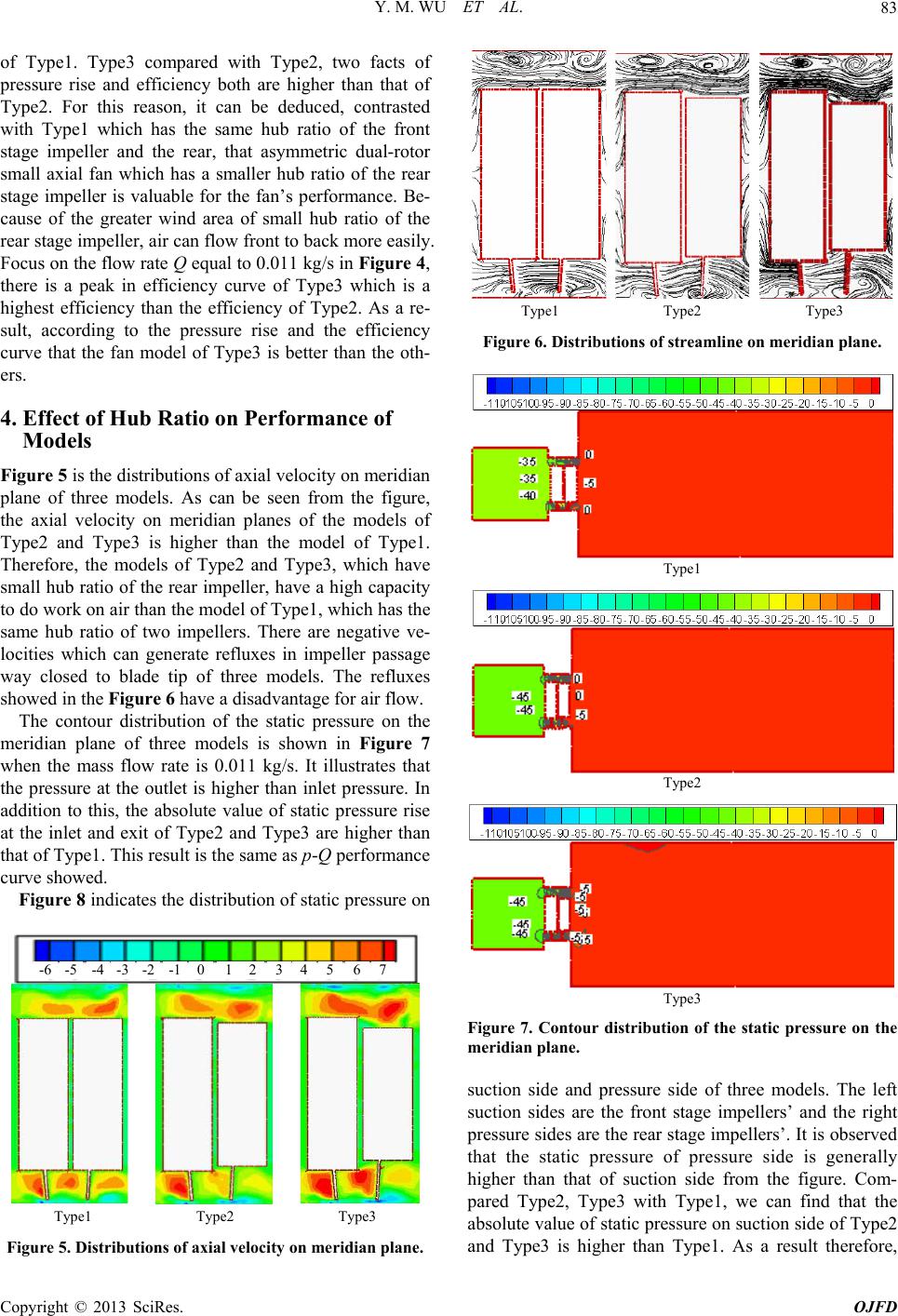 Y. M. WU ET AL. 83 of Type1. Type3 compared with Type2, two facts of pressure rise and efficiency both are higher than that of Type2. For this reason, it can be deduced, contrasted with Type1 which has the same hub ratio of the front stage impeller and the rear, that asymmetric dual-rotor small axial fan which has a smaller hub ratio of the rear stage impeller is valuable for the fan’s performance. Be- cause of the greater wind area of small hub ratio of the rear stage impeller, air can flow front to back more easily. Focus on the flow rate Q equal to 0.011 kg/s in Figure 4, there is a peak in efficiency curve of Type3 which is a highest efficiency than the efficiency of Type2. As a re- sult, according to the pressure rise and the efficiency curve that the fan model of Type3 is better than the oth- ers. 4. Effect of Hub Ratio on Performance of Models Figure 5 is the distributions of axial velocity on meridian plane of three models. As can be seen from the figure, the axial velocity on meridian planes of the models of Type2 and Type3 is higher than the model of Type1. Therefore, the models of Type2 and Type3, which have small hub ratio of the rear impeller, have a high capacity to do work on air than the model of Type1, which has the same hub ratio of two impellers. There are negative ve- locities which can generate refluxes in impeller passage way closed to blade tip of three models. The refluxes showed in the Figure 6 have a disadvantage for air flow. The contour distribution of the static pressure on the meridian plane of three models is shown in Figure 7 when the mass flow rate is 0.011 kg/s. It illustrates that the pressure at the outlet is higher than inlet pressure. In addition to this, the absolute value of static pressure rise at the inlet and exit of Type2 and Type3 are higher than that of Type1. This result is the same as p-Q performance curve showed. Figure 8 indicates the distribution of static pressure on -6 -5 -4 -3 -2 -1 0 12 3 4 5 6 7 Type1 Type2 Type3 Figure 5. Distributions of axial velocity on meridian plane. Type1 Type2 Type3 Figure 6. Distributions of streamline on meridian plane. Type1 Type2 Type3 Figure 7. Contour distribution of the static pressure on the meridian plane. suction side and pressure side of three models. The left suction sides are the front stage impellers’ and the right pressure sides are the rear stage impellers’. It is observed that the static pressure of pressure side is generally higher than that of suction side from the figure. Com- pared Type2, Type3 with Type1, we can find that the absolute value of static pressure on suction side of Type2 and Type3 is higher than Type1. As a result therefore, Copyright © 2013 SciRes. OJFD 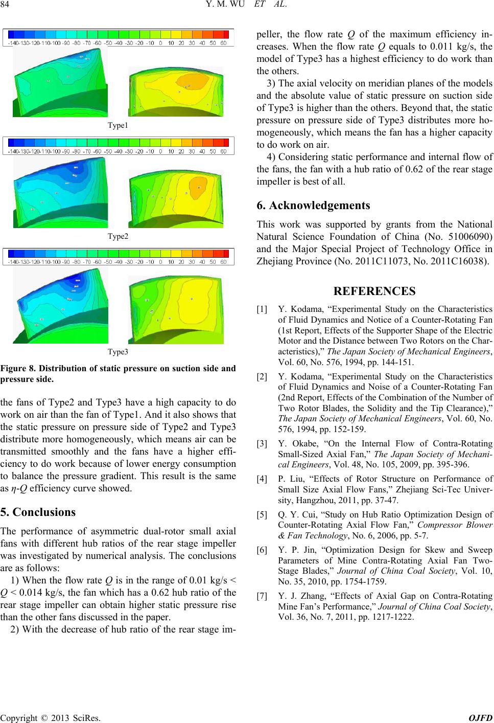 Y. M. WU ET AL. Copyright © 2013 SciRes. OJFD 84 Type1 Type2 Type3 Figure 8. Distribution of static pr essure on suction side and pressure side. the fans of Type2 and Type3 have a high capacity to do work on air than the fan of Type1. And it also shows that the static pressure on pressure side of Type2 and Type3 distribute more homogeneously, which means air can be transmitted smoothly and the fans have a higher effi- ciency to do work because of lower energy consumption to balance the pressure gradient. This result is the same as η-Q efficiency curve showed. 5. Conclusions The performance of asymmetric dual-rotor small axial fans with different hub ratios of the rear stage impeller was investigated by numerical analysis. The conclusions are as follows: 1) When the flow rate Q is in the range of 0.01 kg/s < Q < 0.014 kg/s, the fan which has a 0.62 hub ratio of the rear stage impeller can obtain higher static pressure rise than the other fans discussed in the paper. 2) With the decrease of hub ratio of the rear stage im- peller, the flow rate Q of the maximum efficiency in- creases. When the flow rate Q equals to 0.011 kg/s, the model of Type3 has a highest efficiency to do work than the others. 3) The axial velocity on meridian planes of the models and the absolute value of static pressure on suction side of Type3 is higher than the others. Beyond that, the static pressure on pressure side of Type3 distributes more ho- mogeneously, which means the fan has a higher capacity to do work on air. 4) Considering static performance and internal flow of the fans, the fan with a hub ratio of 0.62 of the rear stage impeller is best of all. 6. Acknowledgements This work was supported by grants from the National Natural Science Foundation of China (No. 51006090) and the Major Special Project of Technology Office in Zhejiang Province (No. 2011C11073, No. 2011C16038). REFERENCES [1] Y. Kodama, “Experimental Study on the Characteristics of Fluid Dynamics and Notice of a Counter-Rotating Fan (1st Report, Effects of the Supporter Shape of the Electric Motor and the Distance between Two Rotors on the Char- acteristics),” The Japan Society of Mechanical Engineers, Vol. 60, No. 576, 1994, pp. 144-151. [2] Y. Kodama, “Experimental Study on the Characteristics of Fluid Dynamics and Noise of a Counter-Rotating Fan (2nd Report, Effects of the Combination of the Number of Two Rotor Blades, the Solidity and the Tip Clearance),” The Japan Society of Mechanical Engineers, Vol. 60, No. 576, 1994, pp. 152-159. [3] Y. Okabe, “On the Internal Flow of Contra-Rotating Small-Sized Axial Fan,” The Japan Society of Mechani- cal Engineers, Vol. 48, No. 105, 2009, pp. 395-396. [4] P. Liu, “Effects of Rotor Structure on Performance of Small Size Axial Flow Fans,” Zhejiang Sci-Tec Univer- sity, Hangzhou, 2011, pp. 37-47. [5] Q. Y. Cui, “Study on Hub Ratio Optimization Design of Counter-Rotating Axial Flow Fan,” Compressor Blower & Fan Technology, No. 6, 2006, pp. 5-7. [6] Y. P. Jin, “Optimization Design for Skew and Sweep Parameters of Mine Contra-Rotating Axial Fan Two- Stage Blades,” Journal of China Coal Society, Vol. 10, No. 35, 2010, pp. 1754-1759. [7] Y. J. Zhang, “Effects of Axial Gap on Contra-Rotating Mine Fan’s Performance,” Journal of China Coal Society, Vol. 36, No. 7, 2011, pp. 1217-1222. |