Paper Menu >>
Journal Menu >>
 Open Journal of Fluid Dynamics, 2013, 3, 75-80 http://dx.doi.org/10.4236/ojfd.2013.32A012 Published Online July 2013 (http://www.scirp.org/journal/ojfd) Numerical Study on Internal Flow of Small Axial Flow Fan with Splitter Blades Lifu Zhu, Yingzi Jin*, Yuzhen Jin, Yanping Wang, Li Zhang The Province Key Laboratory of Fluid Transmission Technology, Zhejiang Sci-Tech University, Hangzhou, China Email: *jin.yz@163.com Received May 30, 2013; revised June 7, 2013; accepted June 14, 2013 Copyright © 2013 Lifu Zhu et al. This is an open access article distributed under the Creative Commons Attribution License, which permits unrestricted use, distribution, and reproduction in any medium, provided the original work is properly cited. ABSTRACT The splitter blades are widely used in axial compressors and play an active role in the improvement of the overall per- formance of compressors. However, little research on the application of splitter blades to small axial flow fans is con- ducted. This paper designs a splitter blade small axial flow fan (model B) with a small axial flow fan as the prototype fan (model A) by adding short blades at the second half part of the passageway among long blades of model A. The steady simulation for the two models was conducted with the help of RNG k-ε turbulence model provided by software Fluent, and static characteristics and internal flow characteristics of the two models were compared and analyzed. Re- sults show that splitter blades can improve the unsteady flow in the small flow rate region and also have a positive role to increase static pressure rise and efficiency in the higher flow rate region. The variation of static pressure gradient on the meridian plane in model B is well-distributed. The static pressure on the blade surface of model B distributes more uniformly. Splitter blades can suppress the secondary flow from pressure side to suction side in the leading edge be- cause the pressure difference between suction side and pressure side in model B is generally lower than that of model A. And it also can restrain the vortex shedding and flow separation, and further it may be able to get the aerodynamic noise lower because static pressure gradient on the blade surface is well-distributed and the vortex shedding is not developed. Therefore, the performance of the fan with splitter blades is better than that of the prototype fan. The findings of this paper can be a basis for the design of high performance small axial flow fans. Keywords: Small Axial Flow Fan; Splitter Blade; Internal Flow; Performance 1. Introduction The technology of splitter blade is adding short blades at the passageway among the original long blades of impel- lers, and the splitter blade is known as short blade or small blade. The short blades and long blades are alterna- tive arrangements, which can improve the distribution of the internal flow field of impellers; what’s more, it also can increase the load of blades and pressure ratio of im- pellers, it is an effective method to improve the overall performance of impellers [1]. The technology of splitter blade is widely used in centrifugal impellers, and then the research and application in the axial impellers are starting lately. In 1974, Wennerstrom [2,3] applied the technology of splitter blade in the axial compressors, he decreased the deviation angle of outlet airflow in the high load rotor by changing the aerodynamic arrangement. Because of being limited by the methods of numerical simulation and experiment at that moment, the applica- tion of splitter blades to the axial impellers was not suc- cessful and this technology was stalled. Since 1980s, with the development of computer and methods of full three-dimensional numerical simulation, the technology of splitter blade was applied again and it had obtained the significant achievements [4-6]. Tzuoo et al. [7] reviewed the results of a detailed analytical study performed on Wennerstrom’s rotor, followed by the details of a redes- ign effort using advanced design methodology, and the results showed that the extensive flow separation ob- served in Wennerstrom’s rotor can be completely elimi- nated by redesigning the main blade and splitter vane. Yongxin Zhang et al. [8] found that splitter could recon- struct the balance of pressure in rotor passage, and con- trolled the flow near rotor blade. Ming Yan et al. [9] studied flow characteristics of one axial compressor rotor with splitter, they concluded that the rotor with splitter could be operated with higher total pressure ratio, higher efficiency and larger mass flow than normal designed rotors, under the high loaded condition and with the same *Corresponding author. C opyright © 2013 SciRes. OJFD 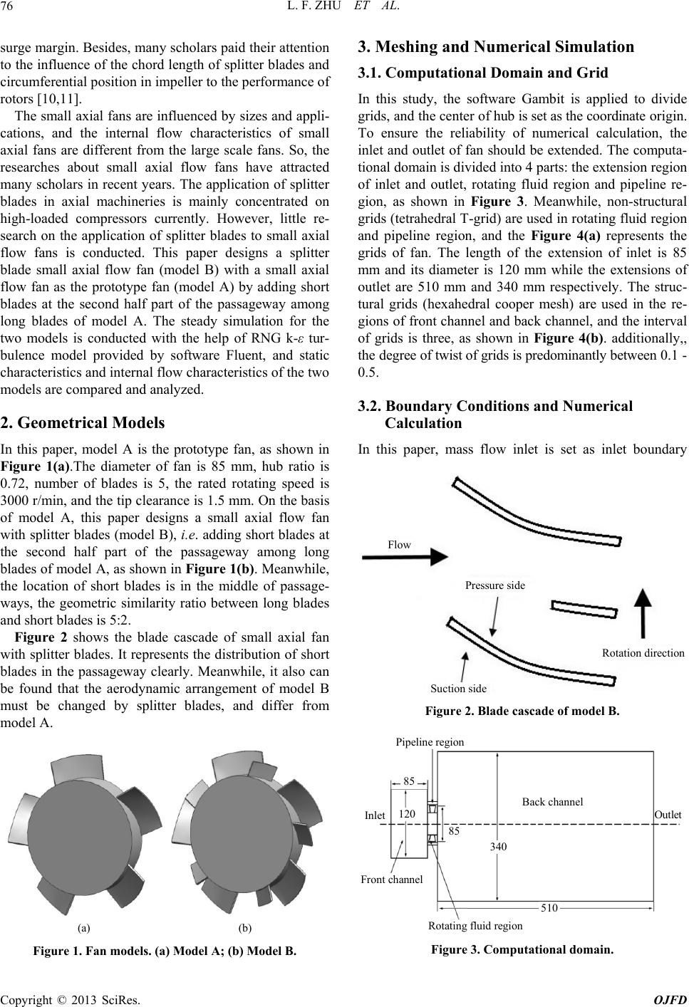 L. F. ZHU ET AL. 76 surge margin. Besides, many scholars paid their attention to the influence of the chord length of splitter blades and circumferential position in impeller to the performance of rotors [10,11]. The small axial fans are influenced by sizes and appli- cations, and the internal flow characteristics of small axial fans are different from the large scale fans. So, the researches about small axial flow fans have attracted many scholars in recent years. The application of splitter blades in axial machineries is mainly concentrated on high-loaded compressors currently. However, little re- search on the application of splitter blades to small axial flow fans is conducted. This paper designs a splitter blade small axial flow fan (model B) with a small axial flow fan as the prototype fan (model A) by adding short blades at the second half part of the passageway among long blades of model A. The steady simulation for the two models is conducted with the help of RNG k-ε tur- bulence model provided by software Fluent, and static characteristics and internal flow characteristics of the two models are compared and analyzed. 2. Geometrical Models In this paper, model A is the prototype fan, as shown in Figure 1(a).The diameter of fan is 85 mm, hub ratio is 0.72, number of blades is 5, the rated rotating speed is 3000 r/min, and the tip clearance is 1.5 mm. On the basis of model A, this paper designs a small axial flow fan with splitter blades (model B), i.e. adding short blades at the second half part of the passageway among long blades of model A, as shown in Figure 1(b). Meanwhile, the location of short blades is in the middle of passage- ways, the geometric similarity ratio between long blades and short blades is 5:2. Figure 2 shows the blade cascade of small axial fan with splitter blades. It represents the distribution of short blades in the passageway clearly. Meanwhile, it also can be found that the aerodynamic arrangement of model B must be changed by splitter blades, and differ from model A. (a) (b) Figure 1. Fan models. (a) Model A; (b) Model B. 3. Meshing and Numerical Simulation 3.1. Computational Domain and Grid In this study, the software Gambit is applied to divide grids, and the center of hub is set as the coordinate origin. To ensure the reliability of numerical calculation, the inlet and outlet of fan should be extended. The computa- tional domain is divided into 4 parts: the extension region of inlet and outlet, rotating fluid region and pipeline re- gion, as shown in Figure 3. Meanwhile, non-structural grids (tetrahedral T-grid) are used in rotating fluid region and pipeline region, and the Figure 4(a) represents the grids of fan. The length of the extension of inlet is 85 mm and its diameter is 120 mm while the extensions of outlet are 510 mm and 340 mm respectively. The struc- tural grids (hexahedral cooper mesh) are used in the re- gions of front channel and back channel, and the interval of grids is three, as shown in Figure 4(b). additionally,, the degree of twist of grids is predominantly between 0.1 - 0.5. 3.2. Boundary Conditions and Numerical Calculation In this paper, mass flow inlet is set as inlet boundary Pressure side Suctio n side Rotation directio n Flow Figure 2. Blade cascade of model B. Pipeline region Rotating fluid region Front channel Inlet Outlet Back channel 340 510 85 85 120 Figure 3. Computational domain. Copyright © 2013 SciRes. OJFD  L. F. ZHU ET AL. 77 (a) (b) Figure 4. Computational grids. (a) Girds of fan; (b) Girds of the extension of inlet and outlet. condition, while, the outlet boundary condition is pres- sure outlet. The solid walls such as vane surfaces and hub satisfy the no-slip condition in the computational do- main. The finite volume method is carried out in numerical calculation. It is assumed that the flow field of the im- peller is incompressible and inviscid. The steady simula- tion for the two models is conducted with the help of RNG k-ε turbulence model provided by software Fluent. Meanwhile, second order upwind difference scheme is adopted as numerical discretization method of governing equation. The residuals are equal or less than the given standard (10−3), and relative error of flow rate at the inlet as well as outlet is less than 0.5%, then the calculation is convergence. 4. Results and Discussions 4.1. Static Characteristics of Models The static characteristics are an important factor to ana- lyze the performance of small axial fan. Meanwhile, the static characteristics are reflected by the P-Q and the η- Q performance curves in general, where P is static pres- sure and η is efficiency. In this research, the different inlet flow rates are set, and the steady flow fields of fans are got in 21 flow-rate conditions from Q = 0.002 kg/s to Q = 0.012 kg/s at the flow-rate interval of Q = 0.0005 kg/s. Figures 5 and 6 represent P-Q and η-Q performance curves obtained from steady simulation of two models. Figure 5. Performance curve of flow rate and static pres- sure. Figure 6. Performance curve of flow rate and efficiency. From Figure 5, it can be seen that the static pressure rise at the inlet and outlet of the two models decrease with the increase of inlet flow rate Q on the whole. In addition to this, when the inlet flow rate Q is less than 0.045 kg/s, fans are working under the small flow rate at the moment, so the flow is unsteady. For this reason, the curve of model A have a concave region, nevertheless, this phenomenon does not appear in model B. Thus it can be concluded that splitter blades can improve the un- steady flow in the small flow rate region. When the inlet flow rate Q > 0.045 kg/s, the static pressure rise of model B is always higher than that of model A. Hence, splitter blades have a positive role to increase the static pressure rise. Figure 6 shows the η-Q curves of two models. It is found that the efficiency of the two models are closely similar while 0.002 kg/s < Q < 0.006 kg/s, when Q > 0.006 kg/s, the efficiency of model B is notably higher Copyright © 2013 SciRes. OJFD 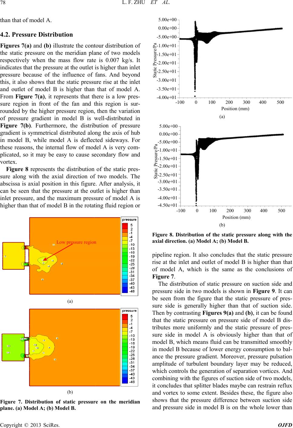 L. F. ZHU ET AL. 78 than that of model A. 4.2. Pressure Distribution Figures 7(a) and (b) illustrate the contour distribution of the static pressure on the meridian plane of two models respectively when the mass flow rate is 0.007 kg/s. It indicates that the pressure at the outlet is higher than inlet pressure because of the influence of fans. And beyond this, it also shows that the static pressure rise at the inlet and outlet of model B is higher than that of model A. From Figure 7(a), it represents that there is a low pres- sure region in front of the fan and this region is sur- rounded by the higher pressure region, then the variation of pressure gradient in model B is well-distributed in Figure 7(b). Furthermore, the distribution of pressure gradient is symmetrical distributed along the axis of hub in model B, while model A is deflected sideways. For these reasons, the internal flow of model A is very com- plicated, so it may be easy to cause secondary flow and vortex. Figure 8 represents the distribution of the static pres- sure along with the axial direction of two models. The abscissa is axial position in this figure. After analysis, it can be seen that the pressure at the outlet is higher than inlet pressure, and the maximum pressure of model A is higher than that of model B in the rotating fluid region or Low pressure region (a) (b) Figure 7. Distribution of static pressure on the meridian plane. (a) Model A; (b) Model B. 5.00e+00 0.00e+00 -5.00e+00 Static Pressure/Pa -1.00e+01 -1.50e+01 -2.00e+01 -2.50e+01 -3.00e+01 -3.50e+01 -4.00e+01 -100 100200 300 4005000 Position (mm) (a) 5.00e+00 0.00e+00 Static Pressure/Pa -1.00 e+01 -1.50 e+01 -2.00 e+01 -2.50 e+01 -3.00 e+01 -3.50 e+01 -4.00 e+01 -100 100200 300 400 5000 Position (mm) -4.50 e+01 -5.00 e+00 (b) Figure 8. Distribution of thwith the ipeline region. It also concludes that the static pressure ribution of static pressure on suction side and pr e static pressure along axial direction. (a) Model A; (b) Model B. p rise at the inlet and outlet of model B is higher than that of model A, which is the same as the conclusions of Figure 7. The dist essure side in two models is shown in Figure 9. It can be seen from the figure that the static pressure of pres- sure side is generally higher than that of suction side. Then by contrasting Figures 9(a) and (b), it can be found that the static pressure on pressure side of model B dis- tributes more uniformly and the static pressure of pres- sure side in model A is obviously higher than that of model B, which means fluid can be transmitted smoothly in model B because of lower energy consumption to bal- ance the pressure gradient. Moreover, pressure pulsation amplitude of turbulent boundary layer may be reduced, which controls the generation of separation vortices. And combining with the figures of suction side of two models, it concludes that splitter blades maybe can restrain reflux and vortex to some extent. Besides these, the figure also shows that the pressure difference between suction side and pressure side in model B is on the whole lower than Copyright © 2013 SciRes. OJFD 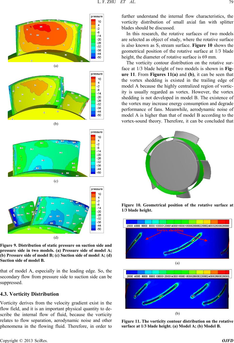 L. F. ZHU ET AL. 79 (a) (b) (c) (d) Figure 9. Distribution of staticessure on suction side and surfaces of two models ar ve sur- fa pr pressure side in two models. (a) Pressure side of model A; (b) P r es s ur e s i de of model B; (c) Suc tion side of model A ; ( d) Suction side of model B. that of model A, especially in the leading edge. So, the secondary flow from pressure side to suction side can be suppressed. 4.3. Vorticity Distribution Vorticity derives from the velocity gradient exist in the flow field, and it is an important physical quantity to de- scribe the internal flow of fluid, because the vorticity relates to flow separation, aerodynamic noise and other phenomena in the flowing fluid. Therefore, in order to further understand the internal flow characteristics, the vorticity distribution of small axial fan with splitter blades should be discussed. In this research, the rotative e selected as object of study, where the rotative surface is also known as S1 stream surface. Figure 10 shows the geometrical position of the rotative surface at 1/3 blade height, the diameter of rotative surface is 69 mm. The vorticity contour distribution on the rotati ce at 1/3 blade height of two models is shown in Fig- ure 11. From Figures 11(a) and (b), it can be seen that the vortex shedding is existed in the trailing edge of model A because the highly centralized region of vortic- ity is usually regarded as vortex. However, the vortex shedding is not developed in model B. The existence of the vortex may increase energy consumption and degrade performance of fans. Meanwhile, aerodynamic noise of model A is higher than that of model B according to the vortex-sound theory. Therefore, it can be concluded that Figure 10. Geometrical position of the rotative surface at 1/3 blade height. Vortex shedding (a) (b) Figure 11. The vorticity con distribution on the rotative tour surface at 1/3 blade height. (a) Model A; (b) Model B. Copyright © 2013 SciRes. OJFD  L. F. ZHU ET AL. Copyright © 2013 SciRes. OJFD 80 hed- all axial fan with splitter blades. e unsteady flow of sm transmitted smoothly in the small axial fa shedding and flo ants from the National splitter blades may be able to suppress the vortex s ding and flow separation, and then improve the perform- ance of fans to some extent, such as static characteristics and aerodynamic noise. 5. Conclusions The paper designs a sm With the help of the numerical simulation, the influence of splitter blades on the performance of small axial fan is investigated. The static characteristics of models are rep- resented, and the internal flow characteristics are dis- cussed from two aspects, i.e. pressure and vorticity. The conclusions are shown as followed: 1) Splitter blades can improve th [4] all axial flow fan in the small flow rate region. When the inlet flow rate Q > 0.045 kg/s, the static pressure rise of model B is obviously higher than that of model A, and the efficiencies of the two models are closely similar while 0.002 kg/s < Q < 0.006 kg/s; when Q > 0.006 kg/s, the efficiency of model B is notably higher than that of model A. So, splitter blades have a positive role to in- crease the static pressure rise and efficiency in the higher flow rate region. 2) Fluid can be [7] n with splitter blades, because the static pressure dis- tributes more uniformly. And pressure pulsation ampli- tude of turbulent boundary layer may be reduced, which controls the generation of separation vortices. Splitter blades can suppress the secondary flow from pressure side to suction side in the leading edge. 3) Splitter blades can restrain the vortex w separation, and further it may be able to get the aerodynamic noise lower because static pressure gradient on the blade surface is well-distributed and the vortex shedding is not developed. 6. Acknowledgements This work was supported by gr [11] Natural Science Foundation of China (No. 51006090) and the Major Special Project of Technology Office in Zhejiang Province (No. 2011C11073, No. 2011C16038). REFERENCES [1] J. F. Zhang, Y Yuan, L. T. Ye, et al., “Research State of The Centrifugal Machineries with Impeller Adding Split- ter Blades,” Fluid Machinery, Vol. 39, No. 11, 2011, pp. 38-44. [2] A. J. Wennerstrom and G. R. Frost, “Design of a Rotor Incorporating Splitter Vanes for a High Pressure Ratio Supersonic Axial Compressor Stage,” United States Air Force Systems Command, ARL-TR-74-0110, 1974. [3] A. J. Wennerstrom, “Test of a Supersonic Axial Com- pressor Stage Incorporating Splitter Vanes in The Rotor,” United States Air Force Systems Command, ARL-TR- 75-0165, 1975. X. Qiu and T. Dang, “Three-Dimension Inverse Method for Turbomachine Blading with Splitter Blades,” ASME Paper, 2000-GT-0526, 2000. [5] H. P. Li and H. X. Liu, “Numerical Simulation Analysis of Leakage Flow in Compressor Cascade with Splitter,” Journal of Beijing University of Aeronautics and Astro- nautics, Vol. 33, No. 1, 2007, pp. 31-34. [6] H. P. Li and H. X. Liu, “Analysis of Flow Mechanism in 2-D Compressor Cascade with Splitter,” ASME Paper, GT-2005-68207, 2005. K. L. Tzuoo, S. S. Hingorani and A. K. Sehra, “Optimiza- tion of a Highly-Loaded Axial Splittered Rotor Design,” Revue Francaise de Mecanique, Vol. 1, No. 3, 1992, pp. 235-246. [8] Y. X. Zhang, Z. P. Zou, M. Yan and M. Z. Chen, “Flow Analysis of a Single-Stage Axial Flow Compressor with Splitter Rotor,” Journal of Aerospace Power, Vol. 19, No. 1, 2004, pp. 89-93. [9] M. Yan and M. Z. Chen, “Flow Performance Analysis in an Axial Compressor Rotor with Splitter,” Journal of Propulsion Technology, Vol. 24, No. 4, 2002, pp. 280- 282. [10] X. M. Sun, P. G. Yan, S. T. Wang and Q. Zhong, “Inves- tigation of the Influence of Splitter Chord Length on the Transonic Axial Fan Rotor,” Journal of Aerospace Power, Vol. 22, No. 12, 2007, pp. 2050-2054. L. Xue and W. J. Han, “Effects of Circumferential Con- figuration Concerning Splitter Blade on the Aerodynamic Performance in a Transonic Axial Fan,” Journal of Har- bin Institute of Technology, Vol. 17, No. 1, 2010, pp. 75- 81. |

