Open Journal of Fluid Dynamics, 2013, 3, 36-41
http://dx.doi.org/10.4236/ojfd.2013.32A006 Published Online July 2013 (http://www.scirp.org/journal/ojfd)
Wells Turbine for Wave Energy Conversion
—Improvement of the Perfo r m a nce by Means of Impulse Turbine for Bi - D irectional Flow
Shinya Okuhara1, Manabu Takao2, Akiyasu Takami2, Toshiaki Setoguchi3
1Techno Center, Matsue College of Technology, Matsue, Japan
2Department of Mechanical Engineering, Matsue College of Technology, Matsue, Japan
3Institute of Ocean Energy, Saga University, Saga, Japan
Email: takao@matsue-ct.jp
Received May 29, 2013; revised June 6, 2013; accepted June 13, 2013
Copyright © 2013 Shinya Okuhara et al. This is an open access article distributed under the Creative Commons Attribution License,
which permits unrestricted use, distribution, and reproduction in any medium, provided the original work is properly cited.
ABSTRACT
Wells turbine has inherent disadvantages in comparison with conventional turbines: relative low efficiency at high flow
coefficient and poor starting characteristics. To solve these problems, the authors propose Wells turbine with booster
turbine for wave energy conversion, in order to improve the performance in this study. This turbine consists of three
parts: a large Wells turbine, a small impulse turbine with fixed guide vanes for oscillating airflow, and a generator. It
was conjectured that, by coupling the two axial flow turbines together, pneumatic energy from oscillating airflow is
captured by Wells turbine at low flow coefficient and that the impulse turbine gets the energy at high flow coefficient.
As the first step of this study on the proposed turbine topology, the performance of turbines under steady flow condi-
tions has been investigated experimentally by model testings. Furthermore, we estimate mean efficiency of the turbine
by quasi-steady analysis.
Keywords: Fluid Machinery; Wells Turbine; Impulse Turbine; Wave Energy Conversion; Ocean Engineering
1. Introduction
Several of the wave energy devices being studied under
many wave energy programs in the United Kingdom,
Japan, Portugal, India and other countries make use of
the principle of an oscillating water column (OWC) [1].
In such wave energy devices, a water column which os-
cillates due to wave motion is used to drive an oscillating
air column which is converted into mechanical energy.
The energy conversion from the oscillating air column
can be achieved by using a self-rectifying air turbine
such as Wells turbine which was introduced by Dr. A. A.
Wells in 1976 [2-6]. Figure 1 shows outline of Wells
turbine. This turbine rotates in a single direction in oscil-
lating airflow and therefore does not require a system of
non-return valves. Furthermore, this turbine is one of the
simplest and probably the most economical turbines for
wave energy conversion. However, according to previous
studies, Wells turbine has inherent disadvantages: low
efficiency at high flow coefficient and poor starting
characteristics in comparison with conventional turbines
because of a severe stall [2-6]. Therefore, although a
number of OWC based wave energy plants using Wells
turbine have been constructed and tested to date, the total
conversion efficiencies of the plants were approximately
15% at the best [7-9]. Moreover, Wells turbine has high
noise level and maintenance problem because of high
rotational speed.
Recently, in order to develop a high performance self-
rectifying air turbine for wave energy conversion, an
impulse turbine for bi-directional flow has been proposed
by the authors [10-12]. Figure 2 shows outline of the
impulse turbine. There are many reports which describe
the performance of the impulse turbine both at starting
and running conditions. The experimental results of the
model testing show that the efficiency of the impulse
turbine is high in a wide range of flow coefficient, though
its peak efficiency is almost the same as that of Wells
turbine [10-12].
The authors propose Wells turbine with booster tur-
bine in this study. An impulse turbine for bi-directional
flow is used as the booster turbine in order to improve
the efficiency of Wells turbine at high flow coefficient.
This turbine consists of a large Wells turbine, a small
impulse turbine and a generator, as shown in Figure 3. It
was conjectured that by coupling the two turbines together,
pneumatic energy from oscillating airflow is captured by
C
opyright © 2013 SciRes. OJFD
S. OKUHARA ET AL. 37
Rotation
Casing
Generator
Oscilla t in g
airflow
Wells
turbi ne
Oscilla t in g
airflow
Hub
Figure 1. Outline of wells turbine.
Rotation
Guide vane
Rot or
Guide vane
Airf low
Airf low
θ
θ
Figure 2. Outline of impulse turbine for wave energy con-
version.
Generator
OWC
(Oscillating Water Column)
Air chamber
Impulse turbine T
i
(booster turbine)
Wells turbine T
w
(main turbine)
Airflow Airflow
D
w
D
i
D
0
A
0
A
w
A
i
Duct
Figure 3. Principle of plant using Wells turbine with booster
turbine.
Wells turbine at low flow coefficient and the impulse
turbine gets the energy at high flow coefficient. As the
first step of study on the proposed turbine topology, the
performance of turbines under steady flow conditions
have been investigated experimentally by model testing.
Further, mean efficiency of the proposed turbine for
wave energy conversion has been estimated by quasi-
steady analysis in this study.
2. Experimental Apparatus and Procedure
A schematic view of the test rig is shown in Figure 4.
The test rig consists of a large piston-cylinder (diameter:
1.4 m, length: 1.7 m), one end of which is followed by a
settling chamber. Turbine testing is done in 300 mm di-
ameter test section with bell-mouthed entry/exit at both
its ends. The piston can be driven back and forth inside
the cylinder by means of three ball-screws through three
nuts fixed to the piston. All three screws are driven in
unison by a D.C. servo-motor through chain and sprock-
ets. A computer controls the motor, and hence the piston
velocity to produce any flow velocity. The test turbine is
coupled to a servo-motor/generator through a torque
transducer. The motor/generator is electrically controlled
such that the turbine shaft angular velocity is held con-
stant at any set value. The overall performance was
evaluated by the turbine output torque To, the flow rate Q,
the total pressure drop across the turbine Δp, and the tur-
bine angular velocity ω. The flow rate through the tur-
bine Q, whether it is inhalation (i.e., flow from atmos-
phere into the settling chamber) or exhalation (i.e., flow
from settling chamber to atmosphere), is calculated by
measuring the motion of piston, where the value of Q
agrees with that obtained by a Pitot tube survey. Tests
were performed with the flow rates up to 0.320 m3/s and
the turbine angular velocities up to 471 rad/s. The Rey-
nolds number based on the blade chord was approxi-
mately equal to 2.5 × 10⁵ for Wells turbine and 0.5 × 10⁵.
1 Wind tunnel
2 Piston
3 Ball-screw
4 Servomotor
5 D/A converter
6 Servo-pack
PC
1
2
3
4
56
89
10
11
12
7
7 Settling chamber
8 Turbine
9 Torque transducer
10 Servomotor-generator
11 Pressure transducer
12 A/D converter
Figure 4. Experimental apparatus and measuring sy ste m.
Copyright © 2013 SciRes. OJFD
S. OKUHARA ET AL.
38
The uncertainty of efficiency is about ±1%. This uncer-
tainty has been obtained by taking into account the dis-
persions in the measurement of the physical parameters
from which efficiency is obtained.
3. Tested Axial Turbines
Wells turbine adopted in the experiments is shown in
Figure 5. The detail of tested Wells turbine in the case of
casing diameter DW = 300 mm is as follows. The chord
length, l = 90 mm; blade profile, NACA0020; number of
blades, 6; solidity at mean radius, 0.67; hub-to-tip ratio, ν
= 0.7; aspect ratio, 0.5; tip diameter, 299 mm; tip clear-
ance, 0.5 mm; mean radius, rW = DW(1 + ν)/4 = 127.5
mm; width of flow passage, 45 mm. Note that the
adopted turbine rotor is the most promising one in pre-
vious studies [3,5,6].
As shown in Figure 6, the turbine configuration em-
ployed in the study is an impulse type having fixed guide
vanes both upstream and downstream, and these geome-
tries are symmetrical with respect to the rotor centerline.
The specifications of the impulse turbine rotor in the case
of casing diameter Di = 300 mm are as follows. The rotor
blade profile consists of a circular arc on the pressure
side and part of an ellipse on the suction side. A radius of
the circular is 30.2 mm and the ellipse has semi-major
axis of 125.8 mm and semi-minor axis of 41.4 mm. The
chord length is 54 mm; solidity of 2.02 at mean radius;
blade inlet (or outlet) angle of 60˚; thickness ratio of
0.298; tip diameter of 299 mm; hub-to-tip ratio of ν = 0.7;
tip clearance of 0.5 mm; mean radius, ri = Di(1 + ν)/4 =
127.5 mm. The guide vane with chord length of 70 mm
are symmetrically installed at the distance of 10 mm
0.65l0.35l
l= 90
45
210
300
Casing
Rotation
Blade
Hub
Unit: mm
NACA0020
0.5
Figure 5. Tested Wells turbine (DW = 300 mm).
16.1
125.8
41.4
54
R30.2
60
o
60
o
R0.5
10.6
26.7
R0.5
Unit : mm
34.8
70
0.5
10
10
34.8
70
30.8
Ro t or
Guide vane
Guide vane
30.8
37.2
60o
30o
30o
0.5
60o
37.2
Figure 6. Tested impulse turbine (Di = 300 mm).
downstream and upstream of the rotor (Figure 6). De-
tailed information about the guide vane is as follows:
solidity of 2.27 at mean radius; thickness ratio of 0.0071;
a guide vane setting angle of 30˚; camber angle of 60˚.
The camber line of guide vane consists of a straight line
with a length of 34.8 mm and a circular arc with a radius
of 37.2 mm. The rotor blade and guide vane are also the
most promising one [10-12].
4. Experimental Results
The turbine performance under steady flow conditions
evaluated by turbine efficiency
, torque coefficient CT
and input coefficient CA against flow coefficient
. The
definitions of these parameters are as follows:
22
To 2CTrvuAr (1)


22
A
22
2
2
CpQvuAv
pvu
 
  (2)

oT
TpQCC
A

 (3)
Copyright © 2013 SciRes. OJFD
S. OKUHARA ET AL. 39
vu
(4)
where A, u, v and
denote the flow passage area

22
π1D

4
i
p
, circumferential velocity at mean
radius {= rω}, axial flow velocity {= Q/A} and density
of air, respectively.
Figure 7 shows the experimental results of Wells tur-
bine and the impulse turbine. The torque coefficients CT
of both turbines increase with the flow coefficient
in
the region of low flow coefficient (Figure 7(a)). How-
ever, CT in the case of Wells turbine drops rapidly at
=
0.34 because of stall and it increases with flow coeffi-
cient after the stall point again. CT of the impulse turbine
slightly increases in the region of low flow coefficient.
However, CT of the impulse turbine is considerably
higher than that of Wells turbine after the stall point of
Wells turbine. Similarly, the input coefficients CA of the
turbines also increase
and CA of Wells turbine slightly
decreases at the stall point (Figure 7(b)). CA of the im-
pulse turbine increases with flow coefficient. But CA of
the impulse turbine leveled off after the flow coefficient
= 1.3. As shown in Figure 7(c), the efficiency of Wells
turbine is higher than that of the impulse turbine when
is less than the stall point. But after the stall point of
Wells turbine, the efficiency of impulse turbine is con-
siderably higher than that of Wells turbine and the effi-
ciency of Wells turbine is less than 0.04. The peak effi-
ciencies are almost the same and its value is approxi-
mately 0.48.
5. Estimation Method of Turbine
Characteristics under Sinusoidal Airflow
Conditions
Since the airflow into the turbine is generated by the
OWC, it is very important to demonstrate the turbine
characteristics under oscillating flow conditions. Here let
us simulate the characteristics under sinusoidal flow
conditions (Figure 8) in order to clarify the effect of
booster turbine on the efficiency of Wells turbine. The
steady flow characteristics of the turbine in Figures 7(a)
and (b) are assumed to be valid for computing perfor-
mance under unsteady flow conditions. Such a quasi-
steady analysis has been validated by previous studies
[13,14].
In the calculation, flow rates through the two turbines
are obtained by using the steady flow characteristics and
solving these simultaneous equations.
W
qq q (5)
Wi
pp (6)

WWWWWW
vuqA rw
 (7)

iiiii i
vuqA rw
 (8)
-1
0
1
2
3
4
5
6
00.511.522.5
C
T
Wells turbine
Impulse turbine
(a)
0
2
4
6
8
10
12
14
00.511.522.5
C
A
Wells turbine
Impulse turbine
(b)
-0.1
0
0.1
0.2
0.3
0.4
0.5
0.6
00.511.522.5
Wells turbine
Impulse turbine
(c)
Figure 7. Turbine characteristics under steady flow con-
ditions: (a) Torque coefficient; (b) Input coefficient; (c)
Efficiency.
where q denote flow rate through the turbine and sub-
scripts w and i mean Wells turbine Tw and Impulse tur-
bine Ti, respectively (see Figure 3). Further, flow rate
and rotor angular velocity in the calculations are assumed
as follows:
0sin 2πqQ tT (9)
Wi const.

 (10)
Copyright © 2013 SciRes. OJFD
S. OKUHARA ET AL.
40
Exhalation
Inhalation
T
/2
T
Q
0
-
Q
0
0
Figure 8. Sinusoidal airflow.
where Q0, t and T are maximum flow rate, time and pe-
riod of sinusoidal airflow.
When the turbine is in the running conditions, the pa-
rameters such as To,
, p and q vary periodically in a
sinusoidal oscillating flow. In this case, the turbine per-
formances should be represented by mean value such as
mean efficiency. Assuming that only the turbine under
forward flow condition operates, in the case of two gen-
erators, the running characteristics of the turbine under
sinusoidal flow condition are evaluated by mean effi-
ciency ηm against the flow coefficient , which are de-
fined as follows:


Wi
0
Wi
2
QA A
uu
 (11)
The mean efficiency ηm is defined as follows:

oo
0
m
0
1Wid
1d
T
T
TTωt
T
pq t
T
(12)
In the study, turbine diameter ratio DW/Di changes
from 1 to 5 in order to investigate the effect of turbine
casing diameters DW and Di on mean efficiency. Here,
we assumed that total flow passage area of the two tur-
bines equal to area of cross section of the duct in the
calculation (See Figure 3). That is,
22 2
Wi
2
00
π(1 )4
4
Wi
AA n
ApQ
 
 (13)
Figures 9 and 10 show the effect of turbine diameter
ratio DW/Di on mean efficiency ηm and its peak value
ηm,peak under sinusoidal airflow conditions. It is found
from the figure that curves of the efficiency have two
peaks. The one is at low flow coefficient which is near a
flow coefficient of peak efficiency of Wells turbine. An-
other is at Φ = 1.2 which is near a flow coefficient of
peak efficiency of the impulse turbine. The peak mean
efficiency decreases with the increase of DW/Di when
turbine diameter ratio DW/Di 1.2. The peak mean effi-
Dciency increase with DW/i when turbine diameter ratio
Figure 9. Effect of turbine diameter on mean efficiency
under sinusoidal airflow conditions.
Figure 10. Effect of turbine diameter ratio on mean peak
W/D > 1.2. The peak efficiency is lower than that of a
6. Conclusions
e Wells turbine with booster turbine
mean efficiency of the turbine strongly depends
efficiency.
Di
single Wells turbine. However, mean efficiency at high
flow coefficient in the case of Wells turbine with booster
is higher than that of single Wells turbine. It is concluded
from this fact that the mean efficiency at high flow coef-
ficient is improved by mean of the impulse turbine as a
booster turbine.
The authors propos
in an OWC configuration in this study, in order to obtain
much of wave energy. As the first step of this study, the
performances of axial flow turbines under steady flow
conditions have been investigated experimentally by
model testing. Furthermore, we estimated mean effi-
ciency of the turbine by quasi-steady analysis in this
study. The conclusions obtained are summarized as fol-
lows.
The
on turbine diameter ratio.
Copyright © 2013 SciRes. OJFD
S. OKUHARA ET AL.
Copyright © 2013 SciRes. OJFD
41
igh flow coefficient is im-
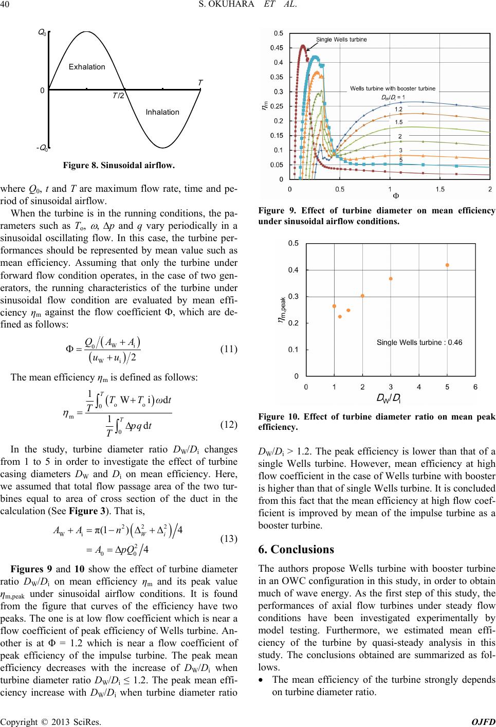
mean efficiency is lower than that of a sin-
REFERENCES
[1] R. Bhattacharick, “Wave Energy
us of Self-Rec-
The mean efficiency at h
proved by means of the impulse turbine as a booster
turbine.
The peak
gle turbine.
yya and M. E. McCorm
Conversion,” Elsevier, Amsterdam, 2003.
[2] T. Setoguchi and M. Takao, “Current Stat
tifying Air Turbines for Wave Energy Conversion,” En-
ergy Conversion and Management, Vol. 47, No. 15-16,
2006, pp. 2382-2396.
doi:10.1016/j.enconman.2005.11.013
[3] S. Raghunathan, “The Wells Air Turbine for Wave En-
ergy Conversion,” Progress in Aerospace Sciences, Vol.
31, No. 4, 1995, pp. 335-386.
doi:10.1016/0376-0421(95)00001-F
[4] M. Takao, T. Setoguchi, Y. Kinoue, K. Kaneko and S.
ormance of
ermine of
Ogata, Y. Tsuritani and Y. Na-
Nagata, “Improvement of Wells Turbine Performance by
Means of End Plate,” Proceedings of the 16th Interna-
tional Offshore and Polar Engineering Conference, San
Francisco, 28 May-2 June 2006, pp. 480-484.
[5] K. Kaneko, T. Setoguchi and M. Inoue, “Perf
Wells Turbine in Oscillating Flow,” Proceedings of the
Current Practices and New Technology in Ocean Engi-
neering, Vol. 2, American Society of Mechanical Engi-
neers (ASME), New York, 1986, pp. 447-452.
[6] T. Setoguchi, K. Kaneko and M. Inoue, “Det
Optimum Geometry of Wells Turbine Rotor for Wave
Power Generator,” Proceedings of 3rd Symposium on
Ocean Wave Utilz, Japan Agency for Marine-Earth Sci-
ence and Technology (JAMSTEC), Tokyo, 1991, pp.
141-149. (in Japanese)
[7] H. Osawa, Y. Washio, T.
gata, “The Offshore Floating Type Wave Power Device
‘Mighty Whale’ Open Sea Tests: Performance of the Pro-
totype,” Proceedings of 12th International Offshore and
Polar Engineering Conference, Kitakyushu, 25-31 May
2002, pp. 595-600.
[8] Wavegen, “Islay LIMPET Project Monitoring Final Re-
port,” 2002. http://www.wavegen.co.uk/pdf/art.1707.pdf
[9] A. Sarmento, A. Brito-Melo and F. Neumann, “Results
from Sea Trials in the OWC European Wave Energy
Plant at Pico, Azores,” 2006.
http://www.pico-owc.net/files/33/cms_b6cda17abb967ed
28ec9610137aa45f7.doc
[10] T. Setoguchi, M. Takao, Y. Kinoue, K. Kaneko, S. San-
thakumar and M. Inoue, “Study on an Impulse Turbine
for Wave Energy Conversion,” International Journal of
Offshore and Polar Engineering, Vol. 10, No. 2, 2000, pp.
145-152.
[11] T. Setoguchi, S. Santhakumar, H. Maeda, M. Takao and
K. Kaneko, “A Review of Impulse Turbine for Wave En-
ergy Conversion,” Renewable Energy, Vol. 23, No. 2,
2001, pp. 261-292. doi:10.1016/S0960-1481(00)00175-0
[12] T. Setoguchi, M. Takao, S. Santhakumar and K. Kaneko,
“Study of an Impulse Turbine for Wave Power Conver-
sion: Effects of Reynolds Number and Hub-to-Tip Ratio
on Performance,” Journal of Offshore Mechanics and
Arctic Engineering, Vol. 126, No. 2, 2004, pp. 137-140.
doi:10.1115/1.1710868
[13] T. Setoguchi, K. Kaneko, H. Maeda, T. W. Kim and M.
Inoue, “Impulse Turbine with Self-Pitch-Controlled Guide
Vanes for Power Conversion: Performance of Mono-
Vane Type,” International Journal of Offshore and Polar
Engineering, Vol. 3, No. 1, 1993, pp. 73-78.
[14] M. Takao, T. Setoguchi, K. Kaneko, T. H. Kim, H.
Maeda and M. Inoue, “Impulse Turbine for Wave Power
Conversion with Air Flow Rectification System,” Inter-
national Journal of Offshore and Polar Engineering, Vol.
12, No. 2, 2002, pp. 142-146.
Nomenclature
a (m2)
steady flow condition (m3/s)
3/s)
f sinusoidal airflow (s)
velocity (m/s)
Greek Letters
across turbine (Pa)
: flow coefficient under steady flow condition
Φ: flow coefficient under sinusoidal flow condition
η: efficiency
ν: hub-to-tip ratio
ρ: density of air (kg/m3)
ω: angular velocity (rad/s)
Subscripts
0: duct
W: Wells turbine
i: impulse turbine
m: mean value
A: flow passage are
CA: input coefficient
CT: torque coefficient
D: casing diameter (m)
l: chord length (m)
q: flow rate under un
Q: flow rate under steady flow condition (m3/s)
Q0: maximum flow rate of sinusoidal airflow (m
r: mean radius (m)
t: time (s)
T: period o
To: torque (N-m)
u: circumferential
v: axial velocity (m/s)
Δp: total pressure drop