Paper Menu >>
Journal Menu >>
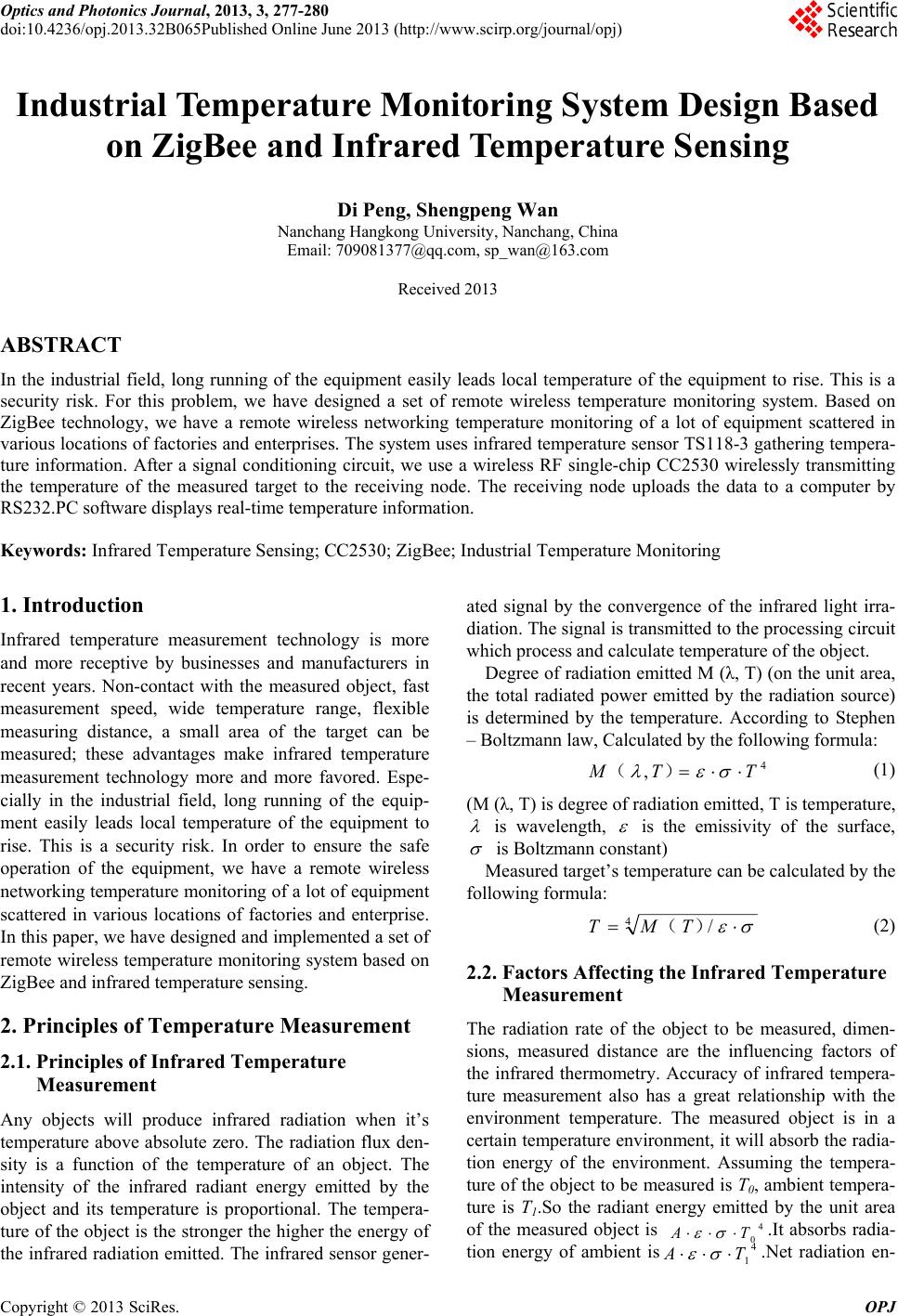 Optics and Photonics Journal, 2013, 3, 277-280 doi:10.4236/opj.2013.32B065Published Online June 2013 (http://www.scirp.org/journal/opj) Industrial Temperature Monitoring System Design Based on ZigBee and Infrared Temperature Sensing Di Peng, Shengpeng Wan Nanchang Hangkong University, Nanchang, China Email: 709081377@qq.com, sp_wan@163.com Received 2013 ABSTRACT In the industrial field, long running of the equipment easily leads local temperature of the equipment to rise. This is a security risk. For this problem, we have designed a set of remote wireless temperature monitoring system. Based on ZigBee technology, we have a remote wireless networking temperature monitoring of a lot of equipment scattered in various locations of factories and enterprises. The system uses infrared temperature sensor TS118-3 gathering tempera- ture information. After a signal conditioning circuit, we use a wireless RF single-chip CC2530 wirelessly transmitting the temperature of the measured target to the receiving node. The receiving node uploads the data to a computer by RS232.PC software displays real-time temperature information. Keywords: Infrared Temperature Sensing; CC2530; ZigBee; Industrial Temperature Monitoring 1. Introduction Infrared temperature measurement technology is more and more receptive by businesses and manufacturers in recent years. Non-contact with the measured object, fast measurement speed, wide temperature range, flexible measuring distance, a small area of the target can be measured; these advantages make infrared temperature measurement technology more and more favored. Espe- cially in the industrial field, long running of the equip- ment easily leads local temperature of the equipment to rise. This is a security risk. In order to ensure the safe operation of the equipment, we have a remote wireless networking temperature monitoring of a lot of equipment scattered in various locations of factories and enterprise. In this paper, we have designed and implemented a set of remote wireless temperature monitoring system based on ZigBee and infrared temperature sensing. 2. Principles of Temperature Measurement 2.1. Principles of Infrared Temperature Measurement Any objects will produce infrared radiation when it’s temperature above absolute zero. The radiation flux den- sity is a function of the temperature of an object. The intensity of the infrared radiant energy emitted by the object and its temperature is proportional. The tempera- ture of the object is the stronger the higher the energy of the infrared radiation emitted. The infrared sensor gener- ated signal by the convergence of the infrared light irra- diation. The signal is transmitted to the processing circuit which process and calculate temperature of the object. Degree of radiation emitted M (λ, T) (on the unit area, the total radiated power emitted by the radiation source) is determined by the temperature. According to Stephen – Boltzmann law, Calculated by the following formula: 4 ,TTM )( (1) (M (λ, T) is degree of radiation emitted, T is temperature, is wavelength, is the emissivity of the surface, is Boltzmann constant) Measured target’s temperature can be calculated by the following formula: 4/ )( TMT (2) 2.2. Factors Affecting the Infrared Temperature Measurement The radiation rate of the object to be measured, dimen- sions, measured distance are the influencing factors of the infrared thermometry. Accuracy of infrared tempera- ture measurement also has a great relationship with the environment temperature. The measured object is in a certain temperature environment, it will absorb the radia- tion energy of the environment. Assuming the tempera- ture of the object to be measured is T0, ambient tempera- ture is T1.So the radiant energy emitted by the unit area of the measured object is .It absorbs radia- tion energy of ambient is.Net radiation en- 4 0 TA 4 1 TA Copyright © 2013 SciRes. OPJ  D. PENG, S. P. WAN 278 ergy emitted per unit area of the object is Q. 4 1 4 0-TATAQ (3) (A is unit area, ε is object emissivity, σ is Stephen - Boltzmann constant) 3. System Hardware Design 3.1. Node Design Temperature monitoring system is designed in this paper. The multiple temperature acquisition nodes are placed in different regions. Measured object’s temperature infor- mation is collected by each node. Temperature data are wirelessly transmitted to a remote receiving node. Be- cause each node is only a short distance transmission, so by the other nodes in multi-hop routing forwarding to reach remote accept node. Remote receiving node even- tually connects to the PC via the serial port. Temperature information is displayed in real-time by the PC software. The node includes the CC2530 module, infrared tem- perature sensor, and a power supply module. The system designs of the node internal block diagram.(Figure 1) CC2530 is a core module. It is a true chip system solu- tions about 2.4 GHz IEEE802.15.4 and ZigBee. It in- cludes a high performance 2.4 GHz DSSS radio trans- ceiver and a high-performance, low-power 8051 micro- controller. It’s suitable for setting up fully functional and inexpensive network nodes. It has a lot of memory, sup- porting for system programming. CC2530 integrate IEEE802.15.4 standard 2.4 GHz band RF transceiver on a single chip, using O-QPSK modulation. It has excellent wireless receiver sensitivity and anti-jamming. It’s the ideal carrier for this paper’s design. 3.2. Temperature Acquisition Circuit The sensor is TS118-3.It’s a non-contact infrared tem- perature sensor. Its function is that the amount of infrared radiation is converted into a voltage signal. (Figure 2) TP- and TP+ output terminal is weak DC voltage sig- nal of measured object’s radiation energy. Ni-RTD is an ambient temperature resistance signal output terminal, and its resistance is K-class. Figure 1. Node internal block diagram. As the ambient temperature signal of infrared sensor output is the value of a resistor, the microcontroller can only processing electrical signals, so before the ambient temperature signal is sent to the MCU processing, signal conversion is necessary. In this design, the resistance signal will be converted to a voltage signal, the principle as shown below. The thermistor with a fixed resistor in series partial pressure, whichever is the voltage on the thermistor input the MCU through an emitter follower, the emitter follower analog signal and digital signal iso- lation to prevent digital signal by the analog signal inter- fere. (Figure 3) Physical layer data format is as follows: As infrared sensor output signal is not only small but also vulnerable to interference, amplifying and filtering circuit must be designed to obtain higher measurement ac- curacy. The measured object temperature signal’s front- end processing module plays a key role in the whole sys- tem. The performance of the module determines the reli- ability and accuracy of the measurement of the entire system. The part of the circuit uses the instrumentation amplifier principle. Add a low-pass filter after amplifica- tion. Butterworth low-pass filter is used in the design of the part. The most important performance indicators of the fil- ter circuit is the pass band cutoff frequency fc = 1/2πRC. Circuit simulation amplitude frequency response as fol- lowing Figure 4 shows. It can be seen from the figure about 200HZ point, attenuation 45dB, basically meet the needs of the design. Figure 2. Infrared temperature sensor. Figure 3. Resistance signal is converted to voltage signal. Copyright © 2013 SciRes. OPJ 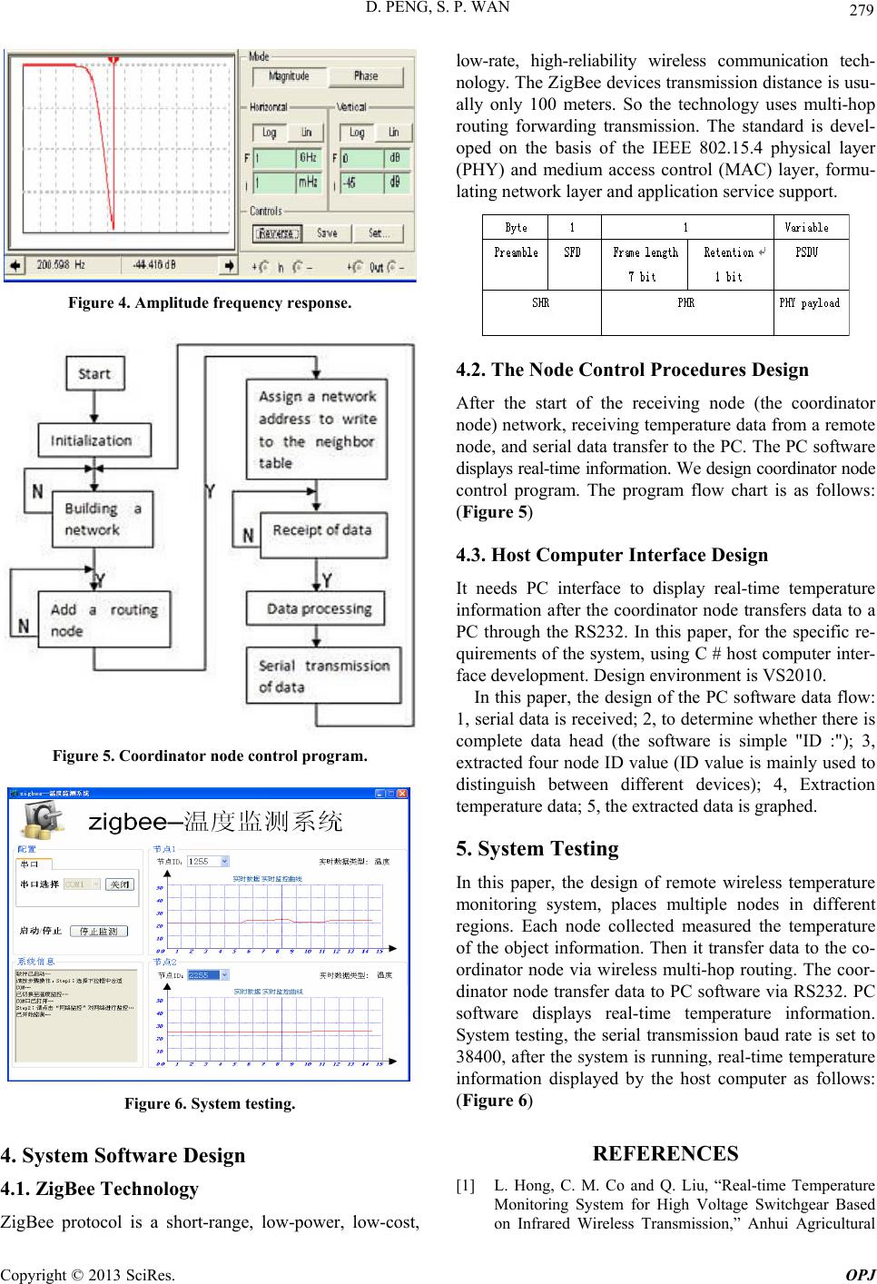 D. PENG, S. P. WAN 279 Figure 4. Amplitude freque ncy response. Figure 5. Coordinator node control progr am. Figure 6. System testing. 4. System Software Design 4.1. ZigBee Technology ZigBee protocol is a short-range, low-power, low-cost, low-rate, high-reliability wireless communication tech- nology. The ZigBee devices transmission distance is usu- ally only 100 meters. So the technology uses multi-hop routing forwarding transmission. The standard is devel- oped on the basis of the IEEE 802.15.4 physical layer (PHY) and medium access control (MAC) layer, formu- lating network layer and application service support. 4.2. The Node Control Procedures Design After the start of the receiving node (the coordinator node) network, receiving temperature data from a remote node, and serial data transfer to the PC. The PC software displays real-time information. We design coordinator node control program. The program flow chart is as follows: (Figure 5) 4.3. Host Computer Interface Design It needs PC interface to display real-time temperature information after the coordinator node transfers data to a PC through the RS232. In this paper, for the specific re- quirements of the system, using C # host computer inter- face development. Design environment is VS2010. In this paper, the design of the PC software data flow: 1, serial data is received; 2, to determine whether there is complete data head (the software is simple "ID :"); 3, extracted four node ID value (ID value is mainly used to distinguish between different devices); 4, Extraction temperature data; 5, the extracted data is graphed. 5. System Testing In this paper, the design of remote wireless temperature monitoring system, places multiple nodes in different regions. Each node collected measured the temperature of the object information. Then it transfer data to the co- ordinator node via wireless multi-hop routing. The coor- dinator node transfer data to PC software via RS232. PC software displays real-time temperature information. System testing, the serial transmission baud rate is set to 38400, after the system is running, real-time temperature information displayed by the host computer as follows: (Figure 6) REFERENCES [1] L. Hong, C. M. Co and Q. Liu, “Real-time Temperature Monitoring System for High Voltage Switchgear Based on Infrared Wireless Transmission,” Anhui Agricultural Copyright © 2013 SciRes. OPJ  D. PENG, S. P. WAN Copyright © 2013 SciRes. OPJ 280 University. IEEE, 2010. [2] Model TS118-3 Thermopile Sensor. Measurement spe- cialties, June 2008. [3] A. Livshitz, B. Bukengolts, B. H. Chudnovsky and B. A. Chudnovsky, “On-Line Temperature Monitoring Of Power Distribution Equipment,” Material IEEE, 2005 [4] F.Y. Ren, H. N. Huang and C. Lin, “Wireless Sensor Networks,” Journal of Software, Vol.14, No.7, 2003, pp. 1282-1291. [5] P. Kinney. “ZigBee Technology: Wireless Control that Simply Works,” Communication Design Conference, 2003. [6] Texas Instrument.CC2530 User’s Guide. Dallas: Texas Instrument Corporation, 2009. [7] Texas Instrument. CC2530-Software Examples. Dallas: Texas Instrument Corporation, 2009. |