Open Journal of Fluid Dynamics, 2013, 3, 1-8
http://dx.doi.org/10.4236/ojfd.2013.32A001 Published Online July 2013 (http://www.scirp.org/journal/ojfd)
Design of Half-Ducted Axial Flow Fan Considering
Radial Inflow and Outflow
—Comparison of Half-Ducted Design with Ducted Design
Pin Liu1, Yusuke Oka1, Yoichi Kinoue1*, Norimasa Shiomi1, Toshiaki Setoguchi1, Yingzi Jin2
1Department of Mechanical Engineering, Saga University, Saga, Japan
2Faculty of Mechanical Engineering & Automation, Zhejiang Sci-Tech University, Hangzhou, China
Email: *kinoue@me.saga-u.ac.jp
Received May 27, 2013; revised June 4, 2013; accepted June 11, 2013
Copyright © 2013 Pin Liu et al. This is an open access article distributed under the Creative Commons Attribution License, which
permits unrestricted use, distribution, and reproduction in any medium, provided the original work is properly cited.
ABSTRACT
Half-ducted fan and ducted fan have been designed and numerically analyzed for investigating the radial flow effect on
the overall performance and the three dimensional flow field in design. Based on quasi-three dimensional flow theory,
the meridional flow was calculated by adopting the radial balance equations, while the calculation of the blade to blade
flow was obtained by 2D cascade data with the correction by a potential flow theory. Two types of axial flow fan were
designed. One is the full ducted case as if it was in the straight pipe and another is the half-ducted case with the radial
inflow and outflow. The previous experimental results of authors were used to decide the inclinations of both the inflow
and outflow. And the circular arc blade with equal thickness was adopted. The numerical results indicate that both of
the designed fans can reach the specified efficiency and also the efficiency surpasses more than 11%. Furthermore, the
static pressure characteristic of half-ducted fan is much better than that of ducted fan. In comparison of the three di-
mensional internal flow of these two fans, the improvement of the flow angle at inlet and outlet, the distributions of
velocity in the flow field and the pressure distributions on the blade surfaces can be achieved more successfully in ac-
cordance with the design intension on consideration of flow angle in design. The conclusion that half-ducted design
with considering radial inflow and outflow is feasible and valid in comparison with ducted design for axial flow fans
has been obtained at the end of the paper.
Keywords: Axial Flow Fan; Rotational Vortex; Half-Ducted Fans; Internal Flow; Numerical Analysis
1. Introduction
A lot of axial fans, which are small size and low pressure
rise, are used in our daily life. Some common examples
are a room ventilation fan, a radiator fan in car engine
room, a power unit cooling fan of personal computer, and
so on. Many of them are designed by the inverse design
method. The inverse methods make a close link between
the intention of designer and the blade geometry. Zan-
geneh [1] introduced an inverse method of a fully 3D
compressible flow for the design of radial and mixed
flow turbomachinery blades. The blade shape of an initial
guess is obtained by the specified rVt and assuming uni-
form velocity. The 3D inverse design method was also
applied to design vaned diffusers in centrifugal com-
pressor and centrifugal and mixed flow impellers in order
to investigate highly nonuniform exit flow and analyze
and minimize the generation of the secondary flows re-
spectively [2,3]. The theory and application of a novel
3D inverse method for the design of turbomachinery
blade in rotating viscous flow were systematically re-
ported [4].
The inverse methods of axial flow fans can be divided
into the free vortex design and controlled vortex design.
In the controlled vortex design, the axial velocity can be
nonuniform and the designed blade circulation can be
able to specified nonconstant. Most of the axial flow fans
are designed by the controlled vortex design. The proper
blade loading distributions and reduced loss near the tip
can be reached by the controlled vortex design [5]. The
controlled vortex design also provides a method for the
multistage machinery with a reasonable distribution of
exit flow angle [6]. However, all these studies are not
taking the radial velocity component into account. It is
advantageous to consider the radial velocity in nonfree
*Corresponding author.
C
opyright © 2013 SciRes. OJFD
P. LIU ET AL.
2
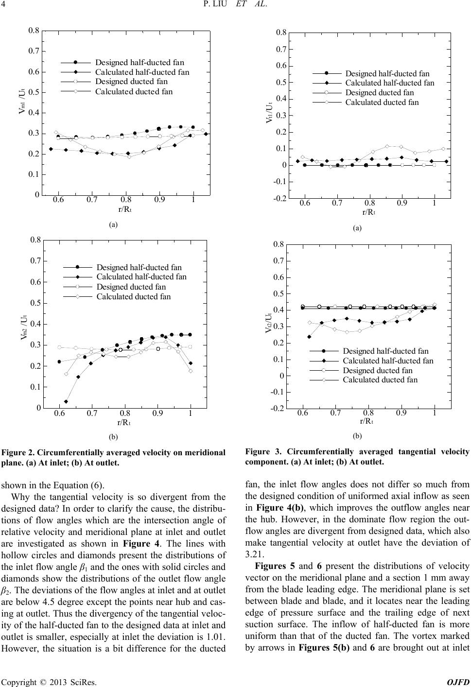
vortex design, which was investigated by three dimen-
sional laser Doppler anemometer measurement [7].
In this paper, the radial flows at both the inflow and
the outflow have been considered for the improvement of
the design method. Two types of axial flow fans are de-
signed by the controlled vortex design by specifying the
constant tangential velocity both at inlet and outlet of the
rotor. One type is ducted axial flow fan which is usually
designed to prescribe almost uniform inflow and outflow
as if it was in the straight pipe. However, many axial
flow fans are not used in the straight pipe, such as the
application of using in the ventilation and cooling sys-
tems without pipe. Thus it is important to take the real
flow situation into account in design. Then the other type
which is half-ducted axial flow fan was designed to com-
pare with the traditional design of ducted ones by speci-
fying the flow angles according to the previous experi-
mental results of authors [8,9].
2. Design and Numerical Method
The quasi three-dimensional flow theory was applied to
investigate the flow of the axial flow fans. The merid-
ional flow and the revolutional flow between blades were
calculated by the method of streamline curvature. Based
on the theory, the meridional flow was calculated by
adopting the radial balance equations [10], while the
calculation of the blade to blade flow was obtained by
2D cascade data with the correction by a potential flow
theory so as to consider the axial flow velocity change
and the inclination of the flow surface [11].
In calculation of meridional flow, the following force
balance equation was evaluated at the quasi-orthogonal
direction on meridional plane:
 
2
2
d
d
m
m
V
A
qV Bq
q (1)
when the compressibility of the fluid is ignored,

1sinsind
2t
cos d
m
Aq rrq

an

 


(2)


d
d
1
2dd
t
tt
rV
PV
Bq qr q

 


(3)


 

2
expd expd
m
i
V
A
qqBqAqq C



 
(4)
The arbitrary constant Ci can be got by the relative
equation of mass flow rate and velocity. The energy per
second getting through outlet of the rotor can be calcu-
lated by the following equation on assumption of con-
stant Vt at inlet and outlet (0 at inlet):
222
cos d
c
h
q
th mt
Bq
m
EI rVuV
K

 
 22
q
2t
(5)
So that Vt2 can be got. The total pressure rise is pre-
sumed to be able to calculate by the Euler equation as:
2t
PP uV
  (6)
Therefore, the meridional velocity and the tangential
velocity can be obtained so that the calculation of merid-
ional flow is finished.
The blade profile on the revolutional plane was se-
lected by referring to the diagram of circular arc carpet.
Thus, the circular arc blade with equal thickness and
quadrilateral blade on the meridional plane was adopted.
Two types of axial flow fan were designed in this pa-
per. One is the ducted case as if it was in the straight pipe
and another is the half-ducted case with the radial inflow
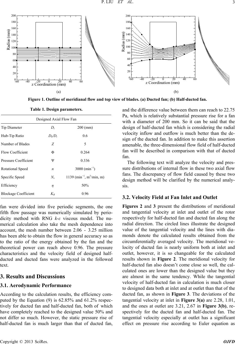
and outflow. The blade shapes on top view were obtained
showing in Figure 1 on right side. The highly twisted
blades can be avoided by half ducted fan with the con-
trolled vortex design by specifying the flow angles. For
the ducted fan, the streamlines on the meridional plane
are uniform and parallel to each other, as shown in Fig-
ure 1(a). While the streamlines of half-ducted fan shown
in Figure 1(b) obviously differ from that of ducted fan
because the inclinations of inflow and outflow are given
based on the experimental data [8,9] so as to consider the
effect of radial velocity component on the internal flow
field. The flow angles of the streamlines are given 63, 16,
38 degrees respectively on tip streamline at inlet, on tip
streamline at outlet, on hub streamline at outlet.
Table 1 shows the designed parameters of ducted fan
and half-ducted fan. All these parameters are specified
the same value for both of the designed fans. Besides, the
blade shape near the hub and the casing is not straight
line but modified into spline curve, which can be seen in
Figure 7(a). The flow rate and pressure rise are repre-
sented with nondimensional form of flow coefficient and
pressure rise coefficient which are defined as:

22
4
πth
Q
DDU

t
(7)
2
2
s
t
p
U
(8)
and
s
pQ
T
(9)
The designed fan blade profile data were tackled in the
commercial software for the analysis of three-dimen-
sional flow. In order to increase the speed of the numeri-
cal simulation, the internal flw fields of the axial flow o
Copyright © 2013 SciRes. OJFD
P. LIU ET AL.
Copyright © 2013 SciRes. OJFD
3
Radius (mm)
z Coordination (mm)
-60-40-20020 40 60
0
20
40
60
80
100
120
140
160
180
200
z Coordination (mm)
Radius (mm)
-60 -40 -200204060
0
20
40
60
80
100
120
140
160
180
200
(a) (b)
Figure 1. Outline of meridianal flow and top view of blades. (a) Ducted fan; (b) Half-ducted fan.
Table 1. Design parameters. and the difference value between them can reach to 22.75
Pa, which is relatively substantial pressure rise for a fan
with a diameter of 200 mm. So it can be said that the
design of half-ducted fan which is considering the radial
velocity inflow and outflow is much better than the de-
sign of the ducted fan. In addition to make this assertion
amenable, the three-dimensional flow field of half-ducted
fan will be described in comparison with that of ducted
fan.
Designed Axial Flow Fan
Tip Diameter Dt 200 (mm)
Hub-Tip Ratio Dh/Dt 0.6
Number of Blades Z 5
Flow Coefficient Φ 0.264
Pressure Coefficient Ψ 0.336
Rotational Speed n 3000 (min1)
Specific Speed Ns 1139 (min1, m3/min, m)
Efficiency η 50%
Blockage Coefficient KB 0.96
The following text will analyze the velocity and pres-
sure distributions of internal flow in these two axial flow
fans. The discrepancy of flow field caused by these two
design method will be clarified by the numerical analy-
sis.
3.2. Velocity Field at Fan Inlet and Outlet
Figures 2 and 3 present the distributions of meridional
and tangential velocity at inlet and outlet of the rotor
respectively for half-ducted fan and ducted fan along the
radial direction. The circled lines illustrate the designed
value of the tangential velocity and the lines with dia-
monds denote the calculated results obtained from the
circumferentially averaged velocity. The meridional ve-
locity of ducted fan is nearly uniform both at inlet and
outlet, however, it is so changeable for the calculated
results shown in Figure 2. The meridional velocity for
half-ducted fan also doesn’t come close so well, the cal-
culated ones are lower than the designed value but they
are almost in the same tendency. While the tangential
velocity of half-ducted fan in calculation is much closer
to designed data both at inlet and at outlet than that of the
ducted fan, as shown in Figure 3. The deviations of the
tangential velocity at inlet in Figure 3(a) are 2.28, 1.01,
and the ones at outlet are 3.21, 2.67 in Figure 3(b), re-
spectively for the ducted fan and half-ducted fan. The
tangential velocity especially at outlet has a significant
effect on pressure rise according to Euler equation as
fan were divided into five periodic segments, the one
fifth flow passage was numerically simulated by perio-
dicity method with RNG k-ε viscous model. The nu-
merical calculation also take the mesh dependence into
account, the mesh number between 2.06 - 3.25 million
has been able to obtain the flow in general accuracy so as
to the ratio of the energy obtained by the fan and the
theoretical power can reach above 0.96. The pressure
characteristics and the velocity field of designed half-
ducted and ducted fans were analyzed in the followed
text.
3. Results and Discussions
3.1. Aerodynamic Performance
According to the calculation results, the efficiency com-
puted by the Equation (9) is 62.85% and 61.2% respec-
tively for ducted fan and half-ducted fan, both of which
have completely reached to the designed value 50% and
not differ so much. However, the static pressure rise of
half-ducted fan is much larger than that of ducted fan,
P. LIU ET AL.
4
V /U
r/R
Designed half-ducted fan
Calculated half-ducted fan
Designed ducted fan
Calculated ducted fan
m1 t
t
0.6 0.70.8 0.91
0
0.1
0.2
0.3
0.4
0.5
0.6
0.7
0.8
(a)
V /U
r/R
Designed half-ducted fan
Calculated half-ducted fan
Designed ducted fan
Calculated ducted fan
t
m2 t
0.6 0.70.8 0.91
0
0.1
0.2
0.3
0.4
0.5
0.6
0.7
0.8
(b)
Figure 2. Circumferentially averaged velocity on meridional
plane. (a) At inlet; (b) At outlet.
shown in the Equation (6).
Why the tangential velocity is so divergent from the
designed data? In order to clarify the cause, the distribu-
tions of flow angles which are the intersection angle of
relative velocity and meridional plane at inlet and outlet
are investigated as shown in Figure 4. The lines with
hollow circles and diamonds present the distributions of
the inlet flow angle β1 and the ones with solid circles and
diamonds show the distributions of the outlet flow angle
β2. The deviations of the flow angles at inlet and at outlet
are below 4.5 degree except the points near hub and cas-
ing at outlet. Thus the divergency of the tangential veloc-
ity of the half-ducted fan to the designed data at inlet and
outlet is smaller, especially at inlet the deviation is 1.01.
However, the situation is a bit difference for the ducted
V /U
r/R
Designed half-ducted fan
Calculated half-ducted fan
Designed ducted fan
Calculated ducted fan
t
t1 t
0.60.70.80.9 1
-0.2
-0.1
0
0.1
0.2
0.3
0.4
0.5
0.6
0.7
0.8
(a)
r/R
V /U
Designed half-ducted fan
Calculated half-ducted fan
Designed ducted fan
Calculated ducted fan
t
t2 t
0.6 0.7 0.8 0.91
-0.2
-0.1
0
0.1
0.2
0.3
0.4
0.5
0.6
0.7
0.8
(b)
Figure 3. Circumferentially averaged tangential velocity
component. (a) At inlet; (b) At outlet.
fan, the inlet flow angles does not differ so much from
the designed condition of uniformed axial inflow as seen
in Figure 4(b), which improves the outflow angles near
the hub. However, in the dominate flow region the out-
flow angles are divergent from designed data, which also
make tangential velocity at outlet have the deviation of
3.21.
Figures 5 and 6 present the distributions of velocity
vector on the meridional plane and a section 1 mm away
from the blade leading edge. The meridional plane is set
between blade and blade, and it locates near the leading
edge of pressure surface and the trailing edge of next
suction surface. The inflow of half-ducted fan is more
uniform than that of the ducted fan. The vortex marked
by arrows in Figures 5(b) and 6 are brought out at inlet
Copyright © 2013 SciRes. OJFD
P. LIU ET AL.
Copyright © 2013 SciRes. OJFD
5
CFD-
Designed-
CFD-
Designed-
(degree)
r/R
t
Half-ducted fan




0.6 0.7 0.80.91
0
10
20
30
40
50
60
70
80
90
CFD-
Designed -
CFD-
Designed -
(degree)
r/R
t
Half-ducted fan




0.6 0.70.8 0.91
0
10
20
30
40
50
60
70
80
90
(a) (b)
Figure 4. DisDucted fan.
tributions of flow angles. (a) Half-ducted fan; (b)
(a)
(b)
Figure 5. Distributions of velocity vector on meridional plane. (a) Half-ducted fan; (b) Ducted fan.
P. LIU ET AL.
6
Figure 6. Distributions of velocity vector on inlet section plane (ducted fan).
f ducted fan, which cause the meridional velocity to de-
3.3. Pressure Distributions
butions of static pressure
gure 9 presents circumferentially averaged total
pr
even they are designed by specifying the same flow pa-
usions
ed fan have been designed and
stigating the radial flow
ed fan gets designed with one in the synchro-
no
dominate flow region by considering of
flo
edge to trailing
ed
at inlet and
ou
o
crease as shown in Figure 2(a) and the tangential veloc-
ity to increase as shown in Figure 3(a).
Figures 7 and 8 show the distri
on the suction surface and the pressure surface respec-
tively. The static pressure on suction surface is negative
pressure and increases from the leading edge to the trail-
ing edge. However, the static pressure on suction surface
of ducted fan increases from the mid part to the leading
edge and suddenly forms a high pressure center near the
tip as shown in Figure 7(b). Furthermore, the static pres-
sure on pressure surface of ducted fan in Figure 8(b)
decreases to negative near the leading edge. These phe-
nomena observed in ducted fan weaken the suction per-
formance of suction surface and make the flow twist at
inlet region as seen in Figures 5(b) and 6. While the
performance of half-ducted fan is better than that of
ducted fan and the static pressure uniformly increases on
pressure surface with respect to the increment of radius
which follows the assumption in design well in Equation
(6).
Fi
essure of half-ducted fan and ducted fan at outlet along
radial direction. The total pressure of half-ducted fan is
larger than that of ducted fan except in the casing areas
and near the hub region. Furthermore, the meridional
velocity dominating the flow field at outlet makes the
mid-span region the most important part of the flow as
seen in Figure 2(b), which is beneficial to the energy
acquisition. Therefore, the static pressure rise of half-
ducted fan would be able to surpass that of ducted fan
rameters.
4. Concl
Half-ducted fan and duct
numerically analyzed for inve
effect on the overall performance and the three dimen-
sional flow field in design. Higher twisted blade can be
avoided by the design of half ducted fan. The numerical
results indicate that both of the designed fans can reach
the specified efficiency and also surpass more than 11%.
Furthermore, the static pressure rise of half-ducted fan is
16.6% more than that of ducted fan. In comparison of the
three dimensional internal flow of these two fans, a cer-
tain number of interesting features can be summarized as
follows:
1) Compared with ducted fan, the meridional velocity
of half-duct
us tendency, and the tangential velocity is much closer
to designed data, which has a significant effect on the
pressure rise.
2) The distributions of flow angle and velocity are im-
proved in the
w angle in design of half-ducted fan.
3) The static pressure gradually increases on suction
surface of half-ducted fan from leading
ge, and also uniformly increases on pressure surface
with the increment of radius in accordance with the de-
sign assumption. While in the case of ducted fan, the
pressure distributions on the suction and pressure sur-
faces are not beneficial for the pressure rise.
As mentioned above, on consideration of flow angle in
design, the improvement of the flow angle
tlet, the distributions of velocity in the flow field and
Copyright © 2013 SciRes. OJFD
P. LIU ET AL. 7
-500-450-400-350-300-250-200-150-100-50050100
0
-50
-100
-250
-250
-300
-400
SS
LE TE
-250
-200
0
100 -200
-150 -500
-300
LE TE
SS
(a) (b)
Figure 7. Distributions fan; (b) Ducted fan
. of static pressure on suction surface. (a) Half-ducted
-100-500245079100 150 200 250 300 350 400
0
50
100
PS
LE TE
50
24
0
-50
-100
LE TE
PS
(a) (b)
Figure 8. Distributions oted fan; (b) Ducted fan.
f static pressure on pressure surface. (a) Half-duc
P
t2
r/R
t
Half-ducted fan
Ducted fan
(Pa)
0.60.7 0.80.91
20
40
60
80
100
120
140
160
180
200
Figure 9. Total pressure at outlet.
ureces can be
wledgements
owledge the research fund
2013 from the Sasagawa Scientific Research foundation.
in Fluids, Vol.-624.
the press
a
distributions on the blade surfa
chieved more successfully. Therefore, half-ducted de-
sign with considering radial inflow and outflow is feasi-
ble and valid in comparison with ducted design for axial
flow fans.
5. Ackno
The authors gratefully ackn
REFERENCES
[1] M. Zangeneh, “A Compressible Three-Dimensional De-
sign Methhod for Radial and Mixed Flow Turbomachin-
ery Blades,” InNumerical Methods ternational Journal of
13, No. 5, 1991, pp. 599
doi:10.1002/fld.1650130505
[2] M. Zangeneh, “Inverse Design of Centrifugal Compressor
Vaned Diffusers in Inlet Shear Flows,” ASME Transac-
tions on Journal of Turbomachinery, Vol. 1
1996, pp. 385-393.
18, No. 2,
5/1.2836653doi:10.111
. 4, 1998, pp.
[3] M. Zangeneh, A. Goto and H. Harada, “On the Design
Criteria for Suppression of Secondary Flows in Centrifu-
gal and Mixed Flow Impellers,” ASME Transactions on
Journal of Turbomachinery, Vol. 120, No
723-735. doi:10.1115/1.2841783
[4] W. T. Tiow and M. Zangeneh, “A Novel 3D Inverse
Method for the Design of Turbomachinery Blades in Ro-
tational Viscous Flow: Theory and Applications,” Task
Quarterly, Vol. 6, No. 1, 2002, pp. 63-78.
of Power and
[5] J. Vad, A. R. A. Kwedikha, et al., “Aerodynamic Effects
of Forward Blade Skew in Axial Flow Rotors of Con-
trolled Vortex Design,” Proceedings of the Institution of
Mechanical Engineers, Part A: Journal
Energy, Vol. 221, No. 7, 2007, pp. 1011-1023.
doi:10.1243/09576509JPE420
[6] S. J. Gallimore, J. J. Bolger, et al., “The Use of Sweep
and Dihedral in Multistage Axial Flow Compressor Blad-
ing—Parts 1 and 2,” ASME Transactions on Journal of
Copyright © 2013 SciRes. OJFD
P. LIU ET AL.
8
Turbomachinery, Vol. 124, No. 4, 2002, pp. 521-541.
doi:10.1115/1.1507333
[7] J. Vad and F. Bencze, “Three-Dimensional Flow in Axial
Flow Fans of NonFree Vortex Design,” International
Journal of Heat and Fluid Flow, Vol. 19, No. 6, 1998, p
601-607.
p.
doi:10.1016/S0142-727X(98)10004-8
Flow Problems,” ASME Transactions on
[8] N. Shiomi, Y. Kinoue and T. Setoguchi, “Experimental
Study on Flow Fields with Vortex in a Semi-Opened
Propeller Fan,” Turbomachinery, Vol. 40, No. 11, 2012,
pp. 688-696.
[9] N. Shiomi, Y. Kinoue and T. Setoguchi, “Three Dimen-
sional Velocity Fields at Rotor Outlet of a Semi-Opened
Propeller Fan,” Turbomachinery, Vol. 40, No. 4, 2012, pp.
218-225.
[10] R. A. Novak, “Streamline Curvature Computing Proce-
dures for Fluid-
Journal of Engineering for Power, Vol. 89, No. 2, 1967,
pp. 478-490. doi:10.1115/1.3616716
[11] M. Inoue, T. Ikui, Y. Kmada and M. Tashiro, “A Quasi
Three-Dimensional Design of Diagonal Flow Impellers
omenclature
y
halpy
e
locity
d (m/s)
le
ε: angle between q line and normal of meridional stream-
line
ospheric density
icient
lution plane
fficient
ane
tip
by Use of Cascade Data,” Proceeding of 10th Symposium
of IAHR, Tokyo, 28 September-2 October1980, pp. 403-
414.
N
D: diameter (m)
E2: theoretical energ
Ith: theoretical ent
Ps: static pressure (Pa)
Pt: total pressure (Pa)
Q: flow rate (m³/s)
q: quasi-orthogonal lin
Rt: blade radius (m)
r: radial distance (m)
T: torque (N·m)
U2: circumferential ve
Ut: blade tip spee
Vm: meridional velocity
Vt: tangential velocity
Greek Letters
β: relative flow ang
η: efficiency
ρ: atm
τ: torque coeff
Φ: flow coefficient
φ: slope angle of revo
Ψ: pressure-rise coe
ω: rotating speed
Subscripts
h: hub
m: meridional pl
t: blade
1/2: inlet/outlet
Copyright © 2013 SciRes. OJFD