X. ZHANG ET AL. 163
on the adjustable system parameters including the delay
time of the feedback light τ, and the bias injection current
I of the SRL, the feedback coefficient Kf. In this paper, τ
is set to 179 fs, which means that the feedback waveguide
is about 15μm longer than that of the corresponding part
of the resonant cavity of the SRL. We focus on the effect
of the feedback coefficient and the bias injection current
of the SRL on the nonlinear system.
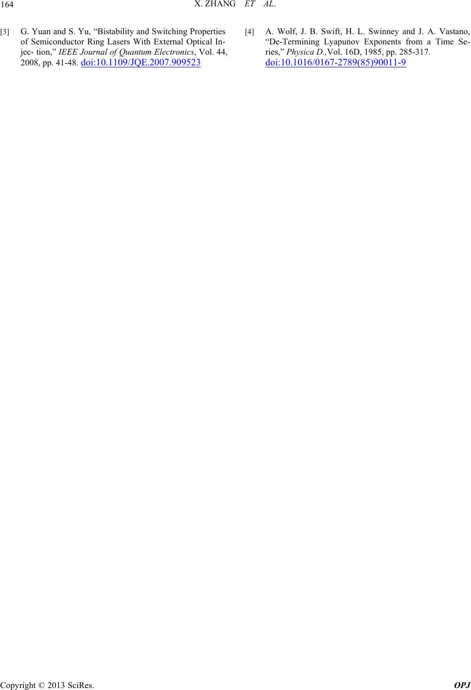
It is well known that any system containing at least
one positive lyapunov exponent is defined to be chaotic
and the larger the magnitude of the positive lyapunov
exponent is, the more chaotic the system is. The map of
largest lyapunov exponent of the system is presented in
Figure 2 as a function of the feedback coefficient and the
bias injection current of the SRL, which is approximately
computed based on the classic Wolf’s algorithm [4]. It is
clear that the system is chaotic for the most part of the
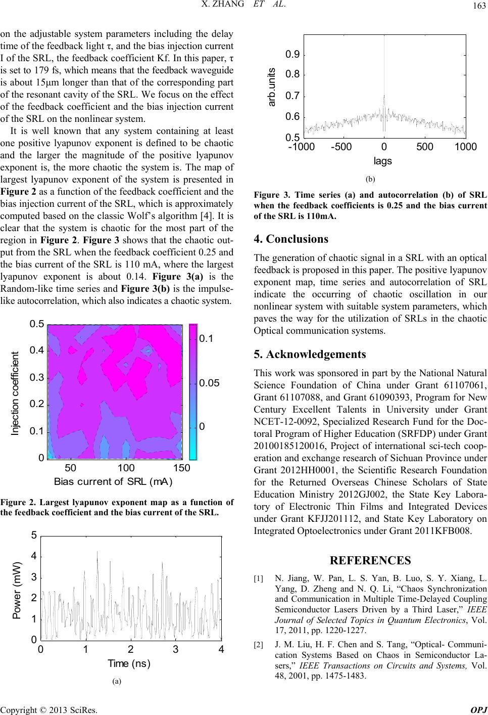
region in Figure 2. Figure 3 shows that the chaotic out-
put from the SRL when the feedback coefficient 0.25 and
the bias current of the SRL is 110 mA, where the largest
lyapunov exponent is about 0.14. Figure 3(a) is the
Random-like time series and Figure 3(b) is the impulse-
like autocorrelation, which also indicates a chaotic system.
Injection coefficient
Bias current of SRL (mA)
50 100 150
0
0.1
0.2
0.3
0.4
0.5
0
0.05
0.1
Figure 2. Largest lyapunov exponent map as a function of
the feedback coefficient and the bias current of the SRL.
01234
0
1
2
3
4
5
Time (ns)
Power (mW)
(a)
-1000 -5000500 1000
0.5
0.6
0.7
0.8
0.9
lags
arb.units
(b)
Figure 3. Time series (a) and autocorrelation (b) of SRL
when the feedback coefficients is 0.25 and the bias current
of the SRL is 110mA.
4. Conclusions
The generation of chaotic signal in a SRL with an optical
feedback is proposed in this paper. The positive lyapunov
exponent map, time series and autocorrelation of SRL
indicate the occurring of chaotic oscillation in our
nonlinear system with suitable system parameters, which
paves the way for the utilization of SRLs in the chaotic
Optical communication systems.
5. Acknowledgements
This work was sponsored in part by the National Natural
Science Foundation of China under Grant 61107061,
Grant 61107088, and Grant 61090393, Program for New
Century Excellent Talents in University under Grant
NCET-12-0092, Specialized Research Fund for the Doc-
toral Program of Higher Education (SRFDP) under Grant
20100185120016, Project of international sci-tech coop-
eration and exchange research of Sichuan Province under
Grant 2012HH0001, the Scientific Research Foundation
for the Returned Overseas Chinese Scholars of State
Education Ministry 2012GJ002, the State Key Labora-
tory of Electronic Thin Films and Integrated Devices
under Grant KFJJ201112, and State Key Laboratory on
Integrated Optoelectronics under Grant 2011KFB008.
REFERENCES
[1] N. Jiang, W. Pan, L. S. Yan, B. Luo, S. Y. Xiang, L.
Yang, D. Zheng and N. Q. Li, “Chaos Synchronization
and Communication in Multiple Time-Delayed Coupling
Semiconductor Lasers Driven by a Third Laser,” IEEE
Journal of Selected Topics in Quantum Electronics, Vol.
17, 2011, pp. 1220-1227.
[2] J. M. Liu, H. F. Chen and S. Tang, “Optical- Communi-
cation Systems Based on Chaos in Semiconductor La-
sers,” IEEE Transactions on Circuits and Systems, Vol.
48, 2001, pp. 1475-1483.
Copyright © 2013 SciRes. OPJ