Optics and Photonics Journal, 2013, 3, 139-142
doi:10.4236/opj.2013.32B034 Published Online June 2013 (http://www.scirp.org/journal/opj)
LED Modulation Characteristics in a Visible-Light
Communication System*
Yanrong Pei, Shaoxin Zhu, Hua Yang, Lixia Zhao, Xiaoyan Yi, Junxi Wang, Jinmin Li
Institute of Semiconductors, Chinese Academy of Sciences, Beijing, China
Email: yrpei@semi.ac.cn
Received 2013
ABSTRACT
This paper conducts a research on modulation characteristics of blue light-emitting diodes (LEDs) used in a visible-light
communication (VLC) system. Through analysis of the modulation characteristics of LEDs with different emitting sizes,
we find that there is a similar linear relationship between LED’s 3dB bandwidth and the operation current density. This
experiment also shows that high series resistance is one major issue that limits our LED's modulation speed. To further
improve the LED bandwidth, the resistance can be reduced by optimizing device layout as well as reducing material
bulk resistance. Clearly, this study provides an approach to increase the modulation bandwidth of GaN-based LEDs for
VLC systems.
Keywords: LED; Visible-light Communication (VLC); Modulation Characteristics; 3dB Bandwidth; Current Density
1. Introduction
With the rapid development of modern solid-state light-
ing, light-emitting diodes (LEDs) are increasingly used
in a wide range of display, signaling and illumination
applications [1]. Because of the long lifetime and high
energy efficiency, LED is becoming one of the dominant
illumination technologies [1,2]. In addition, these
small-sized and energy-efficient devices tend to be used
in both illumination and communication: visible-light
communication (VLC) is attracting a lot of research in-
terests in Asia, Europe and the U.S. [1,3]. Using GaN-
based LEDs as the signal sources in VLC systems, the
modulated signal is able to transmit digital data beyond
the perception speed of human eyes [4]. Therefore, the
double functions of LEDs make them popular in recent
researches on the area of free space VLC system.
A nonreturn-to-zero (NRZ) system using a postequal-
ized white LED at 100 Mb/s has been reported in [1], and
a discrete multi-tones (DMT) modulation of white LED
has reached a data rate of 513 Mbit/s in [5]. Furthermore,
a single RGB LED luminary with the DMT modulation
has achieved a rate of 813 Mbit/s in [6]. A research of
white LED modulation bandwidth and modulation char-
acteristics has been reported in [4]. And also the LED
spatial light intensity effect on the amplitude-frequency
characteristics of VLC has been reported in [7]. Re-
sponse frequency of LED is directly affecting the avail-
able bandwidth of VLC system [4]. Wherefore, increas-
ing the frequency response of LED is the primary event
to achieve high speed VLC, when chasing high-power
LED simultaneously [4]. In this paper, we demonstrate
that the current density on LED affects the response fre-
quency of LED, which determines the modulation band-
width of LED.
2. Experimental Setup
As Figure 1 inset shows that the wavelength of LED in
this experiment is approximately 450 nm, which is the
common wavelength of blue LEDs. This curve is meas-
ured with the integrating sphere using 45 * 45 mil blue
LED.
Figure1. The P-I curve of LED modulation. Inset: The spectra
of the light sources in this experiment.
*This work supported by the National High Technology Research and
Development Program of China (863 Program), No. 2011AA03A105.
Copyright © 2013 SciRes. OPJ
Y. R. PEI ET AL.
140
A typical LED’s current-voltage (I-V) curve is clearly
known. The LED is single conduction and when the bias
voltage exceeds a certain turn-on value VA, the LED can
operate in the linear region (work area). The turn-on
voltage of the LED in this study is about 2.8 V. There-
fore, in order to ensure the LED work in the linear region,
the bias voltage should be higher than 3 V. The modula-
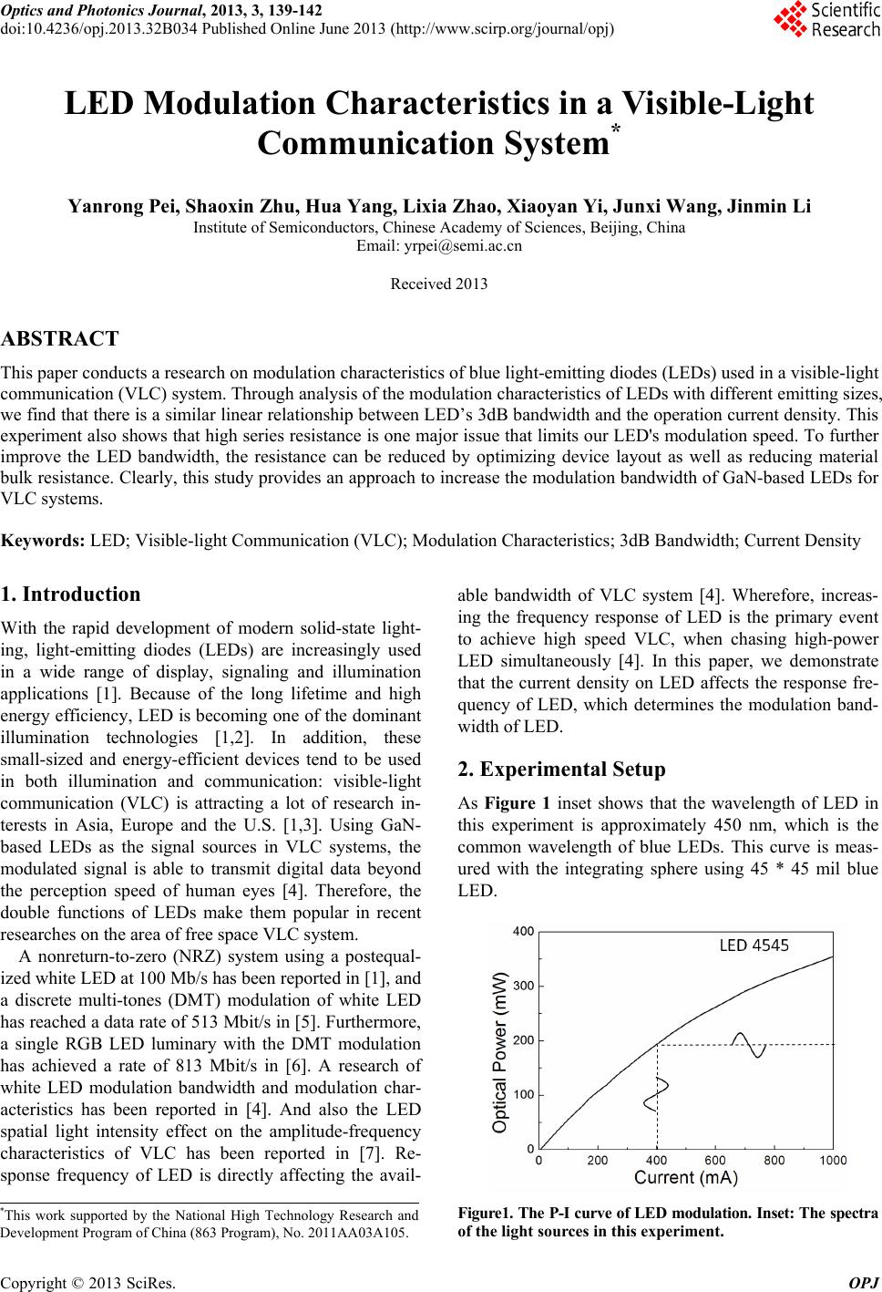
tion capability of a LED is described with optical power
and electrical current (P-I curve). In Figure1, the P-I
curve was approximately linear without a threshold cur-
rent, so the LED’s optical power output can be linearly
modulated with a small input voltage signal that is biased
above VA.
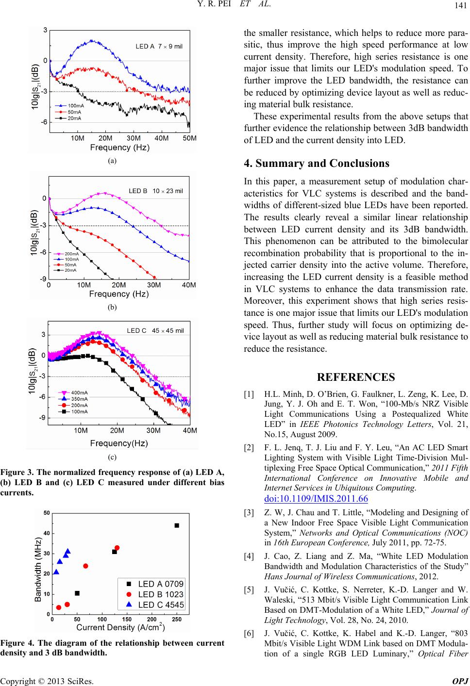
The bandwidth measurement setup for the VLC sys-
tem is shown in Figure 2 and the parameters of each
component were listed in Table 1. The VLC transmitter
consists of an amplifier a power supply and a bias-T. The
receiver comprises a photo-detector that was Positive-
Intrinsic Negative diode (PIN diode) or Avalanche Photo
Diode (APD). LED that was the light source in transmit-
ter emits visible light and then absorbed by receiver
through free space spread. The two-port network ana-
lyzer works as a signal source and also a terminal ana-
lyzer, providing a small sine wave as a function genera-
tor and measuring the received amplitude as well.
Figure 2. The experimental setup of VLC system.
Table 1. VLC system parameters.
Parameters Values
Photo-detector
detection area 0.8 mm2
Photo-detector
bandwidth 150 MHz
Amplifier gain 25 dB
Amplifier frequency 500 MHz
Bias-T current (max.) 500 mA
Bias-T frequency 4200 MHz
Load 50
The modulation bandwidth of LED is restricted with
the response frequency. However, the minority carriers’
lifetime in semiconductors affect this response frequency.
Therefore, the theoretical bandwidth of LED was limited
below 2 GHz [8]. Currently, the bandwidth of LED is far
below this theoretical value. Hence, the lower modula-
tion bandwidth of LED affects its application in the field
of high-speed communications. In the following parts,
the research for modulation characteristics of LED based
on the above experimental setups of VLC system is de-
scribed.
Table 1 shows the parameters in the experimental set-
ups of VLC system. These parameters ensure the accu-
racy and reliability of the experimental results.
3. Results and Discussion
In the following parts, the research for modulation char-
acteristics of LED based on the above experimental set-
ups of VLC system is described.
The optical source in this experimental was some dif-
ferent sizes LEDs (blue LED without yellow phosphor).
The chip sizes of LEDs A, B and C are 07 * 09 mil, 10 *
23 mil and 45 * 45 mil, respectively. Or, in other words,
the active area of LED A is 0.04 mm2; and the active area
of LED B is 0.15 mm2; and lastly, the active area of LED
C is 1.3 mm2.
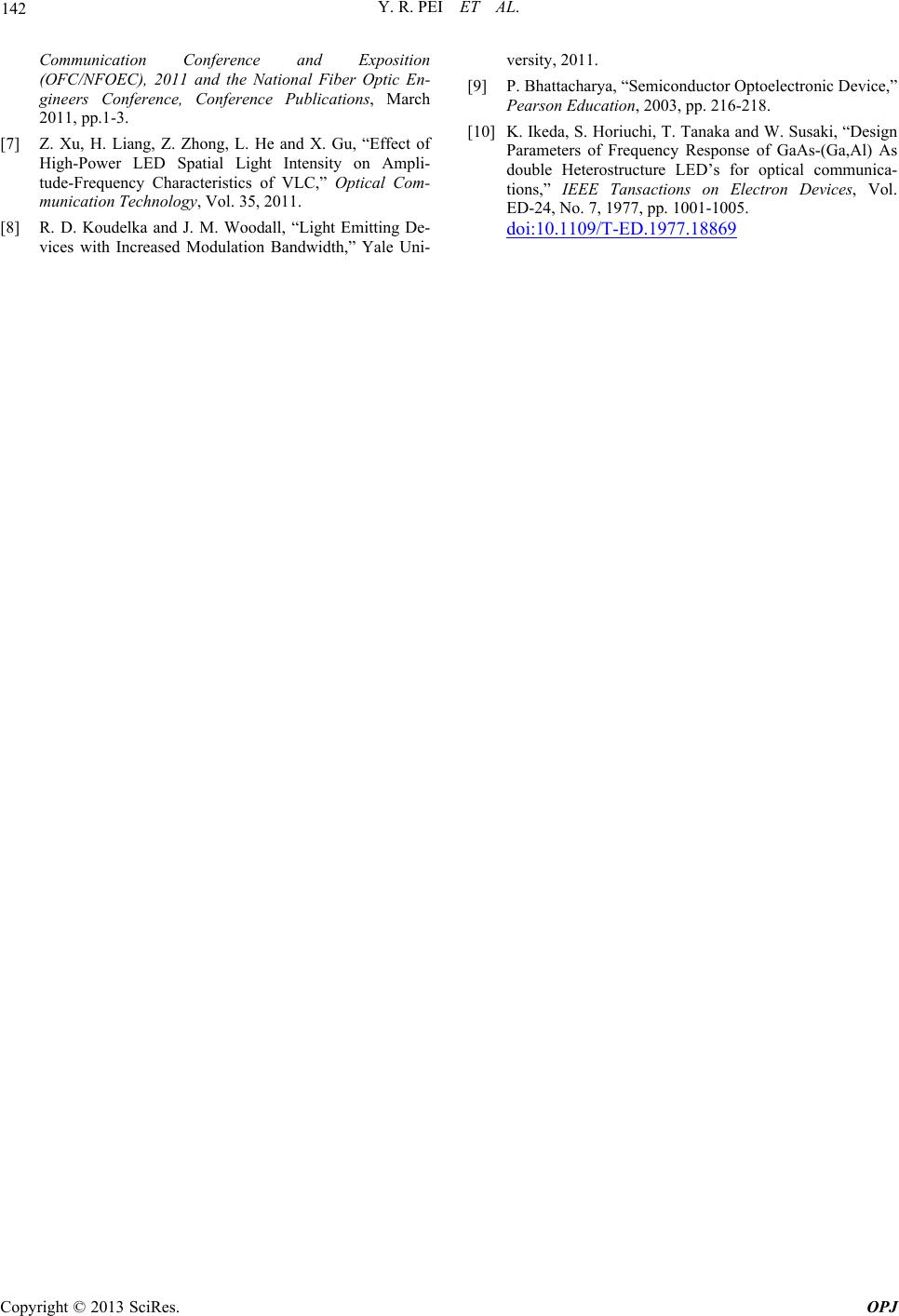
The three different experimental LEDs were divided
into three groups, which were measured under the same
light intensity, and then current density became the only
variable. Therefore, the results can directly reflect the
relationship between current density and the 3 dB band-
width of LED. In Figure 3, the Y coordinates, which is
S21 Amplitude, means that the ratio between output
power and input power and it reflects the 3 dB bandwidth
of LED. Because of the background noise in this experi-
ment, the curves in Figure 3 have large fluctuations.
However, these non-smooth curves are not affecting the
overall trend of the experimental results.
As Figure 3 shows that the 3 dB bandwidth of LED A
was 10.5MHz in the bias current of 20 mA and the value
rapid increased to 44MHz with the bias current of 100mA.
In addition, the LED B and LED C also demonstrated
this rule and the results were shown in Figures 3(b) and
(c), respectively. Therefore, the measured 3dB bandwidth
of three different sizes LEDs were all improved signifi-
cantly with the increased current density. This phe-
nomenon can be demonstrated with the probability of
bimolecular recombination, which was proportional to
the injected carrier density into the active volume [9,10].
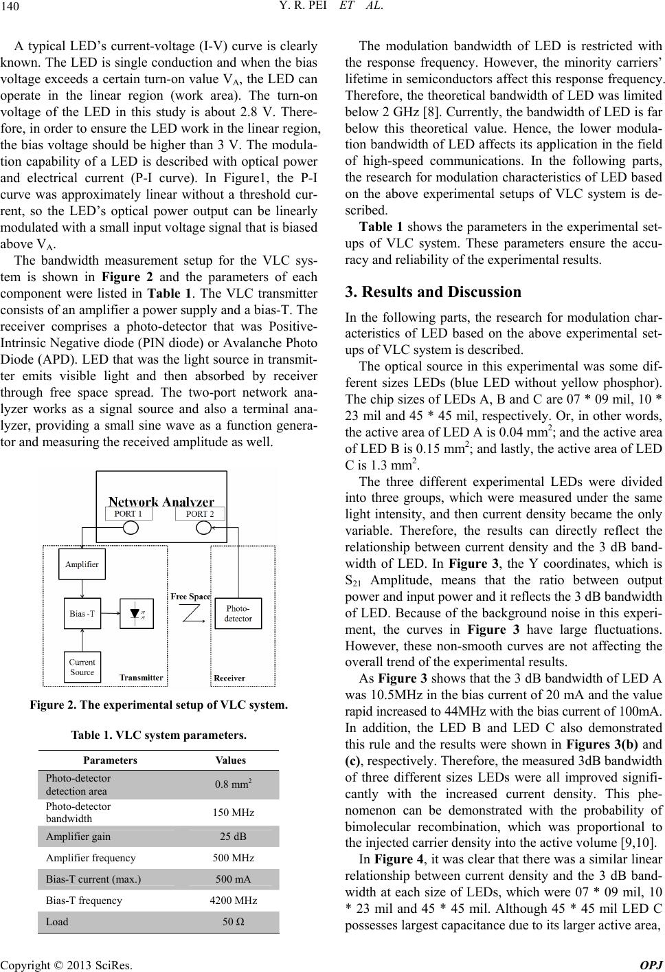
In Figure 4, it was clear that there was a similar linear
relationship between current density and the 3 dB band-
width at each size of LEDs, which were 07 * 09 mil, 10
* 23 mil and 45 * 45 mil. Although 45 * 45 mil LED C
possesses largest capacitance due to its larger active area,
Copyright © 2013 SciRes. OPJ
Y. R. PEI ET AL. 141
(a)
(b)
(c)
Figure 3. The normalized frequency response of (a) LED A,
(b) LED B and (c) LED C measured under different bias
currents.
Figure 4. The diagram of the relationship between current
density and 3 dB bandwidth.
the smaller resistance, which helps to reduce more para-
sitic, thus improve the high speed performance at low
current density. Therefore, high series resistance is one
major issue that limits our LED's modulation speed. To
further improve the LED bandwidth, the resistance can
be reduced by optimizing device layout as well as reduc-
ing material bulk resistance.
These experimental results from the above setups that
further evidence the relationship between 3dB bandwidth
of LED and the current density into LED.
4. Summary and Conclusions
In this paper, a measurement setup of modulation char-
acteristics for VLC systems is described and the band-
widths of different-sized blue LEDs have been reported.
The results clearly reveal a similar linear relationship
between LED current density and its 3dB bandwidth.
This phenomenon can be attributed to the bimolecular
recombination probability that is proportional to the in-
jected carrier density into the active volume. Therefore,
increasing the LED current density is a feasible method
in VLC systems to enhance the data transmission rate.
Moreover, this experiment shows that high series resis-
tance is one major issue that limits our LED's modulation
speed. Thus, further study will focus on optimizing de-
vice layout as well as reducing material bulk resistance to
reduce the resistance.
REFERENCES
[1] H.L. Minh, D. O’Brien, G. Faulkner, L. Zeng, K. Lee, D.
Jung, Y. J. Oh and E. T. Won, “100-Mb/s NRZ Visible
Light Communications Using a Postequalized White
LED” in IEEE Photonics Technology Letters, Vol. 21,
No.15, August 2009.
[2] F. L. Jenq, T. J. Liu and F. Y. Leu, “An AC LED Smart
Lighting System with Visible Light Time-Division Mul-
tiplexing Free Space Optical Communication,” 2011 Fifth
International Conference on Innovative Mobile and
Internet Services in Ubiquitous Computing.
doi:10.1109 /IMIS.2011.6 6
[3] Z. W, J. Chau and T. Little, “Modeling and Designing of
a New Indoor Free Space Visible Light Communication
System,” Networks and Optical Communications (NOC)
in 16th European Conference, July 2011, pp. 72-75.
[4] J. Cao, Z. Liang and Z. Ma, “White LED Modulation
Bandwidth and Modulation Characteristics of the Study”
Hans Journal of Wireless Communications, 2012.
[5] J. Vučić, C. Kottke, S. Nerreter, K.-D. Langer and W.
Waleski, “513 Mbit/s Visible Light Communication Link
Based on DMT-Modulation of a White LED,” Journal of
Light Technology, Vol. 28, No. 24, 2010.
[6] J. Vučić, C. Kottke, K. Habel and K.-D. Langer, “803
Mbit/s Visible Light WDM Link based on DMT Modula-
tion of a single RGB LED Luminary,” Optical Fiber
Copyright © 2013 SciRes. OPJ
Y. R. PEI ET AL.
Copyright © 2013 SciRes. OPJ
142
Communication Conference and Exposition
(OFC/NFOEC), 2011 and the National Fiber Optic En-
gineers Conference, Conference Publications, March
2011, pp.1-3.
[7] Z. Xu, H. Liang, Z. Zhong, L. He and X. Gu, “Effect of
High-Power LED Spatial Light Intensity on Ampli-
tude-Frequency Characteristics of VLC,” Optical Com-
munication Technology, Vol. 35, 2011.
[8] R. D. Koudelka and J. M. Woodall, “Light Emitting De-
vices with Increased Modulation Bandwidth,” Yale Uni-
versity, 2011.
[9] P. Bhattacharya, “Semiconductor Optoelectronic Device,”
Pearson Education, 2003, pp. 216-218.
[10] K. Ikeda, S. Horiuchi, T. Tanaka and W. Susaki, “Design
Parameters of Frequency Response of GaAs-(Ga,Al) As
double Heterostructure LED’s for optical communica-
tions,” IEEE Tansactions on Electron Devices, Vol.
ED-24, No. 7, 1977, pp. 1001-1005.
doi:10.1109 /T-ED.1977.18 869