Journal of Electromagnetic Analysis and Applications
Vol.5 No.2(2013), Article ID:28500,4 pages DOI:10.4236/jemaa.2013.52010
Multi-Band Rectangular Patch End-Fire Antenna Array
![]()
1Department of Electrical and Computer Engineering, Purdue University, West Lafayette, USA; 2Department of Electrical and Computer Engineering, University of Colorado, Colorado Springs, USA.
Email: *hsong@uccs.edu
Received December 7th, 2012; revised January 9th, 2013; accepted January 21st, 2013
Keywords: Multi-Band; End-Fire; Antenna Array; Rectangular Patch Antenna; Wireless Communications
ABSTRACT
A novel multi-band end-fire antenna array was designed, fabricated, and characterized. Analytical calculations were carried out to determine the critical antenna dimensions and the design was optimized using a 3D electromagnetic finite-element solver. The measured results were in good agreement with the designed results. The proposed antenna array exhibits multi-band capabilities which can be potentially used for applications that require a multi-band end-fire radiation pattern.
1. Introduction
Traditional base stations employ omnidirectional antennas where the transmit power is equally radiated in all directions. The equal distribution leads to a portion of the power being transmitted throughout the cell but not received by the user. This wasted power then becomes forward link interference to other base stations or users in other cells. Similarly, each new user added to a cell increases the interference and noise levels on the reverse link. This results in a reduction in the signal-to-noise ratio, which in turn degrades the performance of the detection and demodulation operations. One way to address this problem is in the design of the antenna having multiband end-fire properties with sectorized radiation patterns (wide beamwidths) and high gain (above 5 dBi) in order to create a high front-to-load ratio and alleviate propagation loss effects.
In order to respond to the above need, a novel end-fire antenna array has been investigated using microstrip antenna theory. The microstrip patch antenna was first introduced by Munson in a symposium paper in 1972 [1], which was followed by a journal paper in 1974 [2]. These papers discussed both the wraparound microstrip antenna and the rectangular patch antenna. Since then a plethora of research activity in this area of antenna design began to introduce similar configurations in articles and books, including the microstrip Yagi-Uda array, the microstrip traveling-wave antenna, and the end-fire microstrip log periodic array [3-5]. Microstrip antennas have several well-known advantages over other antenna structures, including their low profile, small size, lightweight, low manufacturing cost, high efficiency, an easy method of fabrication and installation, and compatibility with microwave monolithic integrated circuits (MMICs) and optoelectronic integrated circuits (OEICs) technologies. Because of these merits, various forms of the microstrip patch antenna have been utilized in many applications such as in mobile communication base stations, spaceborne satellite communication systems, and mobile communication handset devices [6].
The rectangular patch end-fire array antenna consists of a half-wavelength by 0.12-wavelength microstrip elements printed on the top substrate layer and connected to a quarter wavelength microstrip corporate feed-line. The ground plane is printed on the bottom substrate. This avoids using a half-wavelength balun, thereby simplifying the antenna geometry. The multi-band behavior is obtained when TM modes can be excited simultaneously. By properly selecting the location of the corporate feed line and optimizing the element width, the antenna can resonant at multiple frequencies [7]. End-fire operation is established by creating a phase difference between the elements at fixed element distances and by the corporate feed network. The desired element phase shifts are then accomplished by the mutual coupling effects. For printed microstrip elements, the mutual coupling can be calculated using practical microstrip antenna theory, thus enabling the analysis of a rectangular patch end-fire array antenna.
In this paper we present the theoretical description and design methods used in modeling the rectangular patch end-fire array antenna. Comparison with the fabricated end-fire patch antenna array is described.
2. Theory
2.1. Phase Difference and Array Factor
End-fire operation is established when the direction of the radiation for the main beam is dependent on the phase difference, α, between the elements of the array. Therefore, it is possible to steer the main beam in any direction by varying α between elements. We start with considering a linear array antenna consisting of N elements, equally interspaced a distance d. The direction of a wave is described by the angle θ between rays and array normal. Therefore, the array factor, AF(θ), for a receiver linear array antenna is given by
 (1)
(1)
where  is the wave number and λ is the wavelength [8]. The phase α is adjusted by including a phase factor
  in the element weight, wn. If the desired steering angle is θ0 the phase difference must be adjusted such that when θ = θ0
 (2)
(2)
thus,
 (3)
(3)
The normalized array factor is given by
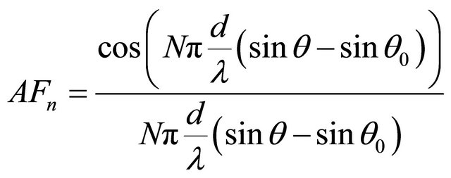 (4)
(4)
So for ψ = 0, an end-fire operation at θ0 = 90˚ and θ = −90˚, respectively, the phase difference, α, between two adjacent elements is [8,9]
 (5)
(5)
and
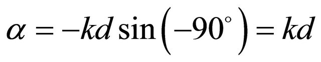 (6)
(6)
2.2. Grating Lobes
High front-to-back ratio is required for an efficient endfire operation. This is achieved by reducing the occurrence of grating lobes to below zero. According to antenna theory, grating lobes occur whenever the argument ψ is an integer multiple of 2π. Therefore, at end-fire operation, grating lobes occur for
 (7)
(7)
For a multi-band linear array antenna we could space the elements as far apart as one wavelength before seeing any grating lobe effects. However, for a linear end-fire array antenna the maximum allowable element spacing is reduced to half a wavelength to prevent the occurrence of grating lobes. If we reduce the element spacing even farther, by less than half a wavelength, the grating lobe at θ = −90˚ becomes less visible.
3. Design
The main advantage of the rectangular patch end-fire array antenna lies in its simplicity of design. This allows for a model-based analysis in a short amount of time and, given some user-defined parameters, the design can be optimized. This antenna was designed and simulated using Ansoft HFSS, a 3-D electromagnetic simulator [10].
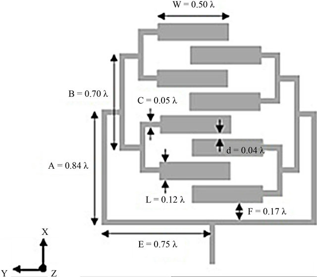
The antenna consists of eight radiating elements connected to a full corporate feed configuration encompassing both branch and main feed. Figures 1(a) and (b) show dimensions and a photo of the proposed fabricated multi-band end-fire array antenna at its optimum RF board configuration, respectively. The resonant frequency for its transverse magnetic (TMmn) mode can be evaluated from [7]
 (a)
(a)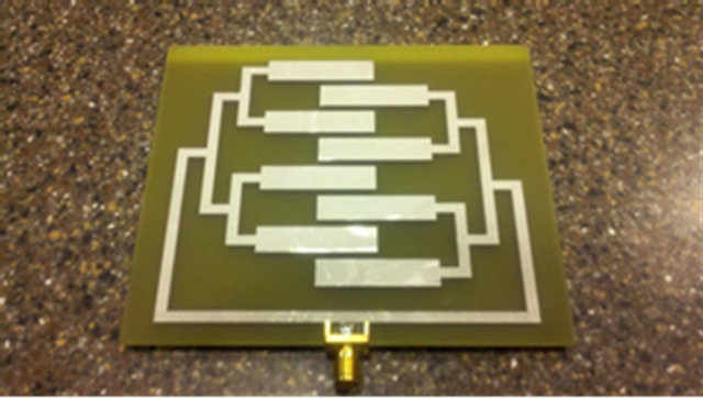 (b)
(b)
Figure 1. (a) Optimized dimensions and (b) photo of the fabricated multi-band end-fire antenna array.
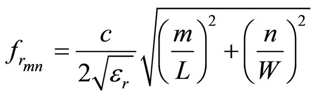 (8)
(8)
where c is the velocity of light; m and n are integers; L and W are the length and width of the patch element, respectively; and εr is the relative permittivity of the substrate. The width of the patch element can be described as [11-13].
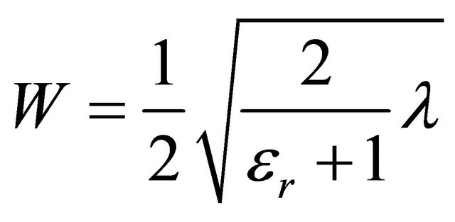 (9)
(9)
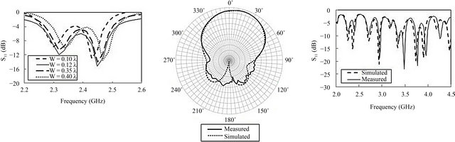
The four lower order modes, namely TM01, TM20, TM30, and TM40, have been predicted by Equation (8) and the resonant frequencies of the proposed antenna changes slightly with the alteration of the width, W, hence, after obtaining rough estimate from Equation (9), HFSS optimization was performed. The optimization process is shown in Figure 2(a). As the width changes from 0.1λ to 0.4λ, the resonant frequency of the excited TM01 mode can be tuned to provide optimum minimum reflection. By placing the main feed at distance 0.17λ of the first element, the additional modes are excited simultaneously, while a width of 0.12λ provides minimum reflection. This results in multi-band behavior. For radiation in the end-fire direction the length of a patch element is determined by
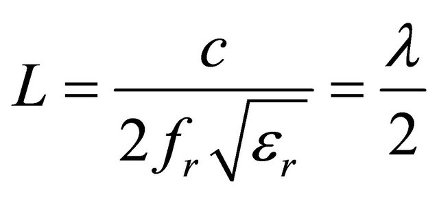 (10)
(10)
Based on the above discussion on antenna width and length, a length of 0.5λ and a width of 0.12λ for the rectangular patch element were chosen.
The element distance, d, that would ensure end-fire operation along the x-y plane was then found. Using Equation (11), where D is the antenna directivity, d in range of 0.04λ to 0.05λ was found and then optimized with HFSS [14]. The optimized value of d yielded 0.04λ.
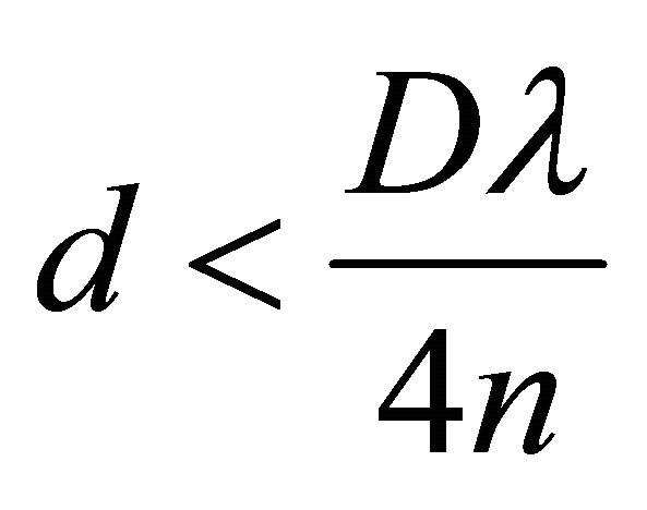 (11)
(11)
The rest of the dimensions (A, B, C, E and F) were determined using HFSS optimization routine.
4. Measured Results
To verify the analysis presented for this antenna structure, the antenna was measured. The design was fabricated by Advanced Circuits, and measured in the microwave laboratory of the Engineering and Applied Science (EAS) building at the University of Colorado at Colorado Springs. The antenna was fabricated in FR-4 substrate with a dielectric constant of 4.25 and a thickness of 62 mils. The radiation pattern was measured in the anechoic chamber of the EAS building. The antenna was mounted on a polystyrene foam platform with a standard clear tape and connected to a coaxial cable. The antenna-under-test (AUT) served as the receiving antenna, while a rectangular horn antenna was used to transmit the wave. Due to the design of the platform, only an E-plane measurement in the range of −178˚ ≤ θ ≤ 178˚ could be taken. This was sufficient to compare the main beam and the backside radiation level. Figure 2(b) shows simulated and measured radiation patterns for the multi-band end-fire antenna array in an azimuthal plane (end-fire direction at θ = 90˚ and −90˚ plane, which is the x-y plane shown in Figure 1(a)) at 2.45 GHz. The measured maximum gain was 6.9 dBi in the end-fire direction, which was in good agreement with the simulation result. For the return loss measurement, an edge-mounted SMA connector was soldered to the edge of the board, and measured on a network analyzer at a frequency sweep from 2.0 to 4.5 GHz. Figure 2(c) shows the simulated and measured S11 of
 (a) (b) (c)
Figure 2. (a) Simulation results showing the S11 as a function of frequency for different width (W) values; (b) Radiation pattern measured in end-fire direction (shown in Figure 1(a) as θ = 90˚ and −90˚ in the x-y plane) at 2.45 GHz; (c) Measured and simulated S11 of the multi-band end-fire antenna array.
the multi-band end-fire antenna array. The proposed antenna produces an end-fire beam and is matched over a multi-band in the frequency range of 2.0 to 4.5 GHz. Multi-dips in S11 were measured, which includes impedance matching at frequencies of 2.9, 3.4, 3.7 and 3.9 GHz.
5. Conclusions and Discussion
The design, fabrication and characterization of a rectangular patch end-fire array antenna were presented. The antenna was designed and optimized using eight elements of half-wavelength and a width 0.12λ in FR-4 substrate. Measured results showed end-fire operation with a measured maximum gain of 6.9 dBi in the end-fire direction. The proposed antenna can be employed for multiband applications that require a radiation pattern in the end-fire direction.
Although the research achieved its objectives, the antenna has an inherent limitation in its pure form. Namely, if the end-fire array is confined to operate in receiving mode, detuning may occur should changes in climatic or atmospheric conditions develop. Additional testing, such as the Over-the-Air (OTA) testing, could be conducted in order to accurately measure the antenna’s performance in environmental conditions. Furthermore, in the radiation pattern measurement, the operating frequency was limited to operate at a single frequency. By measuring additional radiation patterns at each of the frequencies shown in Figure 2(c), the results could provide additional data to support the antenna’s overall efficiency; where the portion of the power supplied to the antenna, including any reflection loss, is actually radiated by the antenna.
REFERENCES
- R. E. Munson, “Microstrip Phased Array Antennas,” Proceedings of Twenty-Second Symposium on USAF Antenna Research and Development Program, 11-13 October 1972.
- R. E. Munson, “Conformal Microstrip Antennas and Microstrip Phased Arrays,” IEEE Transactions on Antennas Propagation, Vol. AP-22, No. 1, 1974, pp. 74-78. doi:10.1109/TAP.1974.1140723
- M. Bemani and S. Nikmehr, “A Novel Wide-Band Microstrip Yagi-Uda Array Antenna for WLAN Applications,” Progress in Electromagnetic Research B, Vol. 16, 2009, pp. 389-406. doi:10.2528/PIERB09053101
- E. Ojefors, S. Cheng, K. From, I. Skarin, P. Hallbjorner and A. Rydber, “Electrically Steerable Single-Layer Microstrip Traveling Wave Antenna with Varactor Diode Based Phase Shifters,” IEEE Transactions on Antennas and Propagation, Vol. 55, No. 9, 2007, pp. 2451-2460. doi:10.1109/TAP.2007.904104
- P. S. Hall, “Endfire Microstrip Log Periodic Array,” Antennas and Propagation Society International Symposium, Vol. 2, 1988, pp. 434-437.
- R. Waterhouse, “Microstrip Patch Antennas: A Designer’s Guide,” Kluwer Academic Publishers, Norwell, 2005.
- H. E. King, “Mutual Impedance of Unequal Length Antennas in Echelon,” IRE Transactions on Antenna and Propagation, Vol. 5, No. 3, 1957, pp. 306-313. doi:10.1109/TAP.1957.1144509
- H. Visser, “Array and Phased Array Antenna Basics,” John Wiley & Sons, New York, 2005. doi:10.1002/0470871199
- K. L Wong, “Compact and Broadband Microstrip Antennas,” John Wiley & Sons, Hoboken, 2002. doi:10.1002/0471221112
- http://www.ansoft.com/products/hf/hfss/
- C. A. Balanis, “Antenna Theory: Analysis and Design,” John Wiley & Sons, Hoboken, 2005.
- R. Garg, “Microstrip Antenna Design Handbook,” Artech House, London, 2001.
- T. A. Milligan, “Modern Antenna Design,” John Wiley & Sons, Hoboken, 2005. doi:10.1002/0471720615
- U. A. Bakshi, A. V. Bakshi, and K. A. Bakshi, “Antenna & Wave Propagation,” Technical Publications, Pune, 2008.
NOTES
*Corresponding author.