Journal of Electromagnetic Analysis and Applications
Vol.4 No.6(2012), Article ID:20335,8 pages DOI:10.4236/jemaa.2012.46033
Analysis of the Radiation Resistance and Gain of Full-Wave Dipole Antenna for Different Feeding Design
![]()
1Electrical and Electronics Department, Al-Huson university College, Al-Balqa’ Applied University, Irbed, Jordan; 2College of Technology and Innovation (UCTI), Asia Pacific University, Technology Park Malaysia (TPM), Kuala Lumpur, Malaysia; 3Electrical and Electronics Department, Amman Faculty of Engineering, Al-Balqa’ Applied University, Amman, Jordan.
Email: yahya@huson.edu.jo, dr.khedher@ucti.edu.my, anwar1971@yahoo.com
Received April 4th, 2012; revised May 2nd, 2012; accepted May 12th, 2012
Keywords: Full-Wave Dipole Antenna; Radiation Pattern; Gain; Double Feeding and Triple Feeding
ABSTRACT
This paper demonstrates the analysis of antenna pattern and gain for different designs of full-wave dipole antenna feeding techniques. Seven such techniques were studied and analyzed; symmetrical dual feeding in phase, symmetrical dual feeding out of phase, asymmetrical dual feeding in phase, asymmetrical dual feeding out of phase, symmetrical triple feeding in phase and symmetrical triple feeding out of phase. Symmetrical dual feeding in phase produced high gain as compared to the single and center-fed antennas. An improvement of about 3 to 3.5 dB was achieved comparing to center tap fed and off center fed. It was found that an asymmetrical dual feeding in-phase provides good performance, considering the directivity, pattern, and input impedance. A 2.46 dB gain has been obtained. It was found that a symmetrical triple feeding provides an overall best performance with respect to gain, radiation pattern, beam width and input impedance.
1. Introduction
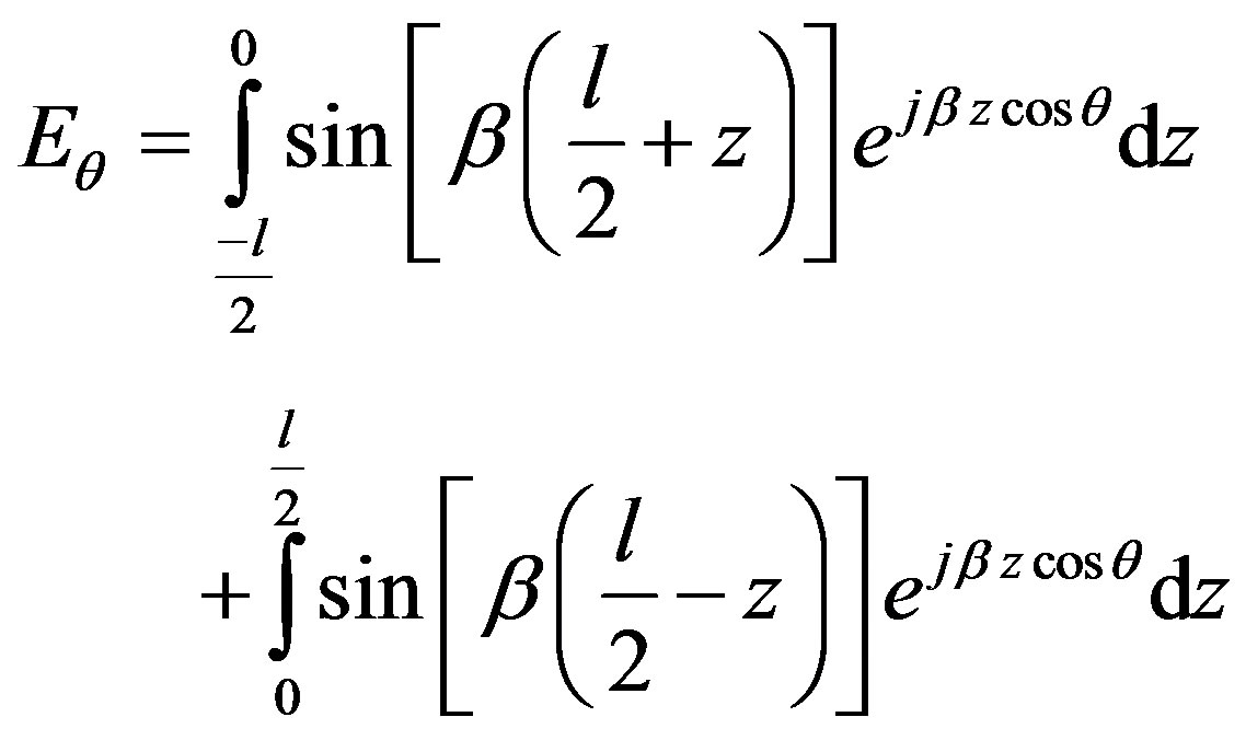
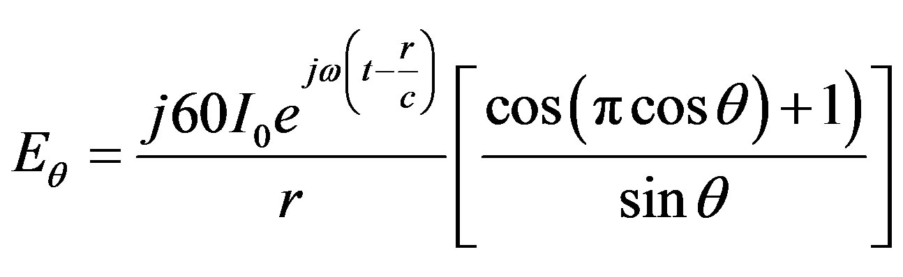
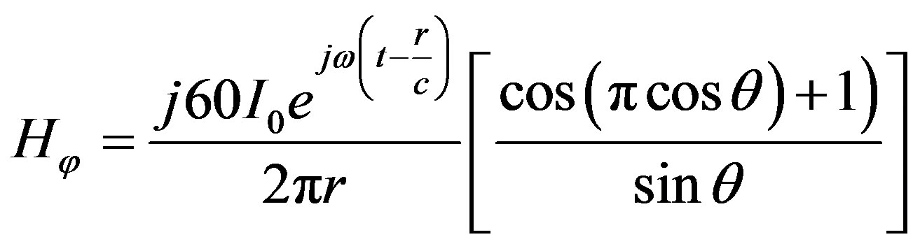
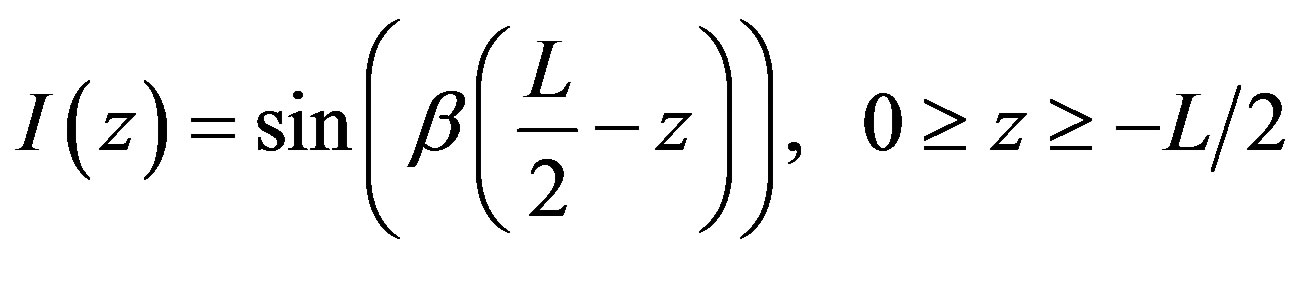
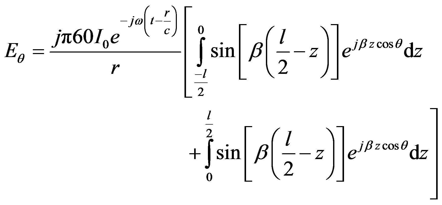
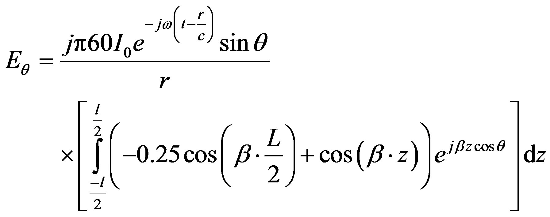
According to the thin wire approximation and Maxwell Equations, the z-component of the radiated electric field for infinitesimal dipole is shown in Figure 1 and depicted in equation (1) [1,2].
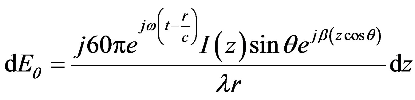 (1)
(1)
A Matlab computer code was written to simulate the pattern performance of the antenna at any scan angle. This program can be used to facilitate further study of the antenna. The computed patterns from this program are compared to the measured patterns as a means for validating the model [3]. Some special attributes of the software are: the simulation through the straight calculation of the fields, the analysis of sensitivity and the behavior against frequency changes and the use of the current distribution on the dipole calculated by the Method of Moments, King’s Approximation, and Hallen’s solution. In this simulation, it was assumed that the dipole consists of two collinear wires separated by a small gap where the excitation is applied. Ideally, the values of gap and the diameter of the wires have to be zero but practically it can be considered as a continuous a thin filament. In the far zone region, the electric field was produced by the dipole considering an ideal sinusoidal current distribution.
In [4] different equations for the current distribution were obtained. These equations were used to derive the radiation pattern of Antenna A1, A2, B1, B2, C1, C2, and C3.
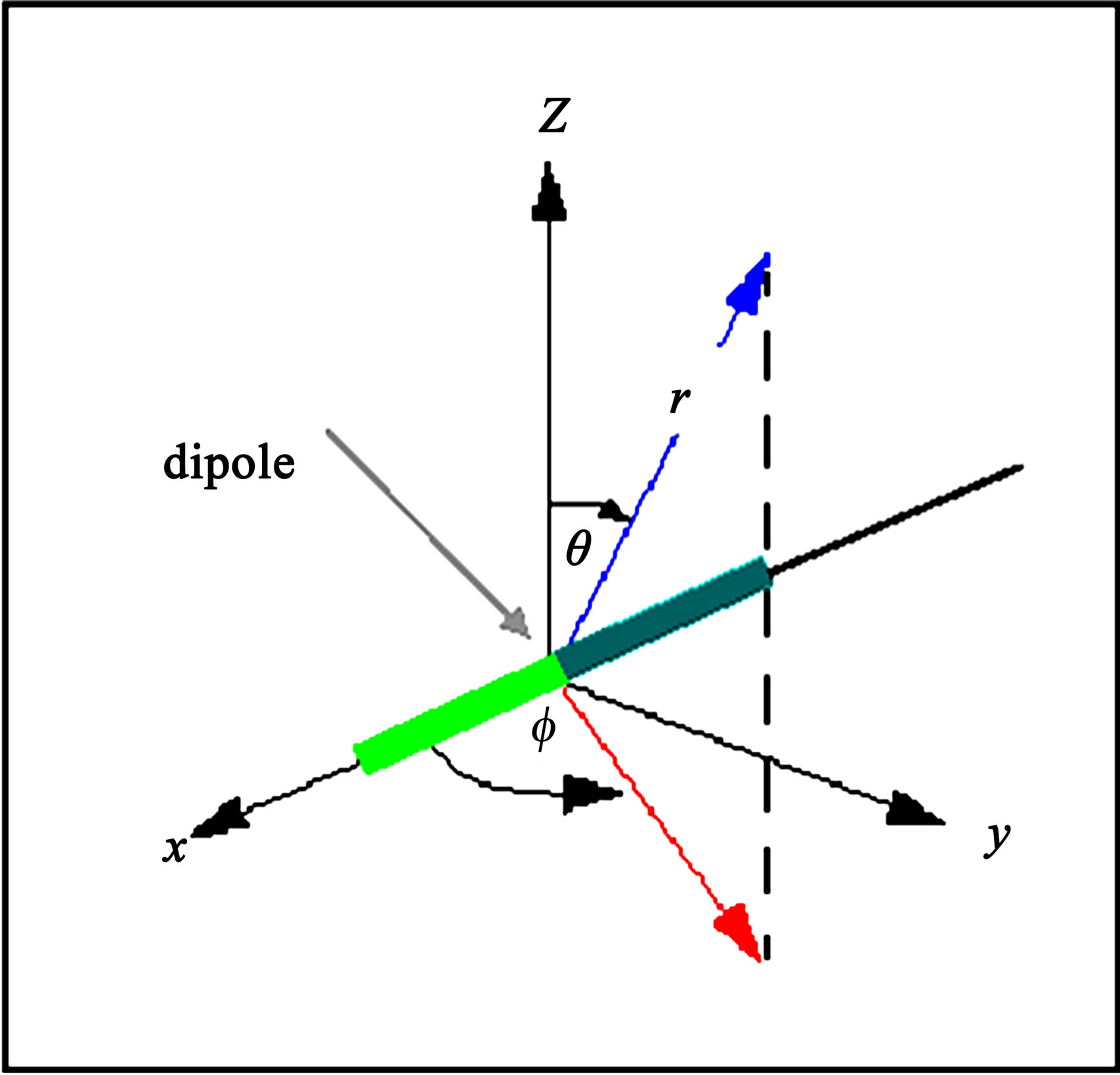
Figure 1. Coordinate system used with antennas.
2. Radiation Pattern of Our Designed Antennas
2.1. Antenna A1
The feeding arrangements for the symmetrical dual feeding in phase (Antenna A1) is shown in Figure 2.
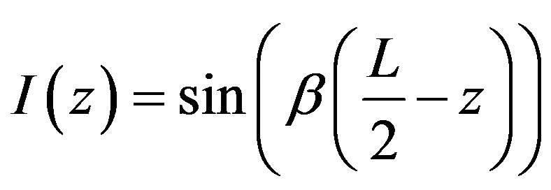
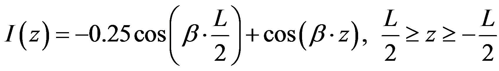
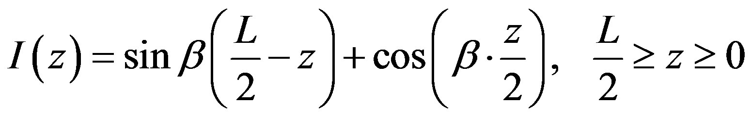
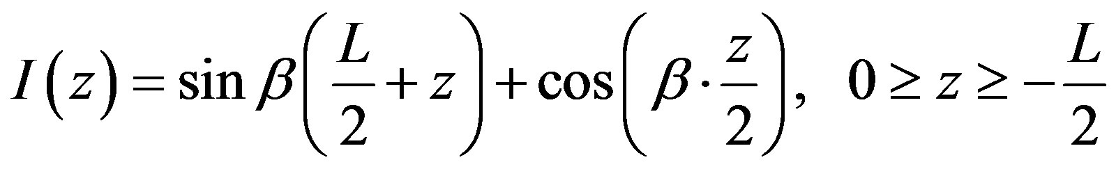
Expression of the current distribution is as given below:
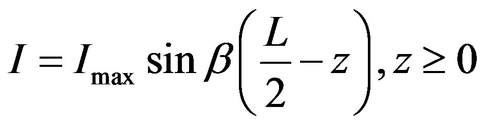 (2)
(2)
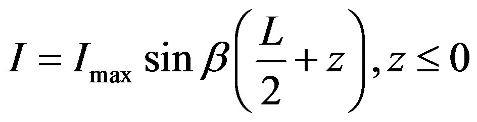 (3)
(3)
where .
.
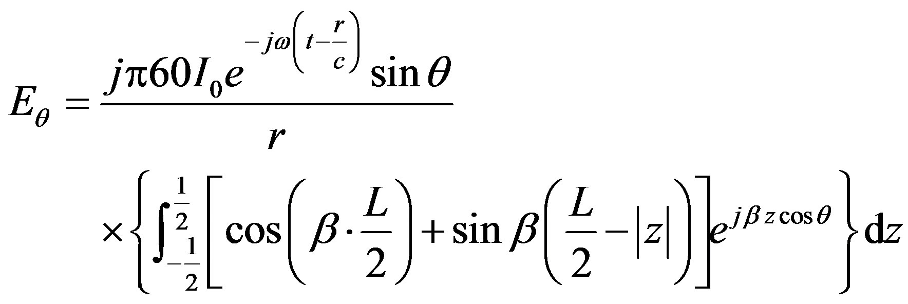
Substituting Equations (2) and (3) in (1), yields
 (4)
(4)
Using Equation (5) solve the Equation (4) gives Equation (6)
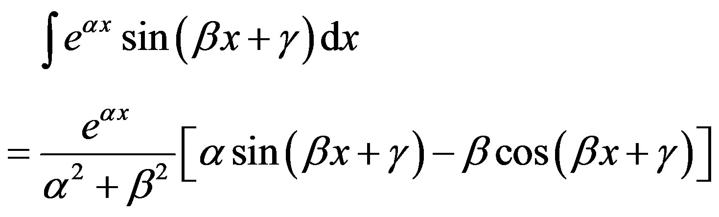 (5)
(5)
 (6)
(6)
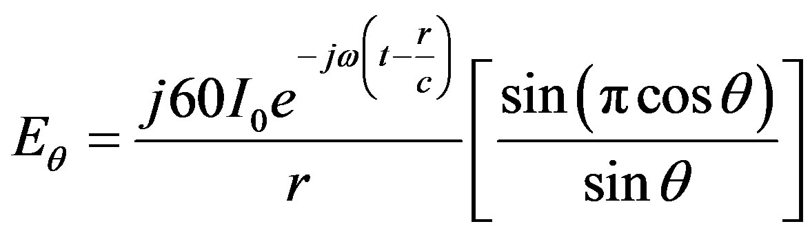
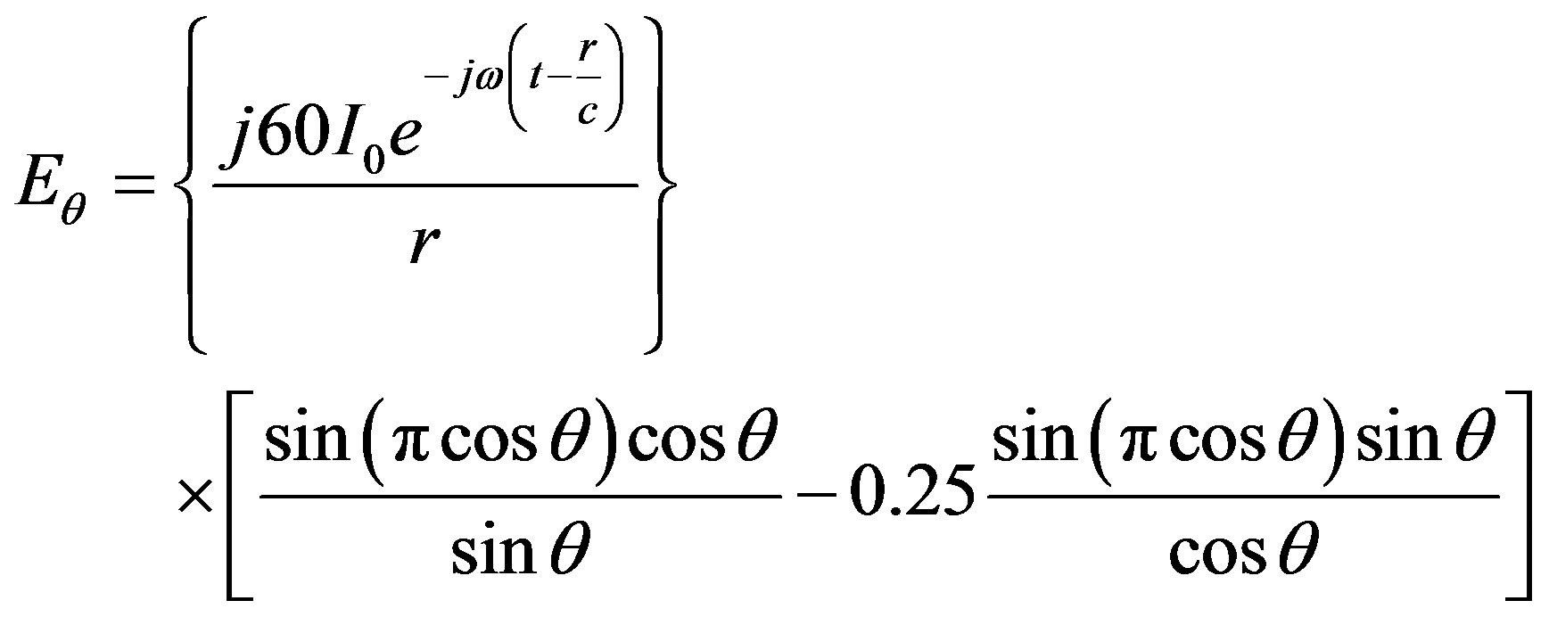
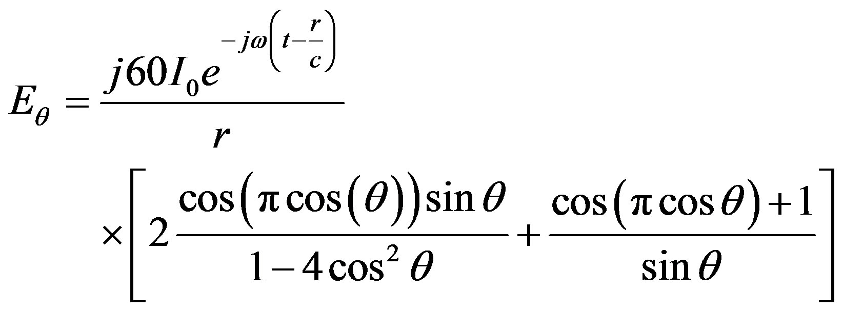
In this study L = λ = 1 m. Substituting λ = 1 and simplifying Equation (6) yields
 (7)
(7)
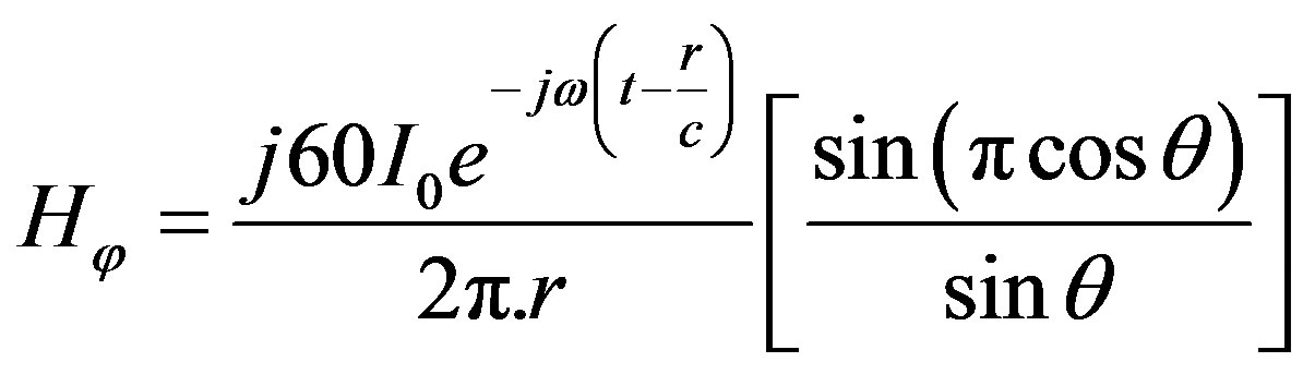
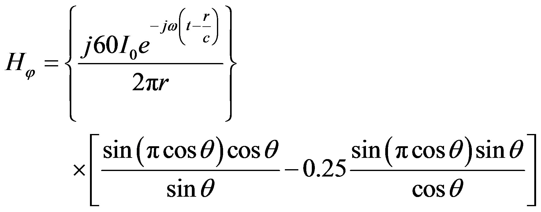
 (8)
(8)
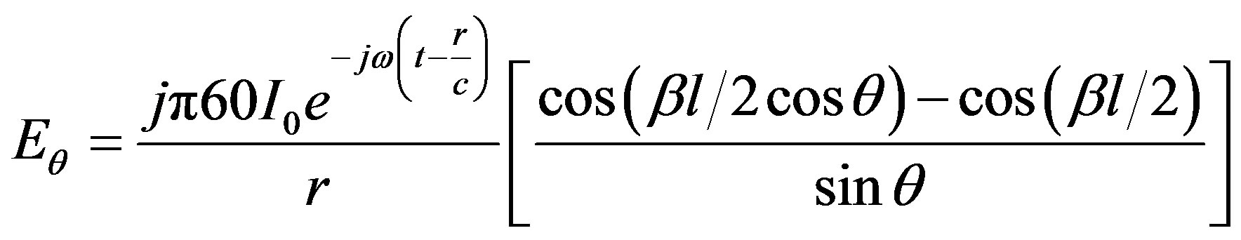
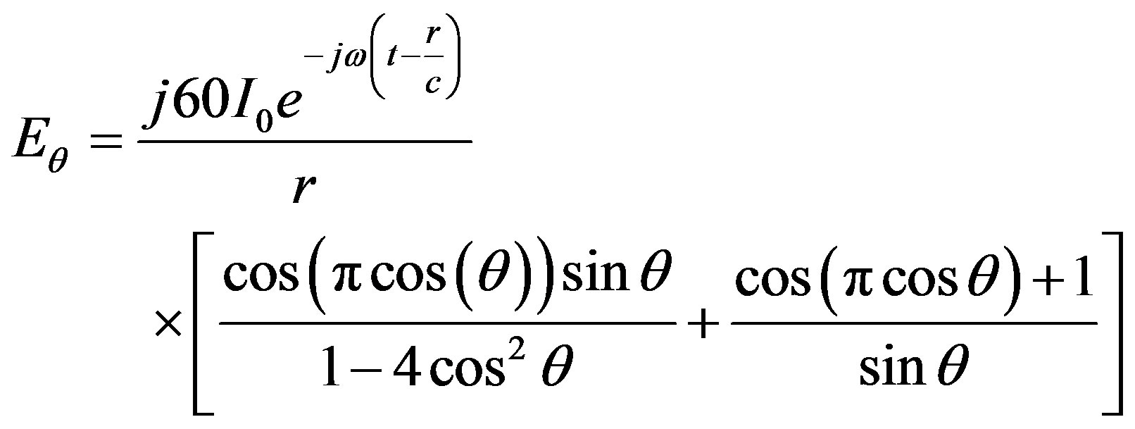
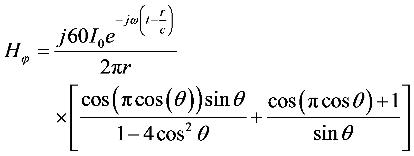
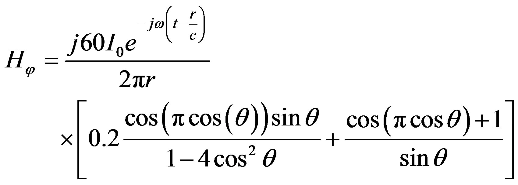
Equations (7) and (8) represent the electric and magnetic field components of Antenna A1. The equation of the radiation pattern for Antenna A1 is depicted in Equation (7) and from this equation; the radiation pattern can be plotted as shown in Figure 3.
The dual feeding technique has given a radiation pattern, which is different from those of center fed and off center fed due to the phase reversal at the midpoint of Antenna A1, and this technique splits the radiation pattern into two main lobes, which contribute to a highly directive radiation pattern on the broadside of the plane of the antenna. The two feeding points are in-phase, and that leads the antenna to give a high profile of gain due to current distribution that has two maximum peaks. The maximum peaks are positive, resulting in radiation pattern to be split into two main lobes.
2.2. Antenna A2
The feeding arrangements for symmetrical dual feeding out of phase (Antenna A2) is shown in Figure 4.
The mathematical expression of the current distribution of this antenna is shown in Equations (9) and (10)
 ,
, (9)
(9)
 (10)
(10)
Equations (9) and (10) represent the current distribution over the three arms of Antenna A2. Substituting Equations (9) and (10) in (1), yields
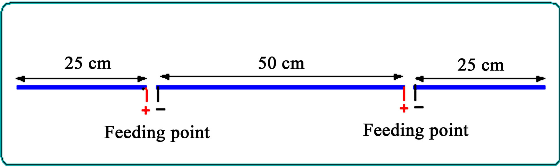
Figure 2. Feeding arrangements for symmetrical dual feeding in Phase antenna.
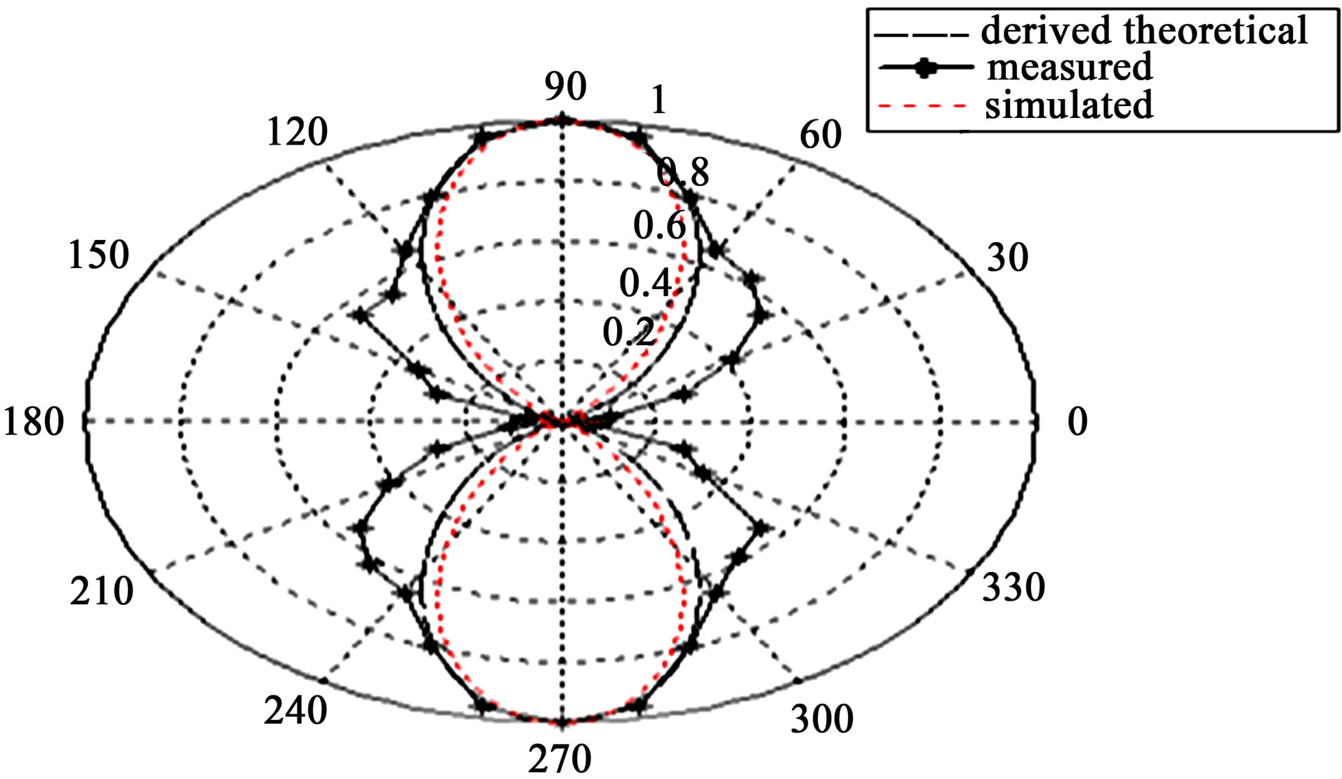
Figure 3. Radiation pattern of antenna A1.
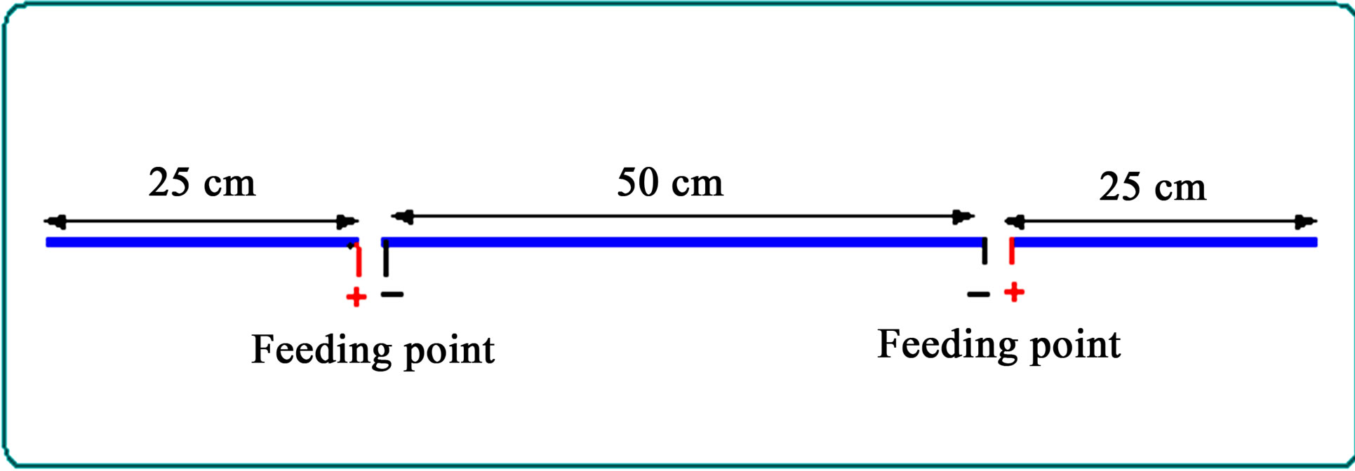
Figure 4. Feeding arrangements for symmetrical dual feeding out of phase antenna.
 (11)
(11)
Solving Equation (11) using Math Cad and Matlab; we have Equations (12) and (13). Equations (12) and (13) represent the electric and magnetic field components of Antenna A2.
 (12)
(12)
 (13)
(13)
Figure 5 shows the radiation pattern of Antenna A2. The technique of dual feeding out-of-phase produced the same radiation pattern as unbalanced single feeding, but still Antenna A2 gives high performance as compared to single center-fed, or off-center fed antenna.
The two feeding points are out-of-phase, which makes the antenna to change its characteristics to give lower profile of gain as compared to Antenna A1, which can be attributed to current distribution. This current distribution has two peaks, one is positive and the other is negative and that led the radiation pattern to be split into four lobes. According to ARRL, the signal strength depends on how the signals, radiated from the antenna’s electrons, add up in the observer’s antenna. Some of the signals would add up and the rest cancel out. The quantity of adding and canceling depends on the phase of the received signals and their relative amplitudes. Antenna A2 has the same characteristics like that of a full-wavelength antenna as composed of two half-wavelength antennas with identical radiating properties. One excited positively and the other, negatively, or 180 out-of-phase, it exhibits maxima along the positive and negative z-axis, and nulls, in the x-y plane where the contributions from the two elements cancel out because they are out of phase. The radiation pattern of an antenna A2 shows what signal strength would be received by changing the polarity of the feeding.
2.3. Antenna B1
The feeding arrangements for the asymmetrical dual feeding out of phase (Antenna B2) is shown in Figure 6.
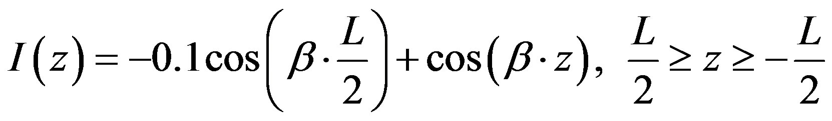
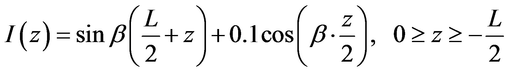
The Equation for measured current distribution can be expressed as shown below:
 (14)
(14)
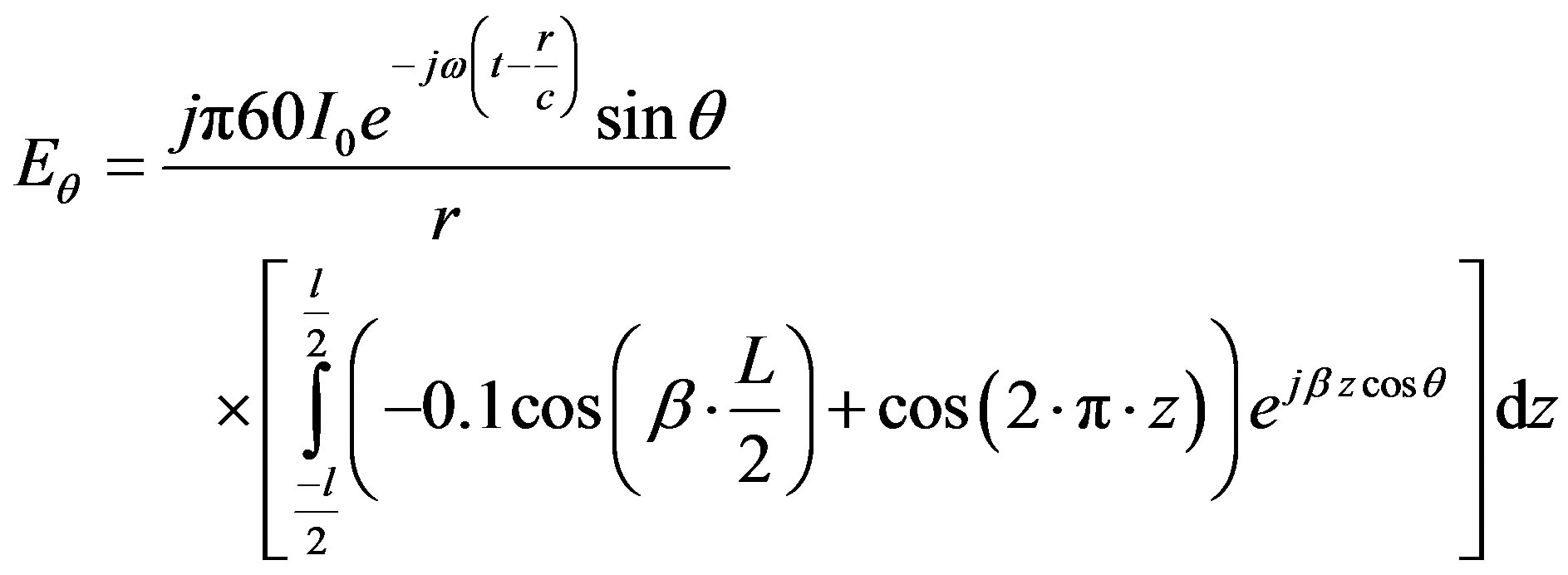
Substituting Equation (14) in equation (1), yields
 (15)
(15)
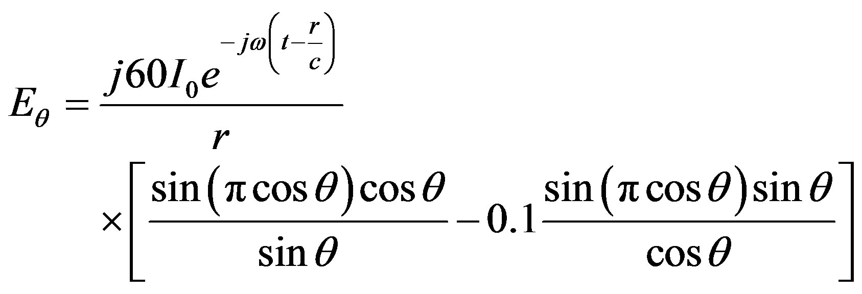
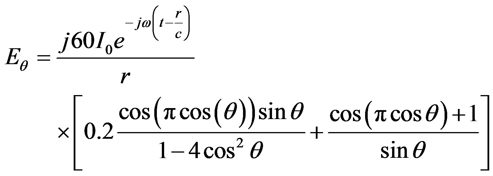
Solving Equation (15), we have Equations (16) and (17) which represent the electric and magnetic field components of Antenna B1 respectively.
In asymmetrical dual feeding configuration, one feed-
 (16)
(16)
 (17)
(17)
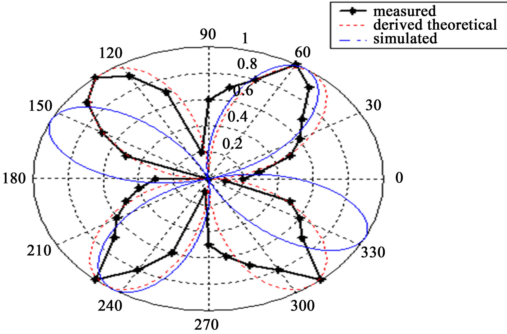
Figure 5. Radiation pattern of antenna A2.
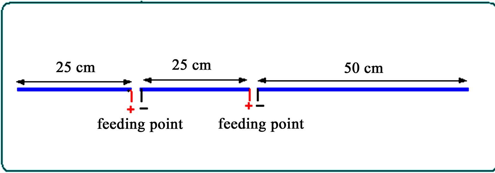
Figure 6. Feeding arrangements for asymmetrical dual feeding in phase antenna.
ing point is located at quarter wavelength away from the center and the other is located at the center of the fullwave dipole. The current distribution has three such peaks. Two negative peaks flowing in same direction are inphase, while the main one in the middle, flowing in opposite direction and is out-of-phase. Figure 7 shows the radiation pattern of Antenna B1, which consists of four main lobes, and two grating small lobes due to effect of the current stored at the end of the antenna causing reactance impedance at the feeding points. Willard, stated that the value of the feed point reactance is not as accurate as the feed point resistance. The four lobes in measured pattern are not shown, due to the percentage of error. The standard dipole has a rated accuracy of 0.5 dB, which was translated into an accuracy of 19% [5].
However, it is consistency among the measured, simulated, and theoretical analyses. In Matlab simulator, the diameter was assumed to be very small (Zero). In this simulation, the diameter is 0.02 λ, and the diameter in King’s approximation is 10–4 λ. For this reason, a slight discrepancy was noted between simulated and theoretical analyses.
2.4. Antenna B2
The feeding arrangements for the asymmetrical dual feeding out of phase (Antenna B2) is shown in Figure 8.
The Equation for measured current distribution can be expressed as shown below:
 (18)
(18)
Substituting Equation (18) in equation (1), yields
 (19)
(19)
 (20)
(20)
 (21)
(21)
For Antenna B2, the equation of the radiation pattern has been split into four main lobes and two minor small lobes because the cosine coefficient factor M, is –0.1, leading the equation of the current distribution to have two peaks in negative zone and one peak in positive zone. The capacitive characteristics increased due to change in polarity of the feeding applied to Antenna B2. The gain has dropped due to current distribution characteristics. The radiation pattern is split into four lobes and two nulls due to the stored charge at the ends of the Antenna B2. Figure 9 shows the radiation pattern of Antenna B2.
Figure 7. Radiation pattern of antenna B1.
Figure 8. Feeding arrangements for asymmetrical dual feeding out of phase antenna.
Figure 9. Radiation pattern of antenna B2.
Tang and Gunn, showed that the radiation pattern of an antenna with large capacitive load impedance changes in shape when the current distribution changes in shape and its peak moves away from the feed points. The radiated power density may fall into well-defined regions called lobes, separated by regions of low intensity called nulls. However, the nulls can only be seen for some particular directions [6]. There are main lobes, which are usually where the desirable power from the antenna is directed, and side lobes where the antenna sends radiated energy. This energy is regarded as wasted or may even interfere with other transmitting systems. It is possible to have more than one main lobe having a given maximum value of gain. For example, a linear array of dipoles can have main lobes 180˚ apart, and both having the same gain [7].
2.5. Antenna C1
The feeding arrangements for symmetrical triple feeding in phase (Antenna C1) is shown in Figure 10.
The current distribution for Antenna C1 can be expressed as in Equations (22) and (23), where M is the coefficient of cosine factor. M is variable depending on the method of feeding. For antenna C1 the coefficient of cosine factor is equal to 1.
 (22)
(22)
 (23)
(23)
Substituting Equations (22) and (23) in Equation (1), yields
 (24)
(24)
The evaluation of Equation (24) yields
 (25)
(25)
 (26)
(26)
Equations (25) and (26) represent the electric and magnetic field components of Antenna C1 respectively. Figure 11 shows the radiation pattern of Antenna C1.
2.6. Antenna C2
The feeding arrangements for symmetrical triple feeding out of phase (Antenna C2) is shown below in Figure 12.
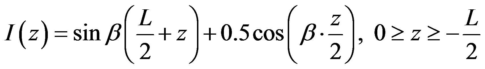
For Antenna C2, the coefficient of cosine factor M is equal to 0.5. Thus, the equation of the current distribution for triple feeding Antenna C2 is expressed mathematically as given in Equations (27) and (28).
 (27)
(27)
Figure 10. Feeding arrangements for triple feeding full wave antenna.
Figure 11. Radiation pattern of antenna C1.
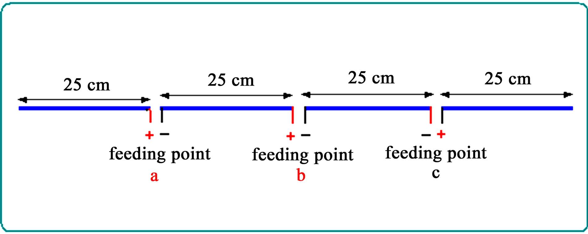
Figure 12. Feeding arrangements for triple feeding full wave antenna.
 (28)
(28)
The characteristics of current distribution of Antenna C2 is similar to that of Antenna C1, except the second function of Equations (27) and (28) is multiplied by 0.5, thus the numerical analysis and the calculation of the parameters of Antenna C2 could be calculated following the same procedure of analysis and calculation as of Antenna C1. Substituting Equations (27) and (28) in equation (1), gives Equations (29) and (30) which represent the electric and magnetic field components of Antenna C2 respectively. Figure 13 shows the radiation pattern of Antenna C2.
 (29)
(29)
 (30)
(30)
2.7. Antenna C3
The feeding arrangements for symmetrical triple feeding out of phase (Antenna C3) is shown in Figure 14.
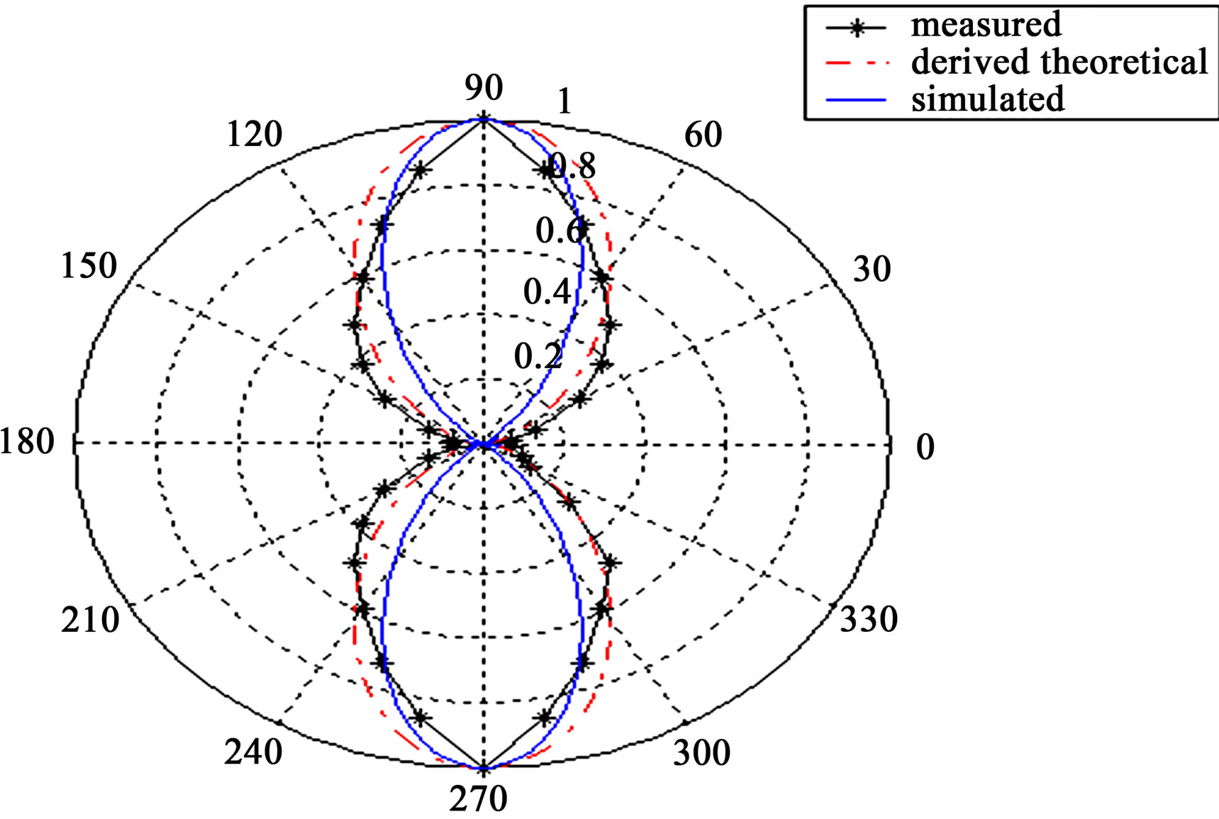
Figure 13. Radiation pattern of antenna C2.
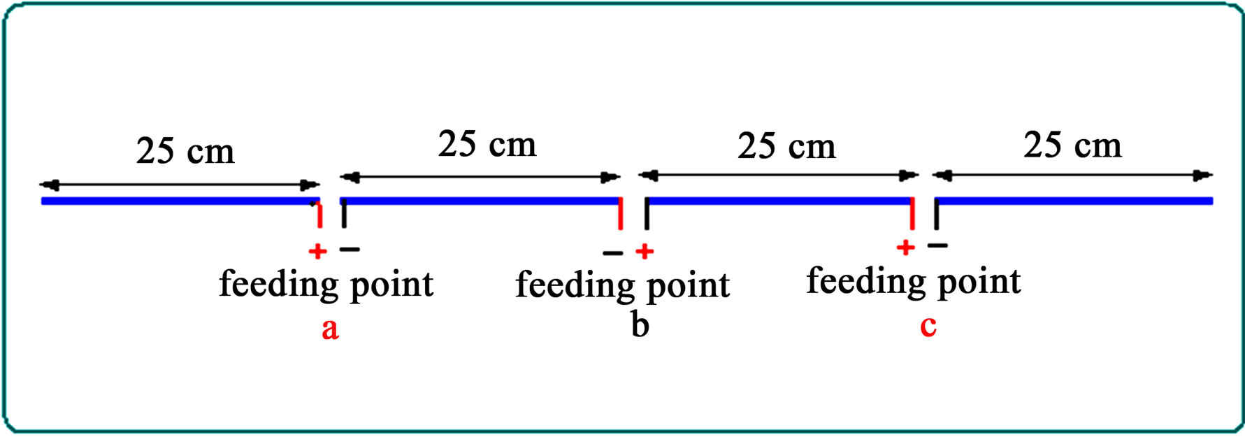
Figure 14. Feeding arrangements for triple feeding full wave antenna.
The mathematical expression for the current distribution is indicated in Equations (31) and (32); taking into consideration that coefficient of cosine factor is equal to 0.1 for Antenna C3.
 (31)
(31)
 (32)
(32)
Substituting Equations (31) and (32) in Equation (1), and solving following the same procedure, yields Equations (33) and (34) which represent the electric and magnetic field components of Antenna C3 respectively. Figure 15 shows the radiation pattern of Antenna C3.
 (33)
(33)
 (34)
(34)
The equations of the radiation pattern for Antenna C1, C2 and C3 are derived based on the obtained equations of the current distribution. The equation of the radiation pattern for symmetrical triple feeding can be generalized as depicted in Equation (35)
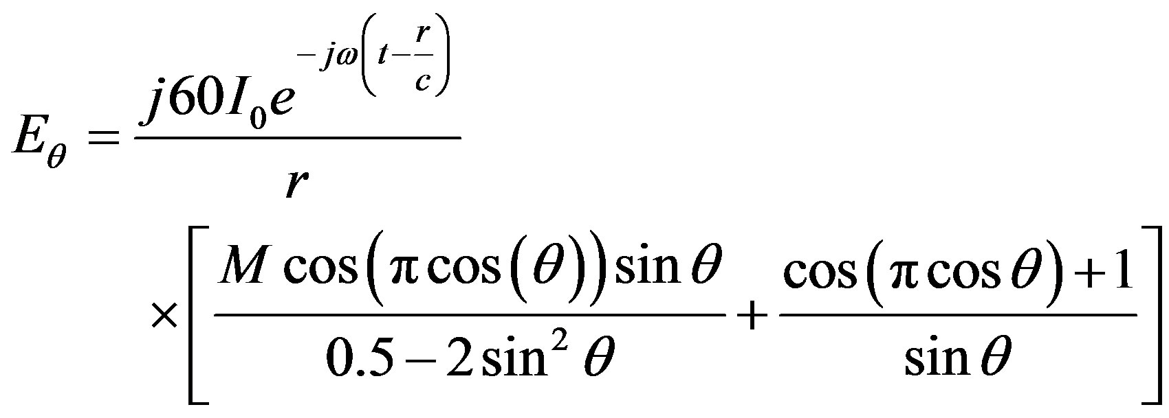 (35)
(35)
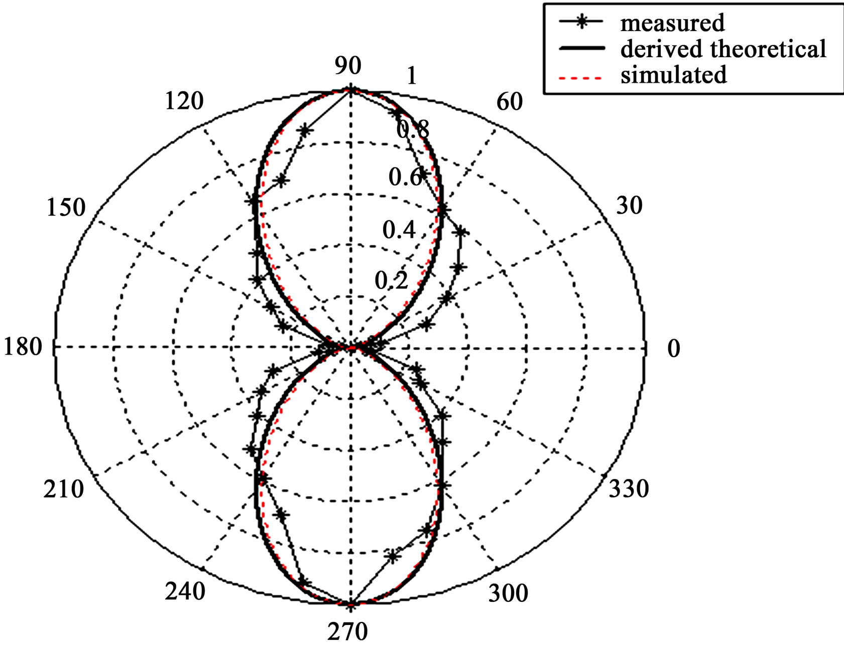
Figure 15. Radiation pattern of antenna C3.
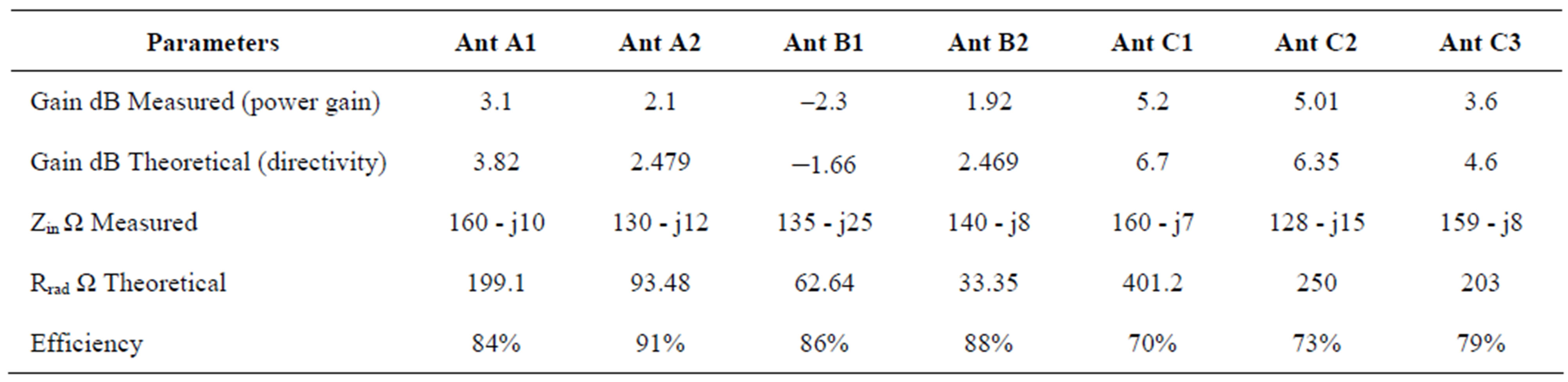
Table 1. Measured and theoretical parameters of full wave antenna.
Equation (35) is derived for the radiation pattern of symmetrical triple feeding, which is valid for symmetrical triple feeding for full-wave antenna regardless of the length and width of antenna. The validity of this Equation for asymmetrical triple feeding needs further examining, and strict investigations as is mentioned in previous section. Moreover, according to [8], the asymmetrical feeding produces the input impedance, which is a combination of real and imaginary values. Whereas, for symmetrical triple feeding antenna produces the input impedance, which is pure resistance. Since, in asymmetrical feeding, the ratio between the peak current and the drive current can be even greater than 2 and the current doesn’t fall to the zero at the end of the antenna. However, the analysis of the radiation pattern shows an appreciable agreement among the measured, simulated and theoretical analyses.
3. Gain and Efficiency
For Antenna A1, the symmetrical dual feeding technique produced high gain as compared to the single and centerfed antennas. An improvement of about 3 to 3.5 dB was achieved comparing to center tap fed and off center fed.
However, this increase in directivity is at the cost of increasing the feed of the antenna. For Antenna A2, when the polarity of feeding changes, the gain drops because the radiation pattern is split into four lobes, but Antenna A2 still gives better results as compared to single-fed, with respect to gain and input impedance. The effects of the asymmetrical feeding on radiation characteristics were investigated. As shown in Table 1 and comparing to single off-center feeding, it was found that an asymmetrical dual feeding in-phase (Antenna B2) provides good performance, considering the directivity, pattern, and input impedance. A 2.46 dB gain has been obtained. The investigation of the asymmetrical dual feeding out-of-phase indicated that this antenna actually has a lesser gain than the single center-fed and single off-center fed and lower input impedance at the input feeding ports. However, the gain of Antenna B1 is dropped apparently because the radiation pattern has 6 lobes. It was found that a symmetrical triple feeding provides an overall best performance with respect to gain, radiation pattern, beam width, and input impedance an expression for efficiency is given:
 5.94 where D is the theoretical gain (Directivity) of the antenna, and G is the measured gain (Power Gain). The efficiency of Antennas A1, A2, B1, B2, C1, C2, and C3 is indicated in Table 1
4. Conclusion
The Analysis of the radiation pattern and gain of different feeding design of full-wave dipole antenna were discussed and presented. The symmetrical dual feeding in phase as well as the symmetrical triple feeding in phase provided the best performance and results comparing to center tap fed and off center fed. The theoretical and measured results of both gain and input impedance were presented.
REFERENCES
- C. A. Balanis, “Antenna Theory: Analysis and Design,” Harper and Row Publishers, New York, 1982.
- S. H. Idris and C. M. Hadzer, “Analysis of the radiation Resistance and Gain of Full-Wave Dipole,” IEEE Antennas and Propagation Magazine, Vol. 36. No. 5, 1994, pp. 45-47. doi:10.1109/74.334923
- K. M. Lambert, G. Anzic, R. J. Zakrajsek and A. J. Zaman, “An Overview of the Antenna Measurement Facilities at the NASA Glenn Research Center,” NASA—Technical Memorandum, Washington DC, 2002.
- Y. S. H. Khraisat, K. A. Hmood and Al-M. Anwar, “The Current Distribution of Symmetrical Dual and Triple Feeding Full—Wave Dipole Antenna,” Modern Applied Science, Vol. 5, No. 6, 2011, pp. 126-132. doi:10.5539/mas.v5n6p126
- R. W. Lewallen, “Baluns: What They Do and How They Do It,” The ARRL Antenna Compendium, Hartford, 1985.
- R. E. Collin, “Theory and design of Wide Band Multisection Quarterwave Transformers,” Proceedings of the IRE, Vol. 43, No. 2, 1955, pp. 179-185. doi:10.1109/JRPROC.1955.278076
- S. Egashira, M. Taguchi and H. Kitajima, “The effect of the End Surface Current on the Numerical Solution of Wire Antennas,” Transactions of the Institute of Electronics and Communication Engineers of Japan, Vol. 6, 1985, pp. 714-721.
- N. K. Nikolova, “The origin of nonuniqueness in Inverse Electromagnetic Problems: A Review,” Workshop on Field-based Synthesis and Computer Aided Design of Electromagnetic Structures, 16th International Zurich Symposium & Exhibition on Electromagnetic Compatibility, Zurich, 14-18 February 2005.