Journal of Electromagnetic Analysis and Applications
Vol.4 No.1(2012), Article ID:17148,6 pages DOI:10.4236/jemaa.2012.41003
Analysis of Harmonic Current in Permanent Magnet Synchronous Motor and Its Effect on Motor Torque
![]()
1School of Electrical Engineering & Automation, Tianjin University, Tianjin, China; 2China Automotive Technology & Research Center, Tianjin, China.
Email: xywang62@tju.edu.cn
Received November 14th, 2011; revised December 12th, 2011; accepted December 22nd, 2011
Keywords: Harmonic Current; Inversion; Torque Ripple; SPWM; Finite Element Method
ABSTRACT
The inverter is used as the power supply of modern permanent magnet synchronous motor (PMSM). The inverter may produce harmonics in inversion process and form harmonic currents in motor stator winding which can lead to factors against motor smooth operation such as torque fluctuating and winding heating. This article focuses on the harmonic currents formed in the motor stator winding by getting the harmonics frequency spectrum with software. The effect of harmonic currents to motor torque is analyzed with the finite element method (FEM).
1. Introduction
With the development of power electronic technology, rapid growth of frequency conversion technology was realized. A new theory of Pulse-Width Modulation (PWM) was advanced in the 1960s by scientists. The modulation technique used in communication field was brought into the application of AC frequency converters. The Sine Pulse-Width Modulation (SPWM) technique has been applied in inversion since 1970s, making the performance of inverter greatly improved and being widely spread [1].
The principle of PWM control is to control the on-off states of power electronic switches in order to obtain a series of pulse waves with same amplitude but different width. The pulse waves are used to replace the required waves, particularly sine waves [2]. By modulating the width of pulses according to specific rules, output voltage as well as frequency can be changed. This is the basis of many control strategies [3].
Permanent magnet synchronous motor driven by inverter is controlled easily. However, some problems also come out. Only the wave with approximately expected but not the exactly same shape can be obtained with PWM. The harmonics may be generated during the process of sine wave modulating using carrier wave, accordingly the performance of PMSM is influenced to some degree. This article mainly studied the effect of harmonic currents produced during SPWM modulating on the torque of motor.
2. Finite Element Model of the Motor and SPWM External Circuit
Finite element method is a good analytic approach which is widely used in electromagnetic field. The finite element model of the PMSM is built in this study. The motor is a 4-pole motor with rated frequency of 50 Hz, rated voltage 220 V, rated speed 1500 r/min. The connection between the motor and SPWM inverter drive circuit is made through the external circuit software. After voltage was loaded, results can be obtained through the Fourier transform of the data. The amplitude, phase angle of motor harmonic current and other related information are available as well. And parameter of selected PMSM is shown in Table 1.
The significance of using finite element software cosimulation for harmonic analysis is that FEM method has higher accuracy. Traditional software such as MATLAB can be used for harmonic analysis, but the accuracy of the specific parameters of selected motor cannot be guaranteed. Being not able to establish an accurate motor model, the precise data of the harmonic currents as ones in specific finite element model cannot be obtained which will result in errors.
The finite element model of the motor is shown in Figure 1.
The mesh plot of the PMSM is shown in Figure 2.
SPWM three-phase bridge inverter circuit is shown in Figure 3. 6-pieces IGBTs are used as power switching devices of full controller bridge.
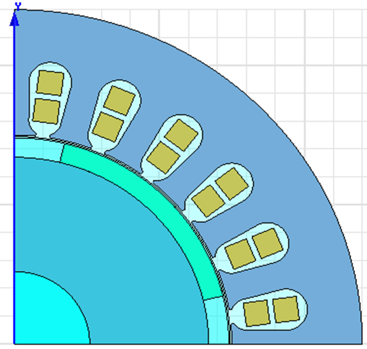
Figure 1. Finite element model of permanent magnet synchronous motor.
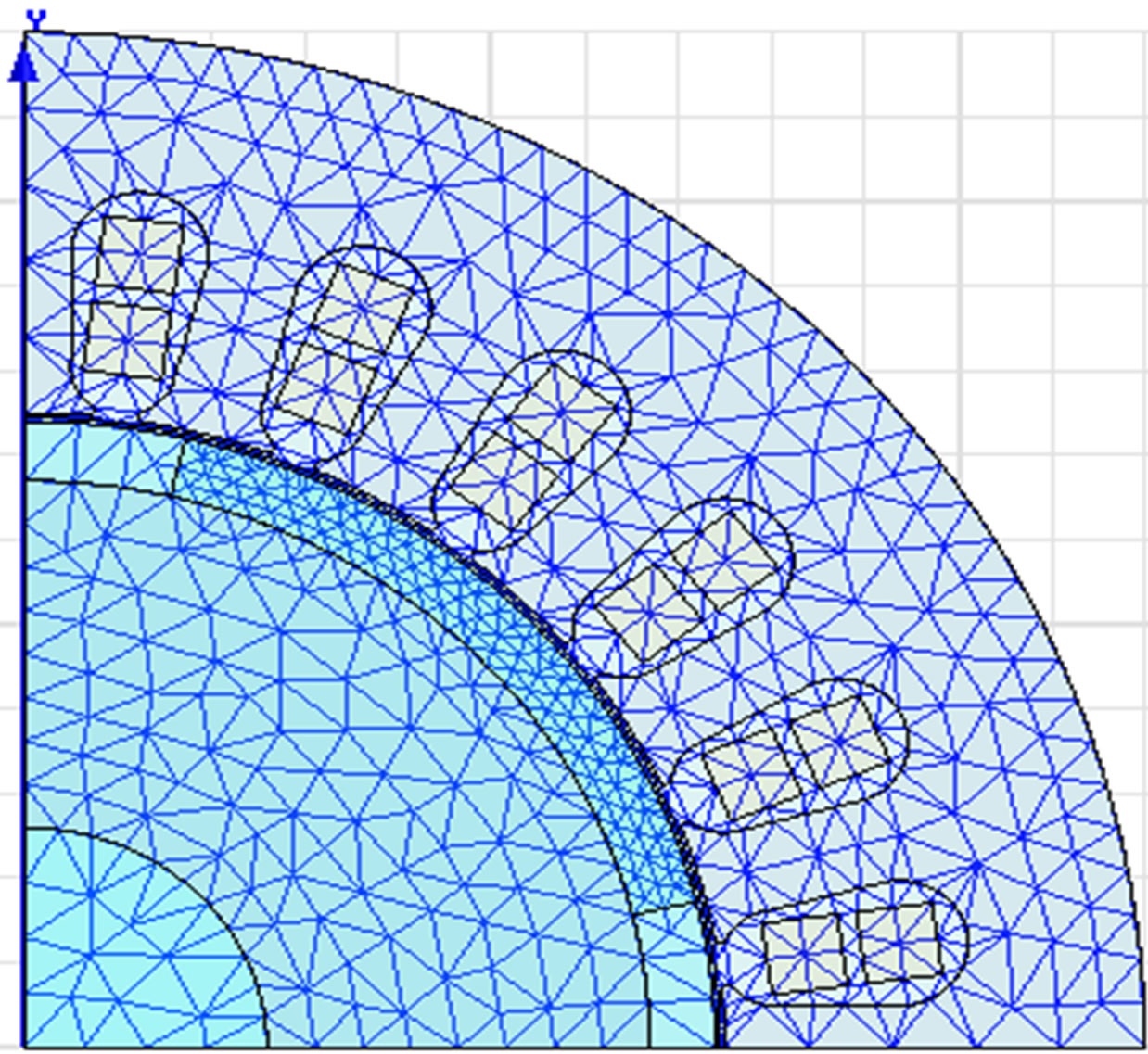
Figure 2. Mesh plots of the PMSM.
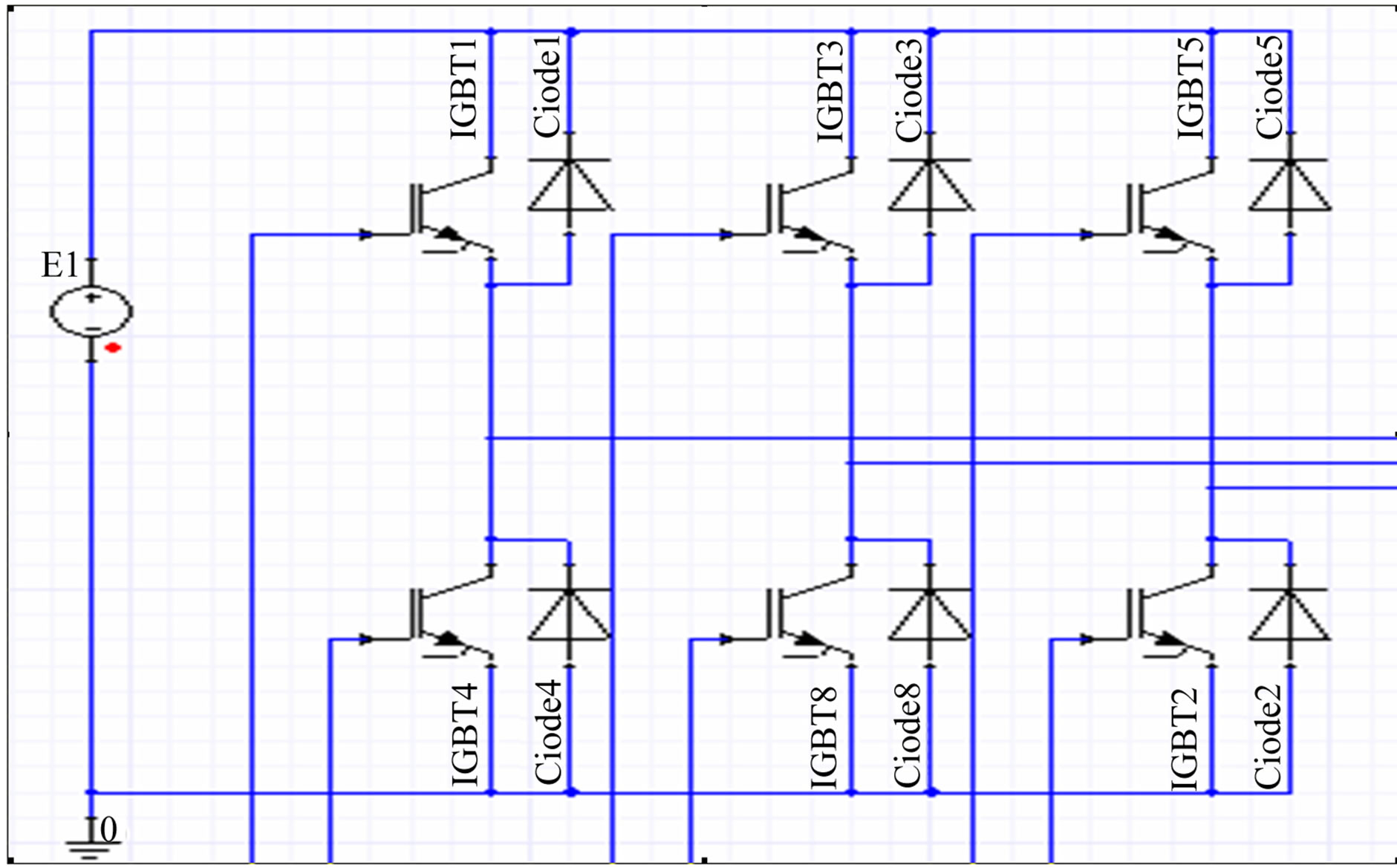
Figure 3. SPWM main circuit.
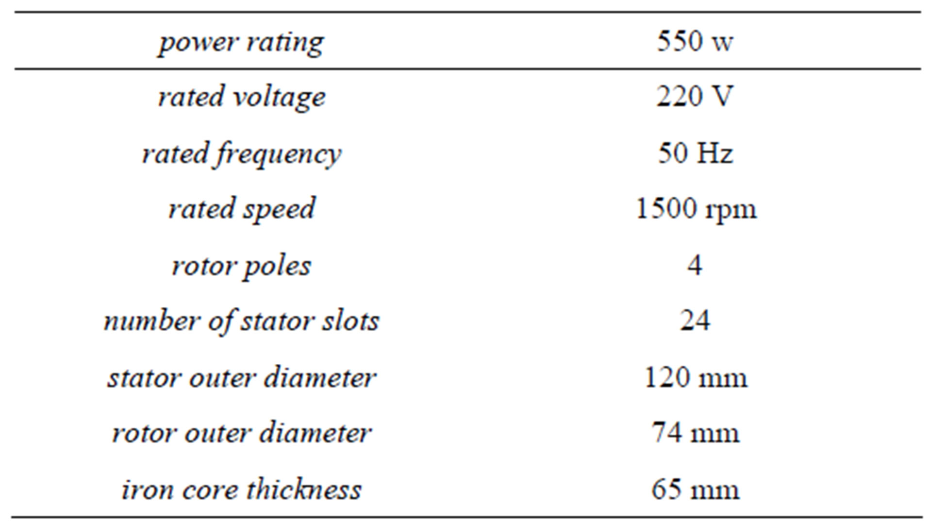
Table 1. Parameter of the selected PMSM.
The SPWM external circuit is connected. Sine wave is selected as the modulation wave. Triangle wave is selected as the carrier wave. There are the crossover points between the modulation wave and carrier wave. The time of those points decides on-off’s time of the inverter switches. The pluses with same amplitude and varying widths are produced [4]. Next several points should be concerned in the establishment of the external circuit.
1) There is a phase difference of 120 degrees between two phases in modulation wave interaction. The initial phase angle should be appropriate. The match between the fundamental wave phase angle and the motor ones can be ensured during inverting.
2) The ratio of the carrier wave frequency to the modulation wave frequency should be odd and integer times of 3. The even harmonics can be eliminated. The positive and the negative half-cycle waveform are symmetrical. The three-phase output waveform are strictly symmetrical too.
3) The fundamental wave amplitude and the modulation degree are proportional. The DC side voltage should be adjustable based on the modulation degree.
4) 2D FEM cannot take into account the effect of endwinding leakage inductance. It must be considered in connecting external circuit or the motor model [5]. SPWM drive circuit is shown in Figure 4.
The finite element model of the motor is input into the external circuit software [6]. The whole system simulation model is shown in Figure 5.
After excitations and simulation parameters of the model are set, co-simulation is carried out. The relevant data can be obtained. Phase current waveform is shown in Figure 6.
It can be seen from Figure 6 that harmonics are produced during the process of inversion. The voltage applied to the motor is not ideal sine wave excitation. Therefore there are various harmonic currents in the stator winding and the current waveform is distorted.
3. Current Harmonic Analysis
Single carrier wave signal is used in the inversion process. The output phase voltage of three-phase SPWM inverter circuit contains harmonic voltages with angular frequencies of:
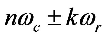 (1)
(1)
where ωc is the carrier wave angular frequency, ωr is the angular frequency for the modulation wave [7].
 (2)
(2)
In this study fc is set at 4050 Hz and fr is 50 Hz. As the
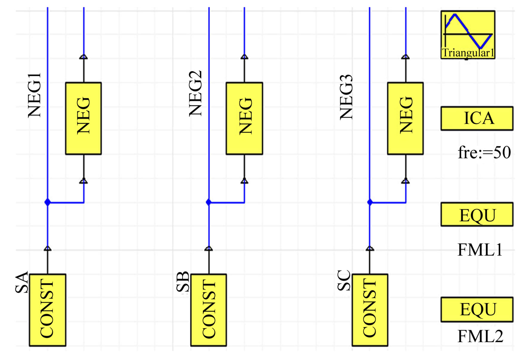
Figure 4. SPWM drive circuit.
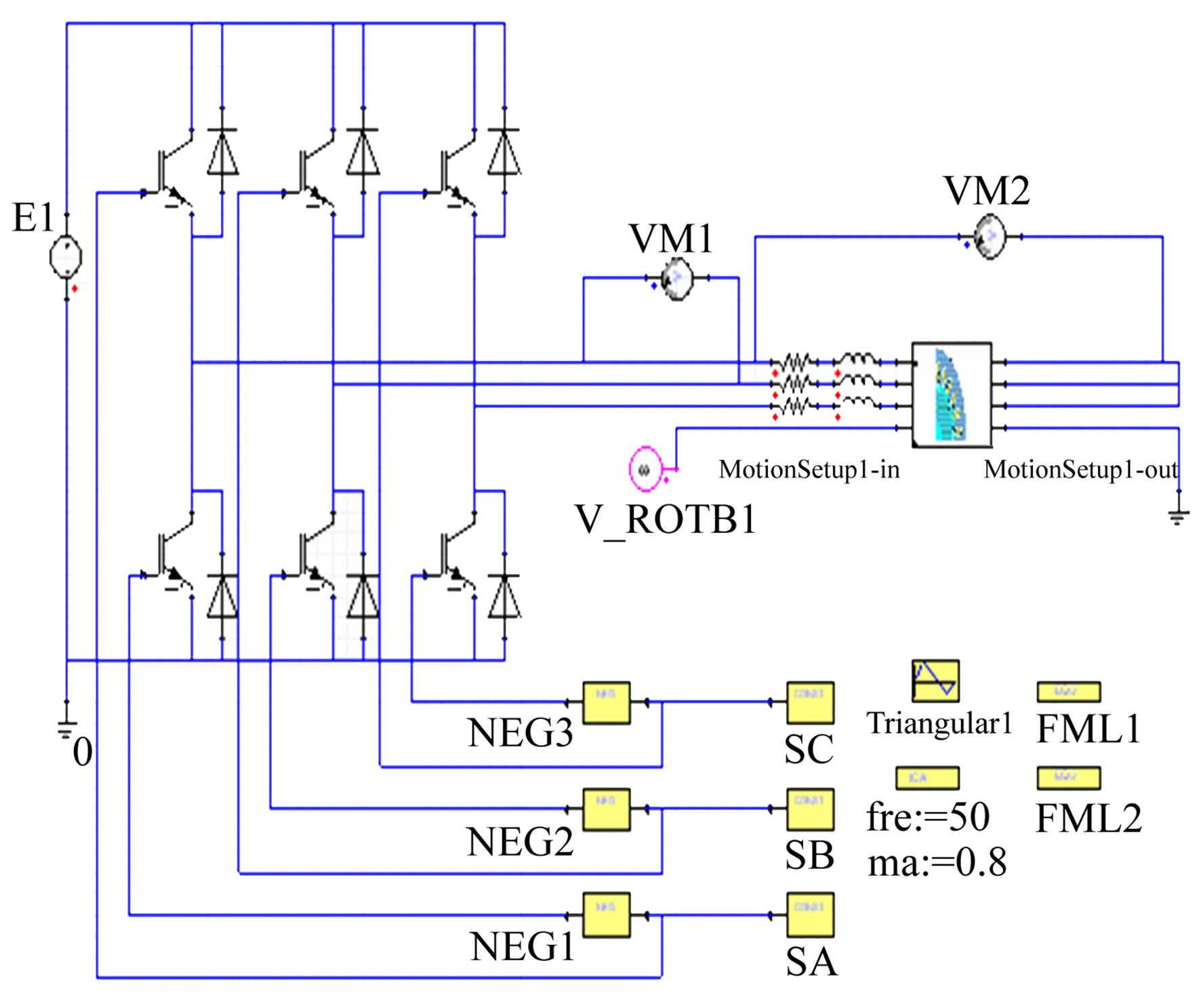
Figure 5. Co-simulation model.
carrier wave frequency is much higher than the modulation wave ones, harmonic voltages distribute at high frequencies around nfc [8]. The harmonic currents with the same frequency in the motor phase winding are produced due to harmonic phase voltage.
Fourier decomposition of the phase current is applied to get amplitudes and phase angles of harmonic currents. Harmonic spectrum is shown in Figure 7.
It can be seen from the harmonic spectrum that the harmonic currents are distributed in the vicinity of 0 Hz, 4050 Hz, 8100 Hz, 12150 Hz, mainly around 0 Hz. Higher harmonics can be easily filtered. The harmonic currents which have primary impact on the motor are mainly around 0 Hz.
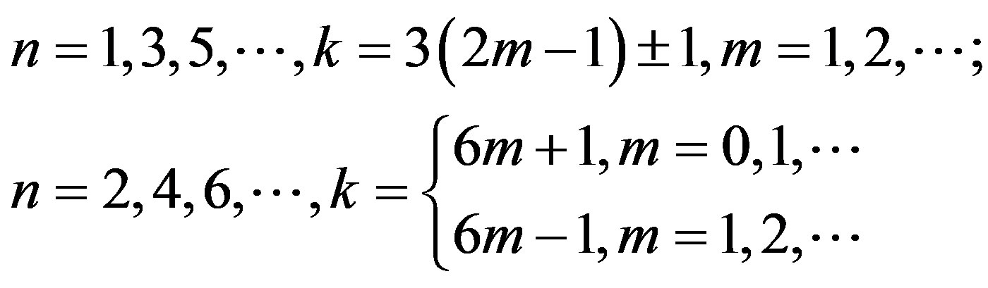
No even harmonic current exist in the stator winding of PMSM. There is a phase difference of 120n degree between two phases of harmonic currents with the same frequency in PMSM, as follows:
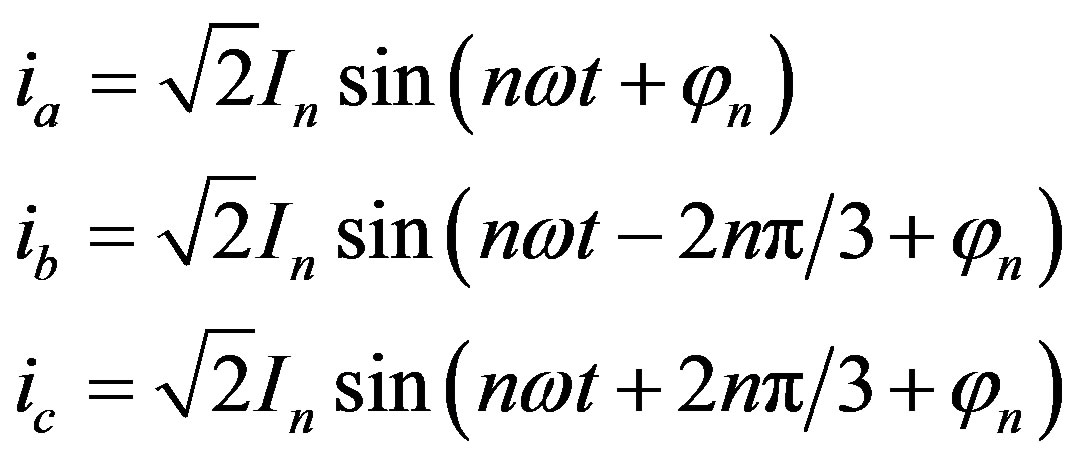 (3)
(3)
Because star connection is used in PMSM, there is not a loop for the 3rd, 9th currents. The 3rd, 9th harmonic currents do not exist in PMSM [9]. The harmonic currents impacting motors are mainly the 5th, 7th harmonic currents. The impact of the 5th, 7th harmonic currents on the motor torque are analyzed below [10].
4. The Effect of Harmonic Current on Motor Torque
The current in stator winding can be expressed as the form below:
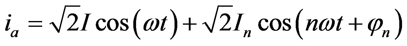 (4)
(4)
The effect of the amplitude and φ of the 5th and 7th harmonic currents on motor torque are discussed. The effect of harmonic currents on the PMSM torque in rated condition are analyzed below.
The amplitude of harmonic currents normally account for 1% - 15% of the fundamental current amplitude when the motor is energized with inverter. The amplitude of low time harmonics increase with the frequency decrease of inverter.
It can be got that the amplitude of fundamental current is 2.25 A. The 5th harmonic current is loaded with 0 A, 0.05 A, 0.1 A, 0.15 A, 0.2 A for simulation. The 7th harmonic current is loaded with 0 A, 0.05 A, 0.1 A, 0.15 A, 0.2 A too. The changing trend curves of torque ripple with increase of the 5th and 7th harmonic currents is shown in Figure 8.
It can be found that the range of torque ripple is 1.5466 N·m when fundamental current is loaded only. The range of torque ripple is increased by harmonic currents. The range of torque ripple gets larger as the amplitude of the 5th or 7th harmonic currents increases. It is against the steady operation of the motor.
The amplitude of harmonic currents has little effect on the average torque of PMSM. The changing trend of average torque as the 5th and 7th harmonic currents increase is shown in Table 2.
Besides the amplitude of harmonic current which have effect on the motor torque, the φ in expression (4) will also have effect on the motor torque [11]. To analyses quantitatively the effect of different φ, the 5th (7th) harmonic current in stator winding is assumed 0.1 A. The harmonic current is loaded with fundamental current of 2.25 A together. The interval of φ is of 30˚. The changing trend of torque ripple as φ is shown in Figure 9.
The torque ripple caused by the 5th and 7th harmonic currents both goes up and down twice in a cycle of φ. The motor has a small torque ripple when φ is around 0˚ and 180˚. The motor has a big torque ripple when φ is around 90˚ and 270˚.
The average torque of PMSM in different φ can be got too.
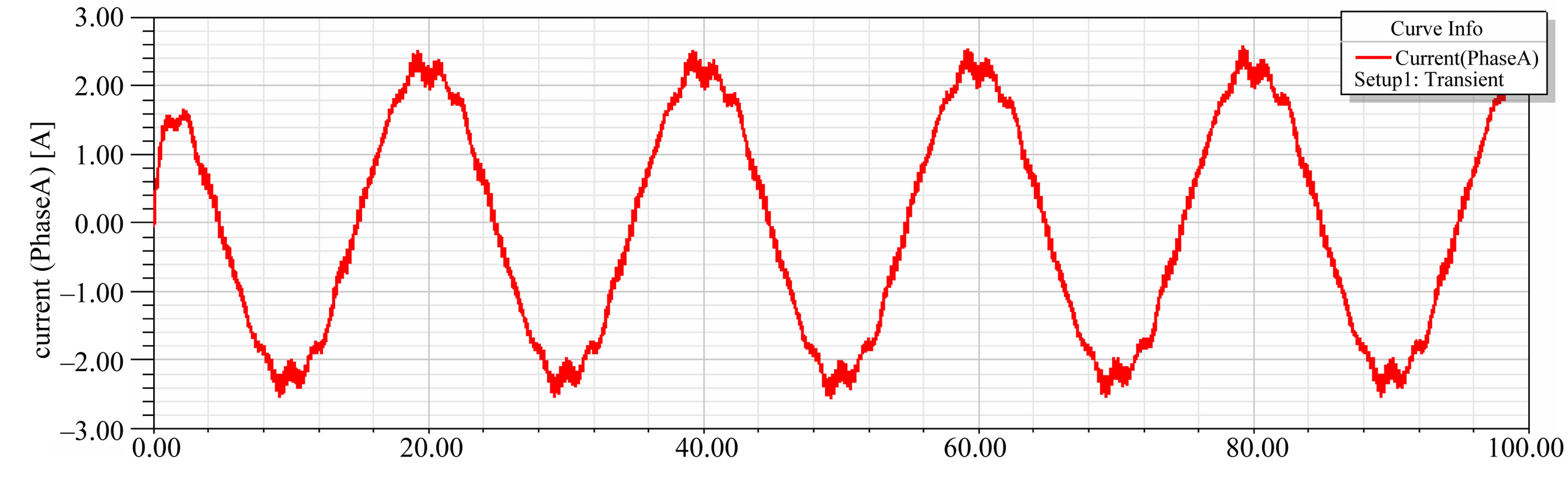
Figure 6. Phase current waveform.
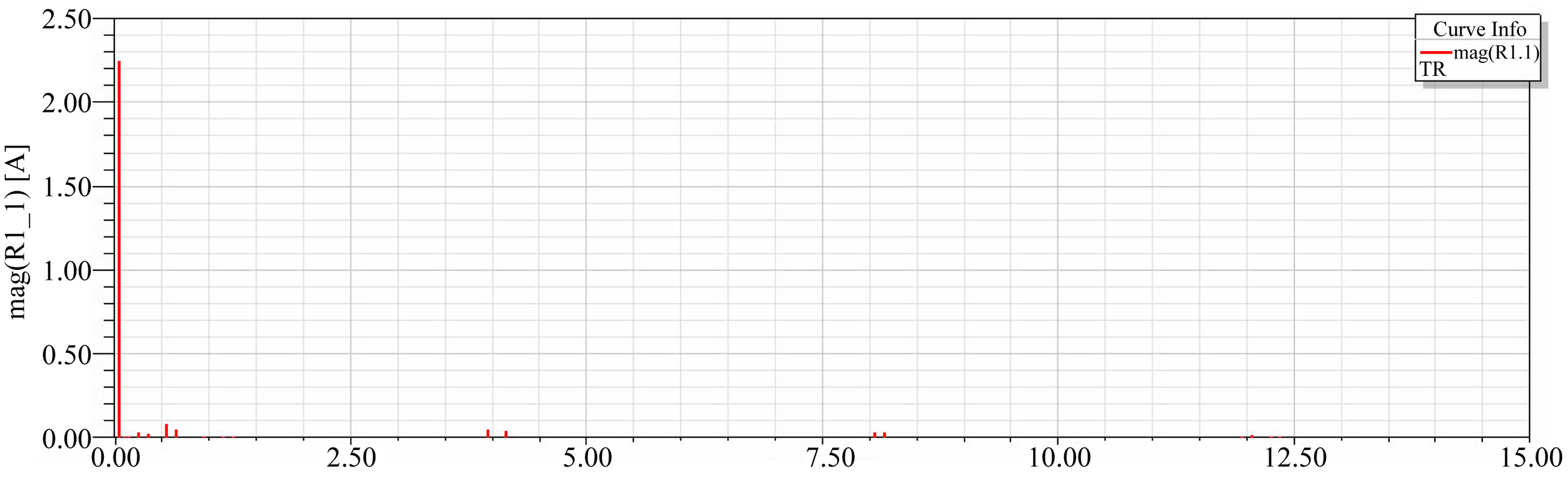
Figure 7. Harmonic current spectrum.
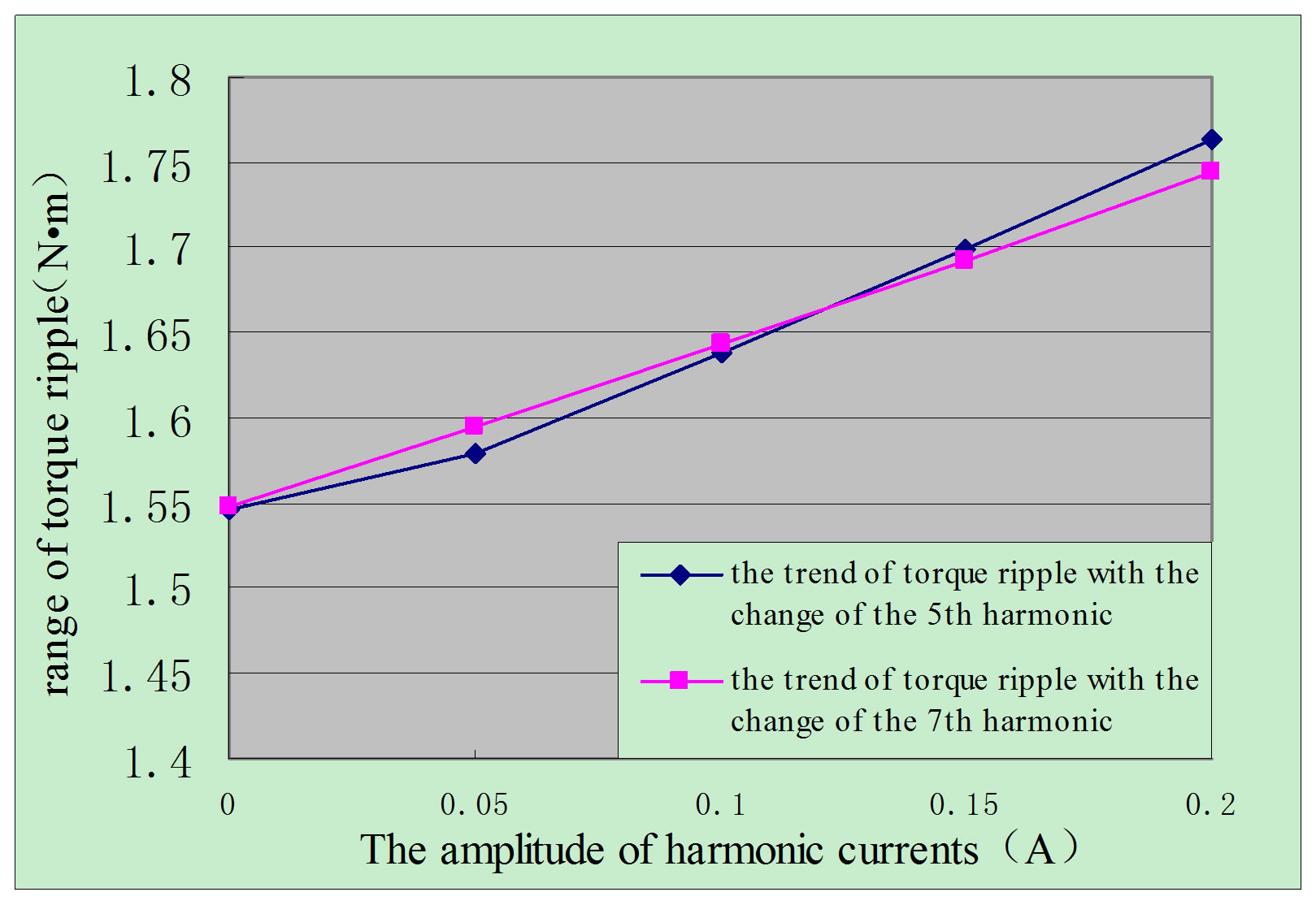
Figure 8. Changing trend of the range of torque ripple as the 5th and 7th harmonic currents increase.
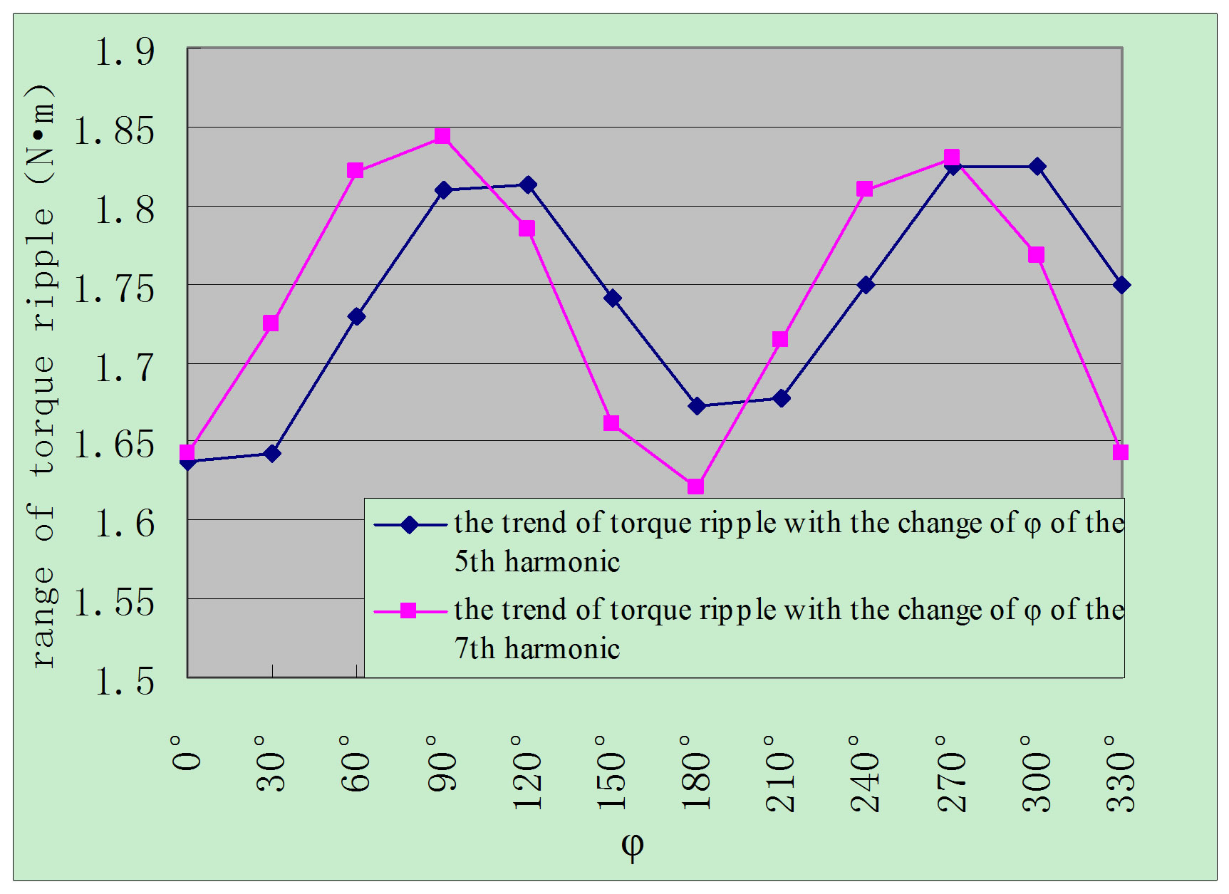
Figure 9. Changing trend of the range of torque ripple as the value of φ increases.
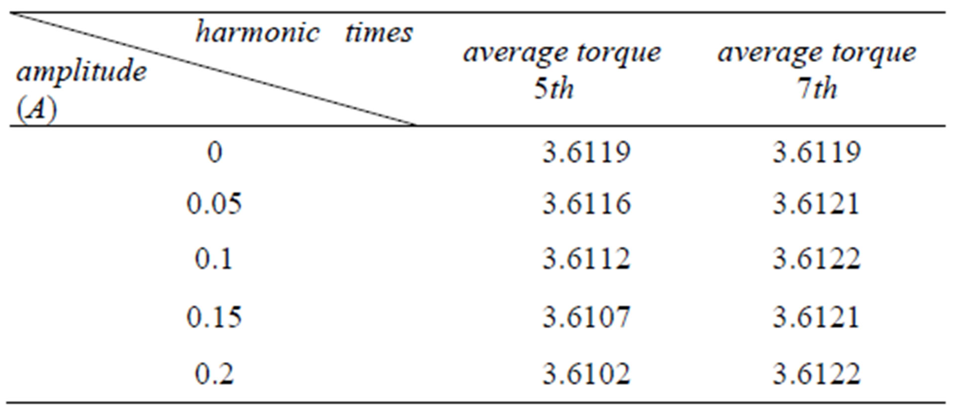
Table 2. The average torque of PMSM with different amplitude of harmonic currents (N·m).
The change of φ of harmonic currents has visibly little effect on the motor average torque. The average torque is hardly changed by φ. And Table 3 lists the average torque of PMSM with different φ.
Data such as amplitude and phase angle of these harmonic currents in rated condition can be got from the simulation and harmonic analysis above. It is known that the amplitude of fundamental wave current is 2.25 A. The amplitudes of 5th and 7th harmonic current are 0.04 A and 0.03 A. Fundamental wave and the 5th, 7th harmonic currents in rated condition can be loaded using finite element software as excitation.
When fundamental wave and the 5th, 7th harmonic currents are being loaded in winding, it is important how to set the initial phase angles of current excitations correctly. Otherwise, torque curves will get wrong. The initial phase angle of current excitation should be the difference between power factor angle and initial phase
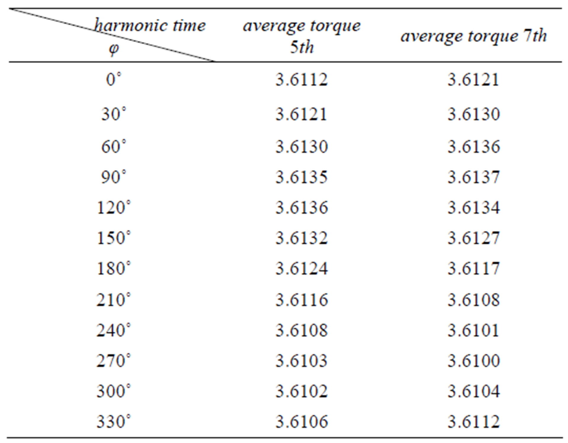
Table 3. The average torque of PMSM with different φ (N·m).
angle of voltage excitation. The method below is used to determine the initial phase angle of current excitation. Take the fundamental wave current for example.
The initial phase angle of voltage excitation is φ1. When the motor works in steady state, the phase angle of current at the integer multiple time of cycle is φ2. The phase angle of voltage at that time is φ1. φ1 – φ2 is the power factor angle. It can be drawn that initial phase an gle of current excitation is φ1 – (φ1 – φ2). The value is φ2. The phase angles of these harmonic currents at the integer multiple time of cycle obtained by harmonic analysis are the initial phase angle of current excitations.
When the fundamental current of 50 Hz is loaded only the torque curve is shown in Figure 10. It would be convenient to compare the torque curve with ones at the cases of harmonic currents being loaded.
When fundamental current is loaded, average torque of the motor is 3.6119 N·m. The range of torque ripple is 1.5466 N·m.
When the fundamental current and 5th harmonic current are loaded together the torque curve is shown in Figure 11.
In this case average torque of the motor is 3.6172 N·m. The range of torque ripple is 1.6569 N·m. It can be found that the 5th harmonic current has little effect on the motor average torque. But it causes a big change of torque ripple.
When the fundamental current and 7th harmonic current are loaded together the torque curve is shown in Figure 12.
The average torque of the motor is 3.6174 N·m. The range of torque ripple is 1.6183 N·m. It can be found that the 7th harmonic current has little effect on the motor
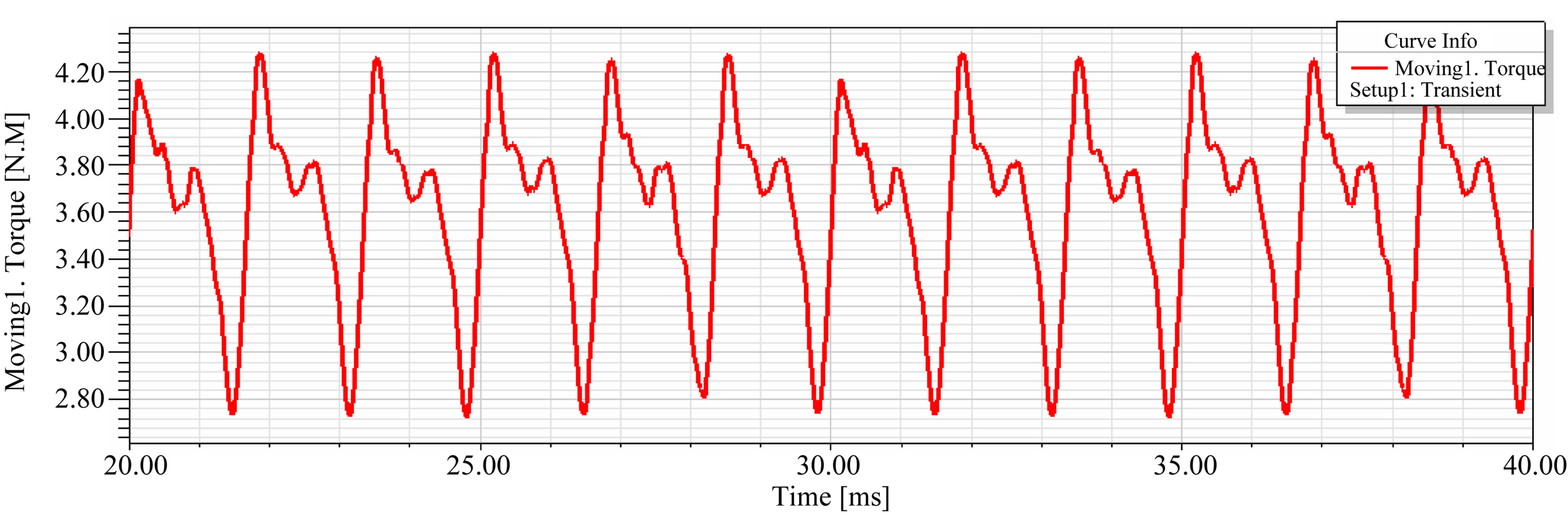
Figure 10. Torque curve when fundamental current is loaded only.
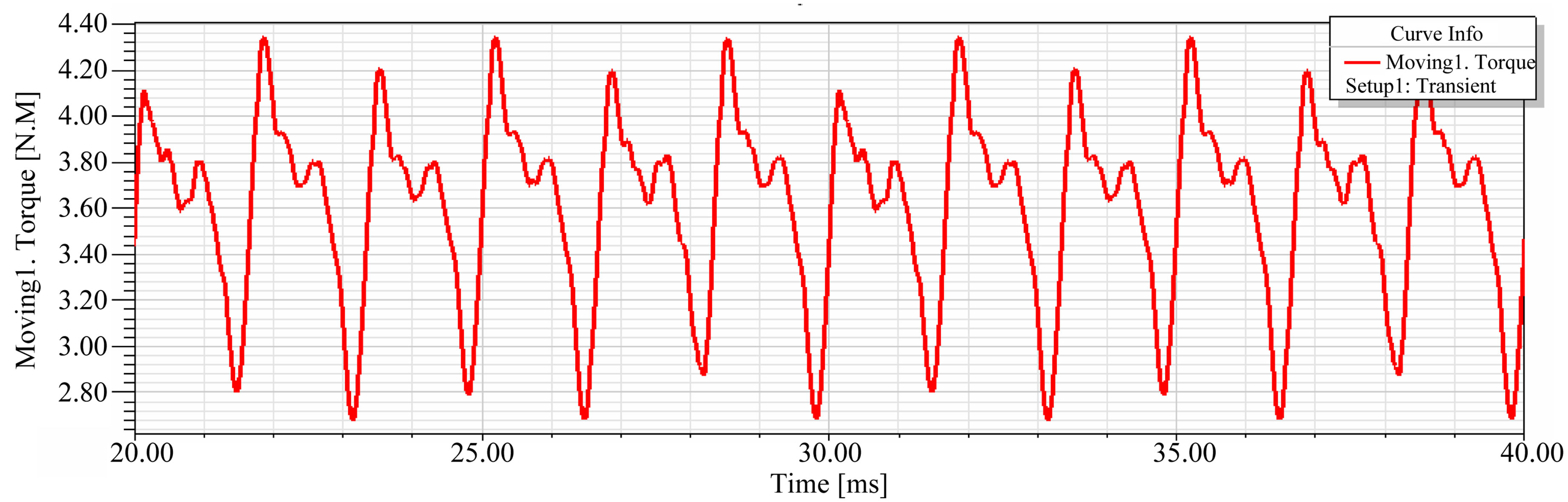
Figure 11. Torque curve when the fundamental current and 5th harmonic current is loaded.
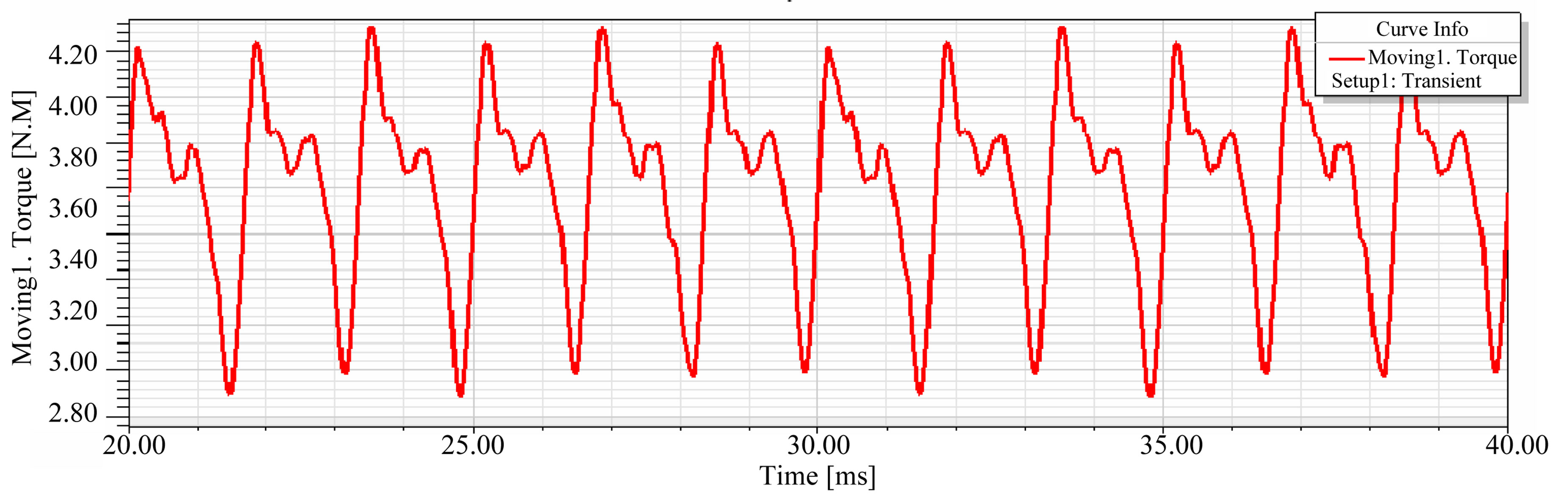
Figure 12. Torque curve when the fundamental current and 7th harmonic current is loaded.
average torque. But it causes an increase on torque ripple.
From the analysis above, it is indicated that the amplitude of the 5th harmonic current is higher than that of the 7th in rated condition of the PMSM. Harmonic currents can increase the range of torque ripple. Harmonic currents have little effect on the average torque.
5. Conclusion
The low harmonic currents are mainly the 5th and 7th harmonic currents in the PMSM driven by inverter. All these harmonic currents have an effect on the torque of PMSM. The expansion of torque ripple can be caused. The torque ripple gets larger as the amplitude of harmonic current gets larger. The range of torque ripple also changes as φ of harmonic current changes. The harmonic currents have little effect on the motor average torque. The conclusion can be drawn that harmonic currents mainly affect the range of torque ripple of PMSM.
REFERENCES
- H. X. Wei, “Harmonic Analysis and Simulation of Induction Motor Fed by SPWM Inverter,” Master’s Thesis, Harbin University of Science and Technology, Harbin, 2004.
- Z. A. Wang and J. Huang, “Power Electronic Technology,” 4th Edition, China Machine Press, Beijing, 2000.
- S. P. Yang, “The Theory and Application Research of Harmonic-Suppression of VVVF,” Master’s Thesis, University of Electronic Science and Technology of China, Chengdu, 2000.
- Z. Wang, “Study on PMSM Design and Air Gap Magnetic Field Optimizing Design,” Master’s Thesis, Haerbin Institute of Technology, Haerbin, 2006.
- J. H. Zhu, “Effect of Rotor Eccentricity on the Performance and Protection of the Large Salient-Pole Synchronous Generator,” Master’s Thesis, Tsinghua University, Beijing, 2007.
- S. L. Zhu and Q. J. Wang, “Modeling and Simulation of Permanent Magnet Synchronous Generator Based on Ansoft,” Electrical Machinery Technology, Vol. 4, 2008, pp. 2-3.
- P. Zuniga-Haro and J. M. Ramirez, “Modeling of MultiPulse VSC Based SSSC and STATCOM,” Journal of Electromagnetic Analysis and Applications, Vol. 2, No. 3, 2010, pp. 146-147. doi:10.4236/jemaa.2010.23022
- H. Mikami and K. Ide, “Dynamic Harmonic Field Analysis of an Inverter-Fed Induction Motor for Estimating Harmonic Secondary Current and Electromagnetic Force,” IEEE Transactions on Energy Conversion, Vol. 14, No. 3, 1999, pp. 466-468. doi:10.1109/60.790898
- H. E. Mazin and J. Gallant, “A Probabilistic Analysis on the Harmonic Cancellation Characteristics of the Scott Transformer,” Journal of Electromagnetic Analysis and Applications, Vol. 2, No. 1, 2010, pp. 20-21. doi:10.4236/jemaa.2010.21003
- T. M. Jahns and W. L. Soong, “Pulsating Torque Minimization Techniques for Permanent Magnet AC Motor Drives,” IEEE Transactions on Industrial Electronics, Vol. 43, No. 2, 1996, pp. 323-325. doi:10.1109/41.491356
- E. R. Collins, J. R. Shirley and J. C. Fox, “An Experimental Investigation of Third Harmonic Current Distortion in Single-Phase Induction Motors,” 13th International Conference on Harmonics and Quality of Power, Wollongong, September 2008, pp. 1-7.