Journal of Electromagnetic Analysis and Applications
Vol. 3 No. 10 (2011) , Article ID: 8143 , 6 pages DOI:10.4236/jemaa.2011.310064
Planar Inverted-F Antenna (PIFA) Design Dissection for Cellular Communication Application
![]()
1Amirkabir University of Technology, Electrical Engineering, Tehran, Iran; 2Amirkabir University of Technology, Electrical Engineering, Tehran, Iran.
Email: n.firoozy@aut.ac.ir
Received July 10th, 2011; revised August 11th, 2011; August 28th, 2011.
Keywords: U-Shaped PIFA, Miniaturization Technique, PIFA Design Block Diagram, Periodic Grooves, SAR
ABSTRACT
An in-depth approach towards the design of PIFA has been taken. After discussing the essential parameters involved in the design procedure and introduction of a design algorithm, a miniaturized dual-band PIFA is introduced. Different specifications of the proposed antenna are measured both through computer simulation and fabricated PIFA. Also, the Specific Absorption Rate (SAR) is introduced and measured for this antenna.
1. Introduction
Since the cellular communication revolution, realizing an antenna that meets the needs of mobile phone users has been a challenge. Monopole λ/2 antennas were the first answers to this demand which soon gave place to PIFAs. Monopole disadvantages like the antenna’s venerability to physical damage, uncontrolled radiation toward user and disability to resonance at multi-frequencies on one hand and advantages of PIFA naming a desired crosspolarization, easy feeding, low SAR and inside-handset fabrication was the reason of such transmission [1,2].
Unfortunately, many researches have recently focused only to obtain the specified features of PIFAs when designing, using computer simulators solely through error and try and without paying enough attention on what actually happens through their design. In this report, it has been tried to cover this problem.
In brief, PIFAs are conducting plates called radiating patches that are parallel to a ground and are connected to ground by a plate making it able to resonance at λ/4 [3].
It is necessary to mention that the size of PIFA is of critical importance since the need to more compact handsets is felt more than ever. A rule of thumb in PIFA design is that any method to reduce the amount of resonance frequency can be manipulated the other way round to reduce the antenna size while keeping resonances untouched. Ways through which this goal is realized are called miniaturization techniques.
2. Design Procedure
In recent years, the use of GSM1800 instead of GSM800 is gaining more and more popularity in some countries. Also, for most handsets, Bluetooth application is becoming a have to. Since the operating frequencies of these two are rather close and they do not belong to the same harmonic resonance group, a different antenna is usually used for Bluetooth communication.
Here, a dual-band PIFA has been chosen which is to satisfy the requirements mentioned in Table 1 .
Also, the U-Shaped PIFA structure has been chosen due to its minimum guided radiation towards the user end at the second resonance frequency compared to some other designs [4].
2.1. Resonate Frequencies
It is fundamental to understand the way we can obtain resonances in PIFA. The author found the equivalent circuit presentation the best way to gain such understanding. The schematic in Figure 1 shows how the patch is represented by two parallel RLC circuits and the coaxial feed line is modeled by an inductor, L3. Using such robust method, many complex miniaturization techniques are easily understood. Consequently, modes propagate at TM01, TM10, TM02, TM11 and so on for higher resonances,
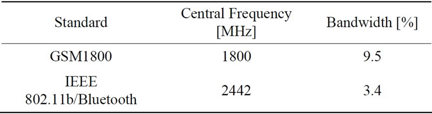
Table 1. IEEE Standards for cellular communications.
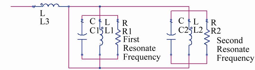
Figure 1. The equivalent circuit of a dual-band PIFA.
each belonging to one parallel RLC [5]. These parallel RLCs can be achieved by designing different electrical paths each equal to a related resonance frequency of a λ/4.
A typical U-shaped patch is shown in Figure 2. The resonance frequencies are approximated by Equation (1) which is related to the electrical lengths.  is the relative permeability of the medium in between the ground and radiating patch. Also, H is the height of the patch in reference to the ground.
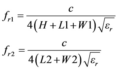 (1)
(1)
We may also notice other resonance frequencies. Some of these are main resonance harmonics and the others are caused by our limited-size ground which is fed through the short pin proxy.
2.2. Bandwidth
Since PIFA has an intrinsic small bandwidth, many ways has been introduced to increase it so far. Using a pin instead of a plate to short the radiating patch can effectively improve the bandwidth which is critical in cellular communications [6]. Also introducing slots through a defected ground is a popular way to achieve such goal. These slots would resonance at same frequencies and therefore may increase the bandwidth.
According to Fano integrals, the maximum bandwidth of a microstrip antenna is limited by its volume and the equivalent matching time constant [7]. So we have to bear in mind that by introducing slots, we are actually increasing the electrical volume of our radiating patch and also losing the isotropic pattern, maximum gain, efficiency or a combination of these all, in a range of frequencies.

Figure 2. The U-shaped Patch primitive schematic.
A second way would be by adjusting the space in between the feed and short. Different simulations proved to the author that by feeding at the middle and shorting at the patch end, best bandwidth is achieved in most cases.
The Q factor of PIFA is reversely related to the bandwidth. At first look, PIFA antenna is simply a capacitor with shorted plates so anything that lowers the capacitance and so the Q factor should result in bigger BW. So third way would be choosing an optimum, not a maximum, height for our radiating patch. This can be explained by noting that in the equivalent circuit, the coaxial feed is presented by an inductor which is increased at bigger heights. We should also remember that PIFA is supposed to be placed inside a handset so there is a limit on the achievable patch height. In a similar way, choosing a higher than one  is also recommended in some reports since it increases the capacitance. But since it means higher losses and so a distorted return-loss and reduced efficiency, the author does not support such a choice. Also, capacitive loading is reported to be implemented to decrease the coaxial inductor [8]. One downside to this choice would be its contradiction to idea of miniaturizing the patch and also difficulties in mass manufacturing.
Ground plate size in both length and width is also influential in bandwidth. Since we have a limited space inside the handset we can not accept an infinite ground assumption. This factor must be optimized mostly through simulation and with having the size of available PCB ground in handsets in mind. Same rule applies for the placement coordinates of the radiating patch over the ground.
2.3. Periodic Grooves
Periodic grooves are new methods to lower the resonance frequencies without badly affecting other PIFA parameters. This reduction depends on the number of groves and works through the increase of electrical length of PIFA at a specific resonance frequency. In Figure 3, the concentration of fields at the groove edges are apparent.
As observed in Figure 4, the importance of the grooves is that when two resonance frequencies are too

Figure 3. Electrical Field magnitude comparison between a patch without and with grooves respectively.
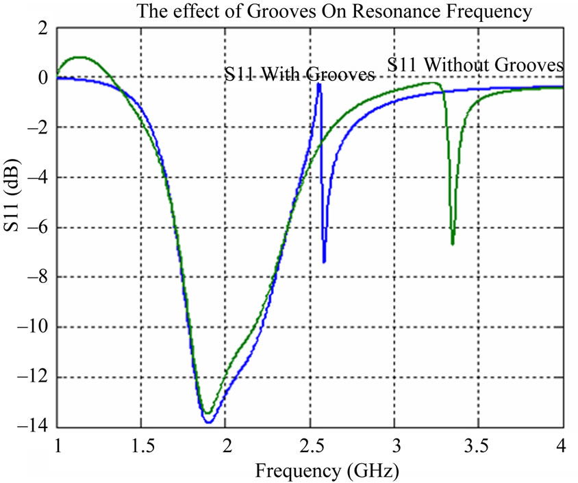
close together so other methods can not realize the required resonances, like this U-shaped example since the gap between resonating parts is limited, grooves are found extremely effective.
2.4. SAR Definition
The electromagnetic fields caused by currents on antenna surface and edges, propagates where the head and hand of user is near by. As a result, cell polarization in human body happens due to heat induced in close body parts. Such exposure, if not controlled, can damage user’s health. This power absorbed by user is measured by a parameter called Specific Absorption Rate, SAR, and is defined as below:
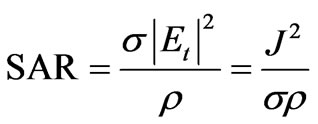 (2)
(2)
At which point SAR is in (W/Kg). Also σ is the conductivity and ρ is the mass density,  is the total amplitude of electrical field in root mean square. An average integral is used locally over a mass block to transfer from point SAR to average SAR.
Countries and organizations have declared standards for the maximum SAR allowed produced by antennas used in handsets [9]. Some of these values are listed in Table 2.
A number of techniques including a clever placement of the PIFA in handset or using an L-shaped ground are introduced in some reports [10]. In all these, we have to consider the mass manufacturing drawbacks and then decide whether using them or not. Also, the isotropic radiation pattern should remain untouched as much possible.
2.5. Design Block Diagram
We first start by achieving a rough design through theory and simulation simultaneously. If we are satisfied by what we gained, we go to a final fine tuning step. But if not, we used the miniaturization techniques explained above. We should not forget that in most cases, the antenna size is fixed or has an upper size band limit. Also, making it more compact will usually cost us in other areas. So, if we have a rather fixed size antenna, we go to the compensation step.
It is necessary to remember that whatever technique we use to gain a better impedance match at the feed point, will result in a sharper return-loss at resonance frequencies. Consequently, our bandwidth will be reduced. On the other hand, there is a relation between antenna size and resonance frequencies. At compensate step, we should come up with a trade-off between all these. If the results of this step are close to what we want, we go straight to the final tuning. If not, miniaturization techniques should be applied once more. Steps are shown in Figure 5.
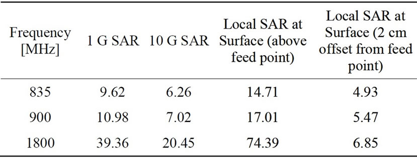
Table 2. IEEE Standards for cellular communications SAR.
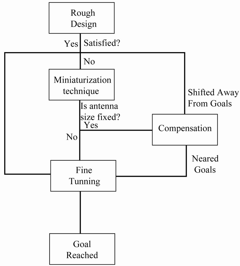
Figure 5. Design block diagram.
2.6. Design
Based on techniques explained above, following PIFA was designed with specification mentioned in Table 3. An schematic of simulated PIFA is presented in Figure 6.
The lithography process forces us to choose a substrate for physical support. Therefore by placing the patch in a position which faces the ground directly by its conductor part, it has been effectively proven by simulations that the unwanted effects of such substrates are minimized.
A single groove was sufficient enough for achievement of the second desire resonance frequency and the height at which maximum bandwidth is realized found to be 6 millimeters.
The ground size is significantly smaller than similar conventional PIFAs and this advantage provides us with a much bigger space for other electronic handset parts to be implemented in cell phones. The fabricated antenna is pictured in Figure 7.
3. Measurements
3.1. Return-Loss and Pattern
The return-loss has been measured both through computer simulation and also after fabrication, through a network analyzer. A good agreement between both results has been observed. Network Analyzer was well adjusted for small antenna measurements and the environment around the PIFA was as much free of reflector as needed so that the results would be reliable. Measurements are shown in Figure 8 in comparison to simulated results.

Table 3. Physical dimensions of the proposed PIFA (All in milimeter).

Figure 6. Designed PIFA schematic.

Figure 7. Fabricated designed PIFA before and after assembly.
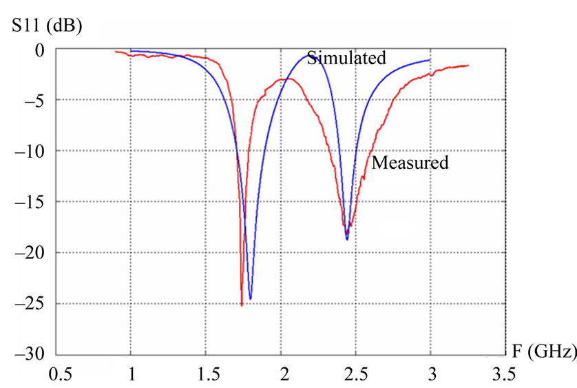
The small shift in between measured results by computer simulator and Network analyzer is caused by the cable losses, inexact relative permeability of substrate and also PIFA manufacturing imprecision.
The total electrical field pattern is also demonstrated in Figure 9 for both frequencies in dB.
3.2. SAR Calculation
Setup in Figure 9 was used to calculate SAR. Pease take notice of the way cell phone is placed. It is assumed that the cell phone would be a folded one and the antenna will be placed in the lower side so that minimum radiation would be present at near ear area. Results are shown in Figure 10.
As seen in presentations at Figure 10, we can conclude make the comparison in Table 4 according to [9].
And so, the SAR is within the limited amounts. Although by paying attention to the spread of heat in Figure 10, we notice that these maximum amounts only happen at very limited points and in total, the average SAR on hand and head surface is much less than these maximum numbers. Also, the placement of antenna inside a handset case will reduce the electromagnetic field effect dramatically. In other words, SAR calculation above, was the worst case scenario and yet we could stay within the standards.
4. PIFA Placement in Near Head and Hand Position
It is useful to have a final check on how the dielectric
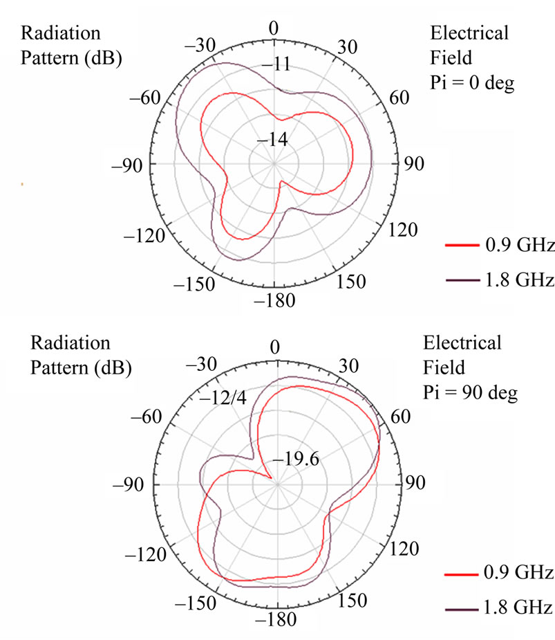
Figure 9. E total in dB for both resonance frequencies.
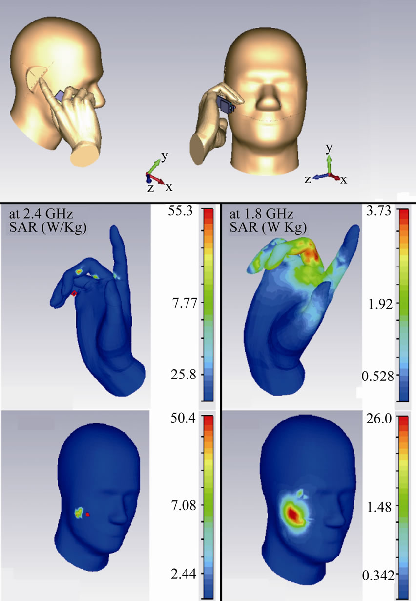
Figure 10. SAR setup and measured SAR on head and hand.
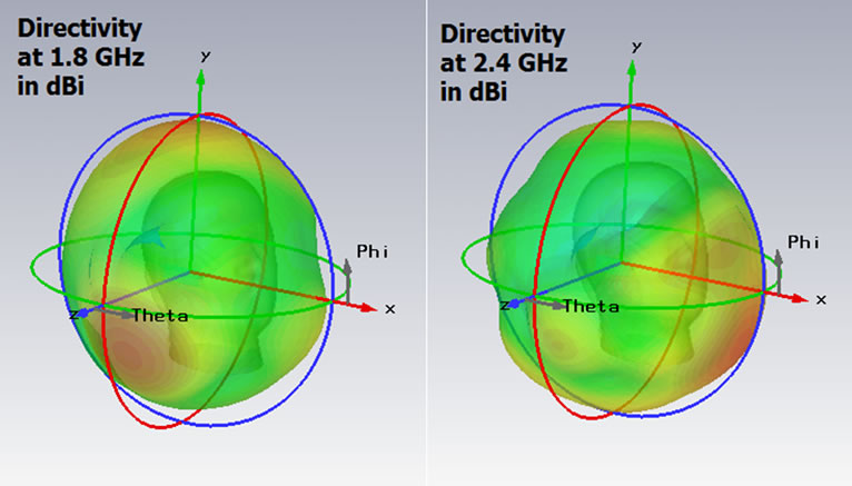
Figure 11. Directivity for both resonance frequencies (3D directivity pattern has been magnified for better presentation).
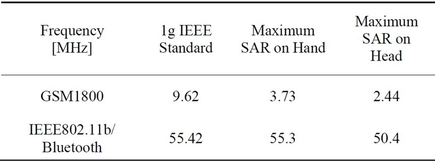
Table 4. Comparison between measured and standard SAR.
hand and head as body parts may affect the directivity of the designed antenna. Figure 11 shows such setup. As we see, the isotropic pattern is still well preserved. Also, we can see that through an excellent choice of direction placement for antenna, the maximum directivity is not directed towards the head but between the narrow space in between head and hand while using the handset.
5. Final Note
Computer simulators used are HFSS10 Ansoft for return-loss and pattern calculation and CST for SAR simulation. Also Phantom model is used for the latter purpose. Diagrams are also plotted by MATLAB given the data measured both in simulation and by Network Analyzer in some cases.
6. Acknowledgements
The author gratefully acknowledges the assistance of the Microwave and Antenna laboratories of University of Tehran.
REFERENCES
- J. Fuhl, P. Nowak and E. Bonek, “Improved Internal Antenna for Hand-Held Terminals,” Electronics Letters, Vol. 30, No. 22, 1994, pp. 1816-1818. doi:10.1049/el:19941258
- A. M. M. Owag, “Multiband Antenna for GSM and 3G Mobile System,” University Technology Malaysia, Johor, 2006.
- K. Fujimoto, A. Henderson, K. Hirasawa and J. R. James, “Small Antennas,” Research Study Press, Hertfordshire, 1987.
- K. L. Wong, “Planar Antennas for Wireless Communications,” John Wiley & Sons, Hoboken, 2003.
- A. Ghorbani, M. Ansarizadeh and R. A. Abd-alhameed, “Bandwidth Limitations on Linearly Polarized Microstrip Antennas,” IEEE Transactions on Antennas and Propagation, Vol. 58, No. 2, 2010, pp. 250-257. doi:10.1109/TAP.2009.2037768
- K. L. Wong, “Compact and Broadband Microstrip Antennas,” John Wiley & Sons, Hoboken, 2002. doi:10.1002/0471221112
- R. M. Fano, “Theoretical Limitations on the Broadband Matching of Arbitrary Impedances,” [Online]. http://dspace.mit.edu/handle/1721.1/12909
- C. R. Rowell and R. D. Murch, “A Capacitively Loaded PIFA for Compact Mobile Telephone Handsets,” IEEE Transactions on Antennas and Propagation, Vol. 45, No. 5, 1997, pp. 837-842. doi:10.1109/8.575634
- Standards at IEEE under the Code Name: IEEE P1528- 2003™ form Point One to Point Four.
- F. R. H. Siaho and K. L. Wong, “A Shorted Patch Antenna with an L-Shaped Ground Plate for Internal Mobile Handset Antenna,” Microwave and Optical Technology Letters, Vol. 33, No. 4, 2002, pp. 314-316. doi:10.1002/mop.10305