Journal of Electromagnetic Analysis and Applications
Vol. 1 No. 1 (2009) , Article ID: 190 , 4 pages DOI:10.4236/jemaa.2009.11003
Reduction of Cogging Torque in Permanent Magnet Flux-Switching Machines
1College of Electrical Engineering, Zhejiang University, Hangzhou, 310027, China, 2Department of Aerospace Power and Sensors, Defence College of Management and Technology, Cranfield University, Shrivenham SN6 8LA, United Kingdom.
Email: wangyu88207028@163.com
Received January 18th, 2009; revised February 5th, 2009; accepted February 20th, 2009.
Keywords: Permanent Magnet, Flux-Switching Machines, FEM
ABSTRACT
Permanent magnet flux-switching machine (PMFSM) is a relatively new structure. Available literatures mainly focused on its general design procedure and performance analysis. In this paper, Finite Element Method (FEM) is taken to analyze various design techniques to reduce the cogging torque in a prototype 12/10-pole PMFSM.
1. Introduction
The permanent magnet flux-switching (PMFSM) machine is a relatively new type of electric motor. It has both windings and magnets in stator and it is a combination of switched reluctance motor (SRM) and the inductor alternator [1]. Recent research has revealed that the PMFSM has the advantages of high power/torque density, high efficiency, and high flux-weakening capability. However, the available papers mainly focused on general design procedure [2,3,4,5,6], and performance analysis [7,8,9,10]. Due to the unique structure, the cogging torque in the PMFSM which results from the interaction of the stator permanent magnets with the rotor teeth is relatively high comparing with other types of PM motors, producing vibration and acoustic noise and deteriorating motor performance.
In this paper, FEM is taken to analyze various design techniques to reduce the cogging torque in a prototype 12/10-pole PMFSM.
2. Factors Influencing Cogging Torque
2.1 Motor Model
Figure 1 shows the cross-section of a 3-phase 12/10-pole PMFSM. It has 10 poles teeth on rotor which is the same as a SRM rotor, and 12 poles on stator. Each stator pole has two iron teeth with a magnet sandwiched between them. The magnets are tangentially magnetized with opposite direction in any adjacent magnets. Moreover, each stator pole is wound around with a concentrated coil, and each phase has 4 coils. Table I gives the specification of the PMFSM studied in this paper.
2.2 Cogging Torque Calculation
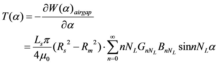
Cogging torque is due to energy variation within a motor as the rotor rotates, even if there is no current in windings. Since the energy variation in magnets and iron is negligible compared to that in air, cogging torque for a conventional inner-rotor surface-mounted PM brushless motor can be expressed as follows [11]:
 (1)
(1)
where Ls,  , Rs, Rm,
  are the stack length, air permeability, stator bore radius, magnet outer radius and rotation angle of rotor, respectively; GnNL, BnNL are the corresponding Fourier coefficients of relative airgap permeance function and flux density function; NL is the least common multiple of the number of magnets and the number of slots. The fundamental cycle of the cogging torque is 2p/NL.
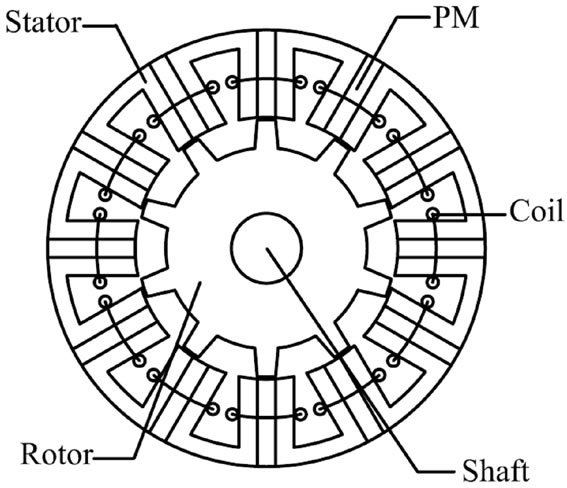
Figure 1. Topology of PMFSM
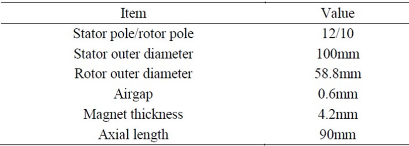
Table 1. Specification of the PMFSM
Though, Equation (1) was originally derived for the PM brushless motor, it has value of reference for the PMFSM. It reveals that the cogging torque can be reduced by controlling NL, GnNL, BnNL. Therefore, various design techniques can be applied.
3. Method of Reducing Cogging Torque
3.1 Rotor Tooth-Notching
Figure 2 shows the tooth-notching on the rotor. This changes the airgap between the rotor and stator, which can effectively control the airgap permeance function. Cogging torque can be reduced by applying proper number and depth of notches. Especially, two tooth-notches allocated on the 1/3 position of the rotor tooth is the most effective, as verified by FEA results.
3.2 Rotor Tooth-Chamfering
Figure 3 shows the chamfered rotor teeth. This also modifies the airgap permeance function. It makes sure that the flux in the airgap can vary much more smoothly. FEA shows that proper chamfer radius of arc can reduce the cogging torque significantly.
3.3 Rotor Teeth-Pairing
Figure 4 shows the rotor teeth pairing technique to reduce the cogging torque. The cogging torque waveform varies with the rotor tooth width br. By the way of example, if the width of all rotor teeth is br =8o, the cogging torque has almost the same waveform as the case when the width of all rotor teeth is br =11o, but opposite phase. Therefore, two types of rotor teeth with different width of br =8o and br =11o, are alternatively employed, as shown in Figure 4. The overall cogging torque can thus be significantly reduced, as verified by FEA results. Consequently, significant reduction of the cogging torque is observed.
Another way of realizing rotor teeth-pairing is to axially device the rotor stack into two parts. The width of all teeth in the first pant is r=11o, whilst that in the second part is r=8o. The cogging torque produced on these two parts will kill each other, such that the overall cogging torque will be reduced effectively. This method will not be mentioned in the next section.
3.4 Rotor-Skewing
Skewing is the most common method to reduce the cogging torque in PM machines. In the PMFSM, the stator has magnets, whilst the rotor is composed entirely of laminations. Therefore, skewing rotor is much more convenient in the PMFSM. In this paper, the rotor is skewed by one cogging torque cycle, viz. 6 mech-degrees. Finite Element Analysis (FEA) shows that rotor skewing can reduce the cogging torque by 95%. However, rotorskewing also decreases the rotor saliency, and thus reduces the back-EMF and electromagnetic torque.
3.5 Magnet Thickness Optimization
It was originally recommended in [2] that the magnet thickness should be the same as that of stator teeth. However, FEA shows that it is essential to optimize the magnet thickness to reduce the cogging torque. Generally, thinner magnets will lead to lower cogging torque, but also result in lower airgap field and electromagnetic torque.
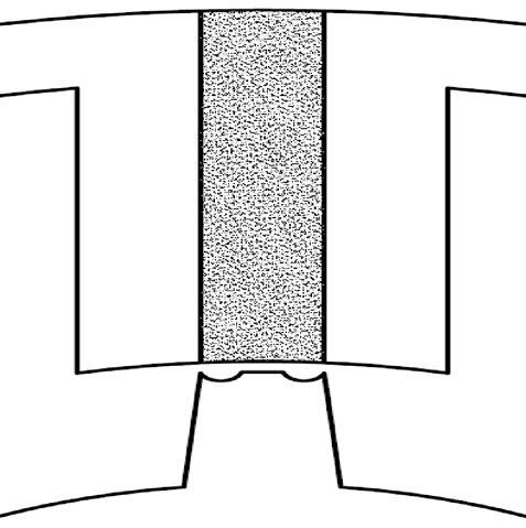
Figure 2. Rotor Tooth-Notching
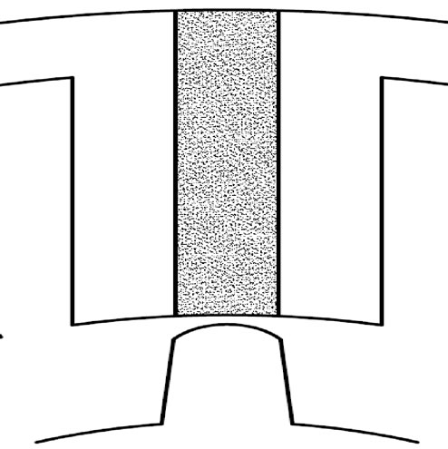
Figure 3. Rotor Tooth-Chamfering
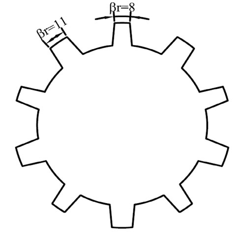
Figure 4. Rotor Teeth-Pairing
4. Effectiveness Analysis with FEM
In the preceding section, five design methods of reducing the cogging torque, as well as their pros and cons, have been presented. It is noted that the back-EMF may decrease when these methods are applied, therefore, the back-EMF variation should also be examined.
Figure 5 and Table 2 show the cogging torque reduction of the 12/10-pole PMFSM with various design methods. Compared with the case of the original model, the cogging torque can be reduced by 95% with the rotorskewing technique, and by 80% or more with the rotor teeth-pairing, rotor tooth-notching and rotor toothchamfering techniques. Using thinner magnets can also decrease the cogging torque, by 64%, though it is not sufficiently effective.
Figure 6 shows the back-EMF waveforms with half a cycle. It is seen that the back-EMF with rotor-skewing by 6 mech-deg is almost sinusoidal, and its amplitude decreases by 5% compared with that of the original model. The back-EMF with rotor tooth-notching contains more harmonics which can deteriorate the motor performance, and its amplitude is reduced by 12% due to the increase of the equivalent airgap length. Moreover, the airgap field with rotor tooth-chamfering or thinner magnets is smoother than that in the original model, thus, the back-EMF waveforms are also close to sine-wave. However, the rotor tooth-chamfering will decrease the backEMF, also because of the larger airgap. Furthermore, it is interesting to notice that the back-EMF amplitude with
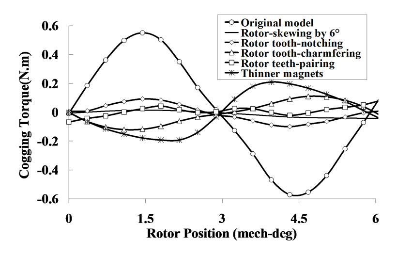
Figure 5. Cogging torque reduction with various methods

Table 2. Effectiveness of cogging torque reduction of various methods
width, which is the same as the magnet width and the stator tooth width as well as the stator slot opening width the rotor teeth-pairing technique increases by 4%. This further proves that the originally proposed rotor tooth [2], might be unsuitable. Hence, optimization of rotor tooth width is usually essential [6].
On the other hand, the PMFSM can be driven as a sine-wave permanent magnet synchronous motor (PMSM). Thus, the effective component of the back-EMF is the fundamental. Clearly, even if the amplitude of the phase back-EMF is high, its fundamental might not be essentially high due to the influence of harmonics. Therefore, the electromagnetic torque (EM-torque) produced with sine-wave armature currents are investigated. As can be seen in Figure 7, there exist ripples in the EM-torque, partly because of the harmonics in the back-EMF, and mainly because of the motor saliency and non-sinusoidal variation of winding inductance. The average EM-torque, as well as the back-EMF amplitude, is all listed in Table 3. It is seen that the rotor-skewing technique and thinner magnets technique will keep the average EM-torque almost the same, the rotor toothnotching technique and rotor tooth-chamfering techniques which increase the equivalent airgap length will reduce the average EM torque, whilst the rotor teeth-pairing technique can in contrast enhance the EM torque.
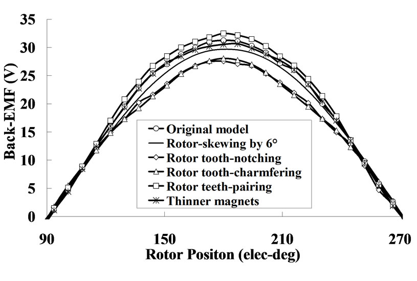
Figure 6. Back-EMF variation with various methods
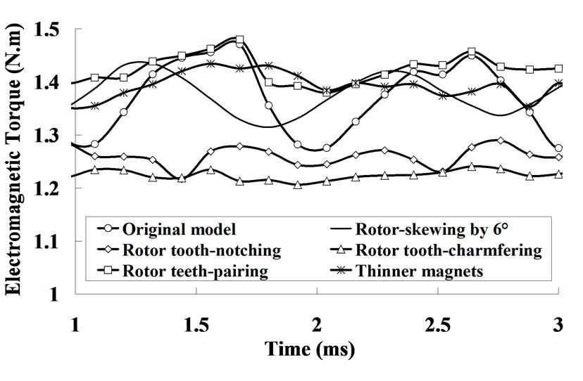
Figure 7. Electromagnetic torque variation with various methods
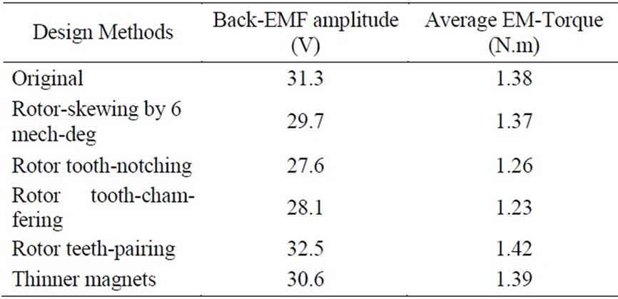
Table 3. Comparison of back-EMF and average torque with various methods
5. Conclusions
Five design methods are presented to reduce the cogging torque in the permanent magnet flux-switching machine. FEM is taken to analyze the effects of these methods, including the cogging torque reduction and the backEMF variation. It is proved that the rotor-skewing technique is the most effective to reduce the cogging torque and can keep the average EM-torque almost unchanged. Moreover, the rotor teeth-pairing technique can also reduce the cogging torque significantly, and meanwhile enhance the EM-torque by some degrees. These two methods are generally preferable.
REFERENCES
- S. E. Rauch and L. J. Johnson, “Design principles of flux-switching alternators,” AIEE Transactions, Vol. 74III, pp. 1261–1268, 1955.
- E. Hoang, A. H. Ben Ahmed, and J. Lucidarme, “Switching flux permanent magnet polyphased synchronous machines,” EPE-97 Conference, Trondheim, September 1997.
- H. Wei, M. Cheng, J. Z. Zhang, and X. Y. Zhu, “Optimal
- design of flux-switching permanent magnet machine based on finite element analysis,” Electromagnetic Field Computation, pp. 333–333, 2006.
- H. Wei, M. Cheng, Z. Q. Zhu, and D. Howe, “Analysis and optimization of back-EMF waveform of a novel flux-switching permanent magnet motor,” Electric Machines & Drives Conference, Vol 2, 3–5, pp.1025–1030, May 2007.
- Y. Amara, E. Hoang, M. Gabsi, M. Lecrivain, and S. Allano, “Design and comparison of different flux-switch synchronous machines for an aircraft oil breather application,” Proceedings 2nd IEEE International Conference on Signals, Systems, Decision and Information Technology, pp. 26–26, 2003.
- W. Z. Fei and J. X. Shen, “Novel permanent magnet switching flux motors,” 41st UPEC Conference, New Castle, pp. 729–733, September 2006.
- Y. Chen., Z. Q. Zhu., D. Howe. and Y. Y .Ye, “Starting torque of single-phase flux-switching permanent magnet motor,” IEEE Transactions on Magentics, Vol. 42, No. 10, pp. 3416–3418, October 2006.
- E. Hoang, A. H. Ben-Ahmed, and J. Lucidarme, “Switching flux permanent magnet polyphased synchronous machines,” Proceedings 7th European Conference Power Electron and Applications, Vol. 3, pp. 903–908, 1997.
- Z. Q. Zhu, Y. Pang, D Howe., S. Iwasaki, R. Deodhar, and A. Pride, “Analysis of electromagnetic performance of flux-switching permanent magnet machines by non-linear adaptive lumped parameter magnetic circuit model,” IEEE Transactions Magnetics, Vol. 41, No. 11, pp. 4277–4287, 2005.
- W. Hua, Z. Q. Zhu, M. Cheng, Y. Pang, and D. Howe, “Comparison of flux-switching and doubly-salient permanent magnet brushless machines,” Proceedings 8th International Conference on Electrical Machines and System, Vol. 1, pp. 165–170, 2005.
- S. M. Hwang, J. B. Eom, G. B. Hwang, W. B. Jeong, and Y. H. Jung, “Cogging torque and acoustic noise reduction in permanent magnet motors by teeth pairing,” IEEE Transactions Magnetics, Vol. 36, No. 5, pp. 3144–3146, September 2000.