Journal of Software Engineering and Applications
Vol.5 No.3(2012), Article ID:18289,10 pages DOI:10.4236/jsea.2012.53019
Analysis of Fusion Process Model—Case Study
![]()
Department of Computer Science, Punjabi University, Patiala, India.
Email: rupadeo@gmail.com
Received December 11th, 2011; revised January 14th, 2012; accepted February 20th, 2012
Keywords: Fusion Process Model; 3C-Model; Process Model; Component Driven Approach
ABSTRACT
Fusion Process Model is a software process model to enhance the software development process. Fusion process model has five fundamental phases and one fusion process controller to control and co-ordinate the overall development process. Fusion process model uses 3C-Model to generalize the process of solving the problem in each phase. 3C-Model, which helps in implementing component based development approach and provides firmer control over the software development process. Because of the component driven approach, the risk associated with cost and time is limited to component only and ensure the overall quality of software system, reduce the development cost and time by considering the changing requirements of customer, risk assessment, identification, evaluation and composition of relative concerns at each phase of development process. We have implemented fusion process model to the design of a real world information system and evaluated this implementation with the initial project estimation.
1. Introduction
A wide array of process models for organizing the process of software development has emerged over the last few decades. These process models represent patterns for successful development under different conditions. In current approaches, process control is performed on overall software process by decomposing the overall engineering process into phases. While decomposing overall engineering process into phases for effective and reliable development of software product, it is not sufficient. To handle cost, time, quality of software product and changing requirement of client, we need to control the internal process of each phase.
Anton Jansen and Jan Bosch [1] explain new perspective on software architecture that views software architecture as a composition of a set of explicit design decisions. This makes design decisions an explicit part of software architecture, which has become accepted concept in research and industry. The reuse model follows the component based approach, but this approach is not guided by domain analysis. It does not provide complete life cycle for software development because it considers only those systems which can be built using existing components only.
Jonathan Lee [2] describes the software engineering as a problem solving process. Where the software process model approaches divide the development process into various phases/activities or according to functionality. But these models still don’t follow the technique of technically analyzing the problem, where the technical problems are identified and divided into sub-problems that are first independently solved and later integrated into the overall solution. The client problems may be illdefined and include many vague requirements, but the main focus is on the precise formulation of objectives, quality criteria and the constraints for given requirement or problem. In technical analysis part, we can easily put this specification on each small unit of problem.
Providing a solution for a given problem is not simple, it involves the accumulation and use of huge amount of knowledge. The solution space analysis approach is still not integrated into software process models. It aims to identify the right solution domains for the given problems and extract the relevant knowledge from these domains to come up with a feasible solution. To provide quality software, it is necessary to identify the important knowledge sources for a given problem. Not all the solutions identified for a given problem are desirable. In the alternative management process, different alternative solutions are searched and evaluated against explicit quality criteria [2,3]. The high risk in software development led to the inclusion of managerial, financial and psychological factors in models [4,5], and [6,7]. Shaw and Garlan [8] identify seven levels of design specification capability which supports the concept of components, composition, validation, alternatives and finally automation. In the component based development, cost, time and reliability risk for an organization developing software system shrink to component level that can be managed effectively at any stage. The goal of the fusion process model is to address all the concerns and consider each phase of software development as the software development process and provide an effective model for software development phases, which will reduce risk associated with cost and time.
2. Fusion Process Model
Fusion is component driven software process model, where each phase implements a problem solving model. The problem solving model includes the explicit processes for technically analyzing the problem, solution space analysis, alternative analysis, dynamic design and development and scope for dynamic testing [9]. 3C-Model is problem solving model that enable generalizing the software development process in which a problem specification is transformed to a solution by decomposing the problem into sub-problems that are independently solved and integrated into an overall solution [10].
2.1. 3C-Model
3C Model consists of multiple cycles; each cycle in 3CModel corresponds to a trans-formation from one state to another, consisting of a problem specification state and a design state. The problem specification state defines the set of problems that still needs to be solved. The design state represents the tentative design solution that has been lastly defined. Initially, the design state is empty and the problem specification state includes the initial requirements. After each state transformation, a subproblem is solved. In addition a new sub-problem may be added to the problem specification state. Each transformation process involves an evaluation step whereby it is evaluated whether the design solutions so far (design state) are consistent with the initial requirements and if there are any additional requirements identified during the evaluation. The 3C-Model in development process divide the problem solving approach of each phase in three fundamental parts: Capture, Control, Context and Domain engineering, as shown in Figure 1.
2.1.1. Capture
The real problem is captured or a real problem is defined, which arise due to client requirements in this part. It comprises of five concepts: Need, Problem Description, Solution Domain Knowledge, Alternative, Solution Description and Artifact.
• Need represents an unsatisfied situation existing in the context (environment). The function Input represents the cause of a need.
• Problem Description represents the description of the problem. The function Conceive is the process of understanding what the need is and expressing it in terms of the concept Problem Description.
• Solution Domain Knowledge represents the background information that is used to solve the problem. The function Search represents the process of finding the relevant background information that corresponds to the problem.
• Alternative represents the possible alternative solutions. The function Generate serves for the generation of different alternatives from the solution domain knowledge. After alternatives have been generated, the problem description can be refined using the function Refine.
• Solution Description represents a feasible solution for the given problem. It uses the relevant background information to provide a solution description that conforms to the problem description. The function Detail is used to detail the description of a selected alternative.
• Artifact represents the solution for the given need. The function Implement maps the solution description to an artifact. The function Output represents the delivery and impact of the concept artifact to the context. The function Initiate represents the cause of a new need because of the produced artifact.
2.1.2. Control
The development process in software engineering starts with the need, while the goal is to arrive at an artifact by applying a sequence of actions. Since this may be a complex process, the concepts and functions that are applied are usually controlled. This is represented by the Control part in the model. The controller observes variables from the system, evaluates this against the criteria and constraints, produces the difference, and performs some control actions to meet the criteria.
• (Mathematical) Model represents a description of the concept Alternative. The function Analyze represents the process of analyzing the alternative.
• (Quality) Criteria represent the relevant criteria that need to be met for the final artifact. The function Evaluate assesses the alternative with respect to (Quality) Criteria and Constraints.
• Constraints represent the possible constraints either from the context or as described in the problem statement.
• Heuristics/Optimization Techniques represents the information for finding the necessary actions to meet the criteria and constraints. The function Select/Optimize selects the right alternative or optimizes a given alternative to meet the criteria and the constraints.
2.1.3. Context
Both the control and the problem-solving activities take

Figure 1. 3C-Model.
place in a particular context. Context can be expressed as the environment in which software development takes place including a broad set of external constraints that influence the final solution and the approach to the solution. Constraints are the rules, requirements, relations, conventions, and principles that define the context of software engineering, that is, anything, which limits the final solution. Since constraints rule out alternative design solutions directing engineers into taking action on what is doable and feasible.
The context also defines the need, which is illustrated by a directed arrow from the context to the need concept. Apparently, the context may be very wide and include different aspects like the engineer’s experience and profession, culture, history, and environment.
2.1.4. Domain Engineering
The phased model use domain analysis to identify domains, bounding them and discovering commonalities and variability’s among the systems. This information is captured in models that are used in the domain implementation phase to create artifacts such as reusable components, a domain-specific programming language, or application generators that can be used to build new systems in the domain. A key idea in systematic software reuse is the domain, a software area that contains systems sharing commonalities.
2.2. Five Fundamental Phases
Fusion process model consist of five fundamental phases and one fusion process controller to control and co-ordinate the overall development process, as shown in Figure 2.
2.2.1. Project Preparation
The project preparation phase provides the initial planning and preparation for software development project. Extracting the requirements of a desired software product is the first task in creating it. This process is called requirements elicitation. After requirements elicitation, client requirements are mapped to technical problems in the technical problem analysis process. The problem analysis process consists of the following steps: Generalize the
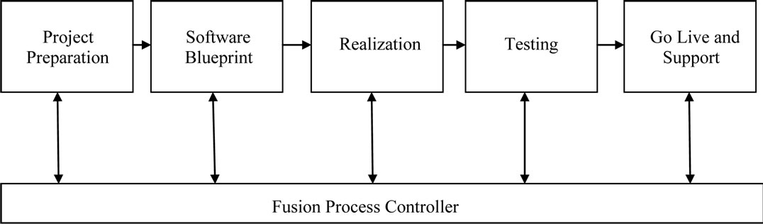
Figure 2. Fusion process model.
Requirements, Identify the Sub-Problems, Specify the Sub-Problems and Prioritize the Sub-Problems.
2.2.2. Software Blueprint
Architecture is established during the design phase. This phase starts with the inputs delivered by the initial phase and maps the requirements into architecture. The architecture defines the components, their interfaces and behaviors. The Solution Domain Analysis process applied in software design phase aims to provide a solution domain model that will be utilized to extract the architecture design solution. It consists of the following activities:
1) Identify and prioritize the solution domains for each sub-problem;
2) Identify and prioritize knowledge sources for each solution domain;
3) Extract solution domain concepts from solution domain knowledge;
4) Structure the solution domain concepts;
5) Refine the solution domain concepts;
6) Alternative design space analysis.
• Define the alternatives for each concept.
• Describe the constraints.
2.2.3. Realization
The purpose of realization phase is to develop a software system for requirements based on the software design. The team builds the components either from scratch or by composition. Given the architecture document from the design phase and the requirement document from the analysis phase, the team builds exactly what has been requested, though there is still room for innovation and flexibility.
2.2.4. Testing
Quality of software product is very important while developing it. In many software engineering methodologies, the testing phase is a separate phase which is performed by a different team after the implementation is complete. There is merit in this approach, it is hard to see one’s own mistakes, and a fresh eye can discover obvious errors much faster than the person who has read and re-read the material many times. Unfortunately, delegating testing to another team leads to a slack attitude regarding the quality of the implementation team.
Alternatively, another approach is to delegate testing in the whole organization. If the teams are to be known as craftsmen, then the teams should be responsible for establishing high quality across all phases.
2.2.5. Go Live and Support
The purpose of the Go Live and Support phase is to cut over to live productive operation and to continually support and improve live operations. There are two distinct periods of this phase: Project End and Continuous Improvement.
2.2.6. Fusion Process Controller
The controller part is not a phase in the process model, but it is an integral part of fusion process model. The controller part helps to achieve the component driven approach by listing the details of components which are added due to requirement changes or because of new requirements. By implementing Fusion Process Controller the current software development process will not be affected by changes required due to new requirements or modifications. The affected components can be taken care separately till these components matches with the current development process.
The remainder of the paper is structured as follows: Section 3 present a case study to aim at investigating the practical aspect of fusion process model. Section 4 presents the evaluation of the fusion process model with the initial project estimation. Section 5 discusses the results of fusion process model and lesson learned from these results. Finally, we conclude in Section 6.
3. Case Study of Fusion Process Model
The case study aimed at investigating the practical aspect of fusion process model and implementation in commercial Software Company. Clerisy Solutions is an Indian software company in Mohali. It specializes in software outsourcing and providing application system solution. Software project involved project manager, team leader and four developers and scheduled for over six months.
The project objective was to build a complex rights management system that can be used to provide services to all industry types. This was highly generic system that should allow an administrator to configure a system that is tailored for any rights marketplace. The rights management market was highly complex, with convoluted value chains with a wide range of variables affecting each potential assignment of rights or transaction e.g. a movie might have rights for cinema, DVD and online release in one hundred territories in seventeen languages, each at a different date and price, and each with a different liability in terms of the sums payable to distributors, producers, musicians, actors and producers. Often rights are locked out and a key feature of the system will be in finding what rights are available for what media in what territories so as to maximize the revenue potential for the right. The Figure 3 describes the relationship between various entities.
3.1. First Phase (Project Preparation) of Fusion Process Model
It is essential to first understand the requirements of the client. The two senior company employees were involved with client. Meetings were conducted with the client by the project manager and team leader to identify the requirements. Later these requirements were discussed with developers of the team. Based on the client inputs, the team prepared a “understanding document”. As a part of fusion process model developers were asked to raise questions based on the control part of the development process and a few important points come into light i.e. single/multiple client handling, online access, internationalization, separate logging mechanism. These queries were further discussed with client for refinement of the requirements and then again discussed with developers of the team. While pursuing phase model, team searched the solution domain knowledge to find out if any similar kind of project handled by the company previously based on the client inputs. Subsequently, found that the concept of this project is similar to the ERP project handled by the company, which has functionality already implemented for rights management.
The problem was generalized by dividing it into subproblems for further discussion like various important entities used in project development like user the owners and counterparts in the system, object is something that carries a right and rules can be applied to objects to make a right. Specified sub-problems were conversed with client to get more clarity of the problem. After that all the sub-problems/requirements were mapped with technical problems/requirements like: single/multiple client handling, online access, internationalization, separate logging mechanism, reporting structure, download formats (doc, xls, csv, pdf), create/delete/modify design for user, objects and rules, design for mapping users/object/rules, design for creation of various different type of reports, design for administrator rights, UI design as required by customer, database design, logs framework. This document was shared with the client and updated many times, to get an understanding of varied industry need, as development team need to make the software system highly generic to support all industry types.
Then team defined priority for various components like database design, complete UI design as required by customer, logs framework, internationalization support, user functionality, reporting functionality, application sign-in/sign-out, administration functionality design, object functionality, rules functionality, user/object/rules mapping, reporting functionality for other entities like rules/objects. Further decomposition was done on the above mentioned components and assigned to team members, depending upon the level of coupling team can parallel start working on different components. The problem analysis process mainly consists of the following steps:
1) Generalize the Requirements: whereby the requirements are abstracted and generalized;
2) Identify the Sub-Problems: whereby technical problems are identified from the generalized requirements;
3) Specify the Sub-Problems: whereby the overall technical problem is decomposed into sub-problems;
4) Prioritize the Sub-Problems: whereby the identified technical problems are prioritized before they are processed.
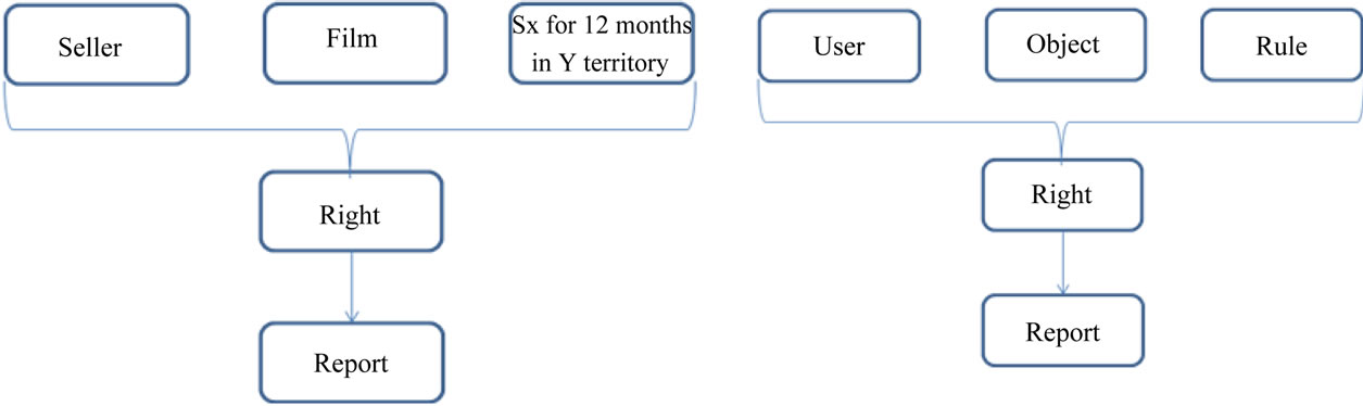
Figure 3. Software entity relationship diagram.
3.2. Second Phase (Software Blueprint)
Depending upon the inputs from the phase one, various design decision was taken after considering various alternatives based on the evaluation of control part in phase model. Team performed software design documentation, including Architecture design, Database design doc and Sequence diagram to understand initial flow.
Software design divided into various layers:
1) UI Layer;
2) Business Logic Layer;
3) Database access.
Further decomposing the three layers and prepared the documents for each low-level design requirement. The low-level requirements of each component were documented describing the technical implementation details including time frame and constraints (if any). Architecture document, which was the detail design document for each different component of project, was prepared. Then the priority for each component was defined and five reusable components were identified, as part of domain engineering in phase model. Identified re-usable components were:
1) Database access design;
2) Report download functionality (doc, pdf, xls, csv), once designed can be used for all the entities in the project;
3) Template design for various entities (User, Rules, Objects and Mapping), with little modification it can be used for all the entities;
4) Logs Framework;
5) Authorization mechanism (Sign-in/Sign-out).
Team found the three out of five components was already available with the company, which were:
6) Database access;
7) Log framework;
8) Authorization framework.
The design requirements were evaluated based on various mathematical models, quality techniques and optimization techniques defined by the development team based on company policies. Depending upon the technical complexities and other constraints, project manager and team leader specified time frame for each low-level component to keep track of cost/quality/time.
The software design process consists of the following steps.
3.2.1. Identify and Prioritize the Solution Domains
For the overall problem and each sub-problem, the search was executed for the solution domains that provided the solution abstractions to solve the technical problem.
3.2.2. Identify and Prioritize Knowledge Sources
Each identified solution domain covered a wide range of solution domain knowledge sources. These knowledge sources were not all suitable and vary in quality. For distinguishing and validating the solution domain knowledge sources team basically consider the quality factors of objectivity and relevancy. The objectivity quality factor referred to the solution domain knowledge sources itself and defines the general acceptance of the knowledge source. The relevancy factor referred to the relevancy of the solution domain knowledge for solving the identified technical problem.
3.2.3. Extract Solution Domain Concepts from Solution Domain Knowledge
Once the solution domains was identified and prioritized, the knowledge acquisition from the solution domain sources was initiated. Due to the large size of the solution domain knowledge, the knowledge acquisition process was a labor-intensive activity, so a systematic approach for knowledge acquisition was practiced.
3.2.4. Structure the Solution Domain Concept
The identified solution domains concepts were structured using parent-child relationship. Here all the attributes and operations associated with the concept were defined.
3.2.5. Refinement of Solution Domain Concepts
After identifying the top-level conceptual architecture, the focus was on each sub-problem and followed the same process. The refinement was necessary as the architectural concepts had a complex structure themselves and this structure was of importance for the eventual system. The ordering of the refinement process was determined by the ordering of the problems with respect to their previously determined priorities. Architectural concepts that represented problems with higher priorities were handled first and in the similar manner the refinement of the architectural concepts was done.
3.2.6. Alternative Design Space Analysis
After refinement of the solution domain, alternative space is defined as a set of possible design solutions. The alternative design space analysis aims to depict this space and consists of the two sub-processes: define the alternatives for each concept and describe the constraints.
3.2.6.1. Define the Alternatives for Each Concept In this approach the various architecture design alternatives were derived from well-established concepts in the solution domain that have been leveraged to the identified technical problems. The team identified various alternatives like report download API available with company or development of new reusable download API or third party paid tools, data access API or development of new component for data access, log framework. For translation (internationalization) team identified various alternatives like free online tool, paid translation tools, outsource to other translation professionals.
3.2.6.2. Describe the Constraints The total set of alternatives per concept was too large and/or not relevant for solving the identified problems. Therefore, to define the boundaries of the architecture it was necessary to identify the relevant alternatives and omit the irrelevant ones. Based on various constraints finally team selected report download API, data access API, log framework. All these components were already available with the company. After cost and time comparison the team decided that they can utilize the time of one resource for translation and finally free online tool was used for translation.
If any new requirement was raised by a client, independent of any other component, then the new component development process starts from the first phase. Finally after various reviews, time, cost and development details shared and finalized with the client to start the development process.
3.3. Third Phase (Software Realization)
Development started once client approved the design documents and development of components started based on the priority of component. Initially teams started working on two independent components UI design and database creation. As the client was extensively involved during the design phase, each small level detail was incorporated in UI design and database design after lot of modification before approval. Now, the team had clear vision for development. These components were immediately approved by client after completion. Now the base was ready to build a complete software system on it. The team started work on User entity and authorization part. The client was involved in the development also and a few minor modifications suggested by the client, which were immediately applied. After the development team evaluated these components and found that if they would have implement log framework and internationalization during development rather than considering it as an extra activity, they could have saved a lot of time in development and testing. All the customer suggestion and evaluation results were noted down for predecessor components. The team moved the component immediately to testing phase after completion of development. The testing results of each component were used as guidelines for the development and evaluation of other components.
Now we will summarize the software realization phase technically, the development team has a development project divided into various components, the development of components start based on the priority of component. Each component follows a different line of development and shared with the client to get the client feedback (requirement change/new requirement), before each cycle completes the development process. Each component is monitored using various control techniques defined by the development team to keep track of quality, cost and time. Once the development of any component complete, it immediately moves to testing phase.
3.4. Fourth Phase (Testing)
The complete software system design was based on component driven development approach. Each component directly moved to testing phase after the completion of development phase. There were various similar kinds of components in application; the test case used for one component was used with little or no modification for other components, which saved a lot of time required to build test cases. The test cases for reusable components were already available with the company, which were used to test various scenarios of application. Finally the integration testing was completed to deliver the complete software solution. Figure 4 shows the high level testing analysis.
The testing phase in the development process was to test the system to ensure that the developed product is error free. Quality of software product was very important while developing it. Many companies have not learned that quality is important and deliver more claimed functionality but at a lower quality level. It is much easier to explain to a customer why there is a missing feature than to explain to a customer why the product lacks quality. A customer satisfied with the quality of a product will remain loyal and waits for new functionality in the next version. Quality is a distinguishing attribute of a system indicating the degree of excellence.
The testing technique is from the perspective of the system provider. Because it is nearly impossible to duplicate every possible customer’s environment and because systems are released with yet-to-be-discovered errors, the customer plays an important, though reluctant, role in testing.
3.5. Go Live and Support
The purpose of the Go Live and Support phase was to cut over to live productive operation and to continuously support and improve live operations based on project agreements finalized with client. Finally the software deployed on customer landscape within projected cost and time. Due to component driven approach and customer involvement in each component, the software solution had all the required functionality.
3.5.1. Project End
During the time when the system was first live, all issues
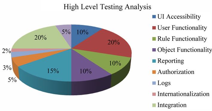
Figure 4. High level testing analysis.
and problems were resolved, transition to the production support team was finalized, knowledge transfer was completed and the project was signed off.
3.5.2. Continuous Improvement
Now that the project was over, the production support team monitors the system and resolves live business process issues. Proper change management procedures were established, and ongoing end-user training was conducted. Plans were made to continuously review and improve business processes.
4. Comparison of Fusion Process Model with Initial Project Estimation
Evaluation is performed with initial project estimation, initial estimation done by project management and development team using combination of various cost estimation model available and with the help of historical data, similar type of projects, customer requirements, complexity of the project, tools, languages, methodology, quality assurance procedures and standards etc.
The efficiency of any software development process model is based on how effectively it controls the development cost, quality and time. The principal components of project costs are hardware costs, travel and training costs, effort costs (the costs of paying software engineers). The dominant cost is the effort cost. This is the most difficult to estimate and control, and has the most significant effect on overall costs. Software costing should be carried out objectively with the aim of accurately predicting the cost to the contractor of developing the software.
Software cost estimation is a continuing activity which starts at the proposal stage and continues throughout the lifetime of a project. Projects normally have a budget and continual cost estimation is necessary to ensure that spending is in line with the budget. There are number of software cost estimation models are available, but no one method is necessarily better or worse than the other, in fact, their strengths and weaknesses are often complimentary to each other. According to the experience, it is recommended that a combination of models and analogy or expert judgment estimation methods is useful to get reliable, accurate cost estimation for software development.
The factors affecting the estimation for various different types of models based on the following criteria:
1) The component based development approach which helps to control overall development cost, quality and time;
2) The development and use of reusable software components;
3) How the software process model handles new and changed requirements of customer;
4) Time take for initial bug/issue identification and corrective measures;
5) Customer involvement at various stages of software development, to make the development process more stable;
6) Progress indicators provide information on how well the project is performing with respect to planned task completions and keeping schedule commitments;
7) Requirements Stability in software process model, which provides an indication of the completeness, stability, and understanding of the requirements.
When the team compare the final results with the estimation, they found 28% reduction in the actual cost of project, with the further analysis of results the team notice the difference in each phase of development process after implementing fusion process model, they were able to track, monitor and control the each component during the development process which helped them to control the overall cost, time and quality. Although team notice increase of effort in analysis and design phase due to implementation of 3C-model during these phase, but the extra effort during these phases result in overall requirement stability, control on rework, component reuse, component validation etc, which effect overall development process. Implementation of 3C-model result in the effort reduction of coding phase due less rework, requirement stability, reusable components and proper track of each development component. The Table 1 shows the Initial Project Estimation.
5. Results
Based on the judgments of the project manager and team leader on their individual experience, results where concluded. A lot of time spent on planning and design, as shown in Figure 5. But the time spent during first two phases help the development team to fully understand the requirements—problems/sub-problems till final level of decomposition. This decomposition helps in the final delivery of the product functionality and monitors the development process of each component separately at unit level to keep track of cost, quality and time schedule.

Table 1. Initial project estimation.

Figure 5. Effort estimation in each phase.
Most of the requirement changes and new requirements were clear during the first two phases, which were immediately incorporated in software design. As shown in Figure 6 effort estimation chart of design phase, more than 40% of design time spent on design change due new requirements or change in customer requirements.
If a flaw is found in the plan, major changes will need to be made during or after coding. This could result in a waste of productive time. As described earlier, majority of the rework happened in design phase only. Due to which the development team got the clear development vision. The rework done in coding phase estimate only 2% of entire development time or 6% - 7% of coding phase time, as shown in Figure 7.
The development process followed component driven approach, all the requirement changes or new requirement easily accommodated in development process. As development team was able to monitor the development at unit level, the problems identified at earlier stages and modified within scheduled time and cost. The Figure 8 describes the project stability based on changing requirement in each phase on monthly basis. The design phase starts in the second month and got 50% stability at end, because no major design changes happened after that. Major work in the coding phase starts in fourth month, got 85% stability in the end and so on.
Finally the testing team was able to work parallel to the development team on delivered component, bugs/ issue raised by testing team fixed during development and again delivered for testing phase. This insures the delivery of quality product within given time frame.
Lessons Learnt
The major lesson learned was:
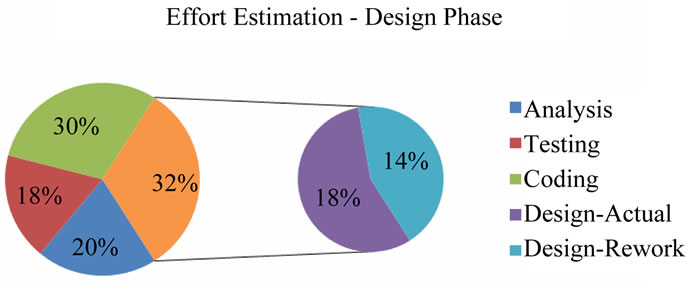
Figure 6. Effort estimation-design phase.
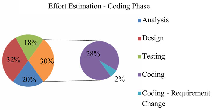
Figure 7. Effort estimation-coding phase.

Figure 8. Requirement stability monthly-design/coding/testing.
1) It was easy to track the time, cost and quality, due to component base approach. The new requirements or modifications were taken care separately till these components match with the development process. The controller part helped a lot by listing the details of components which were added due to requirement changes or because of new requirements;
2) Feedback and problem learnt from one component state to another state of a cycle was very helpful in applying to all other components. This saved lot of time due to which crucial time was utilized for other vital things of project;
3) User was involved, which helped in requirements elicitation and delivering all functionality of the project. One of the criteria, of the software project success depends on user involved from the start of the project and continuously throughout the development;
4) Guide line can be provided about Heuristics/Optimization Techniques in controller part, according to the model it depends on the organization to choice these techniques.
6. Conclusion
We have discussed a fusion process model for software development process and 3C-Model for each phase of development process model. Fusion process model includes an explicit phase for searching design alternatives in the corresponding solution space and selecting these alternatives based on explicit quality criteria. It has been implementation in commercial software company. The key results in this paper include the fusion process model, 3C Model, analysis of fusion process model and experience of project manager and team leader using fusion process model. The experience indicates results which demonstrate how this approach helps in controlling the overall development process by implementing component based approach. Fusion process model ensures the overall quality of software system; reduce the development cost and time by considering the changing requirements of customer, risk assessment, identification, evaluation and composition of relative concerns at each phase of development process.
REFERENCES
- A. Jansen and J. Bosch, “Software Architecture as a Set of Architecture Design Decision,” 5th Working IEEE/IFIP Conference on Software Architecture, Pittsburgh, 6-10 November 2005, pp. 109-120.
- J. Lee, “Software Engineering with Computational Intelligence,” Springer Publication, 2003, pp. 183-191.
- X. Ferre and S. Vegas, “An Evaluation of Domain Analysis Methods,” 4th CASE/IFIP8 International Workshop in Evaluation of Modeling in System Analysis and Design, 1999, pp. 2-6.
- B. Boehm, “Software Engineering Economics,” IEEE Transaction on Software Engineering, Vol. 10, No. 1, 1984, pp. 4-21. doi:10.1109/TSE.1984.5010193
- B. Boehm, “A Sprial Model of Software Development and Enhancement,” IEEE Computer, Vol. 21, No. 5, 1988, pp. 61-72. doi:10.1109/2.59
- A. Hamid and S. E. Madnick, “Lesson Learned from Modeling the Dynamics of Software Development,” Communication ACM, Vol. 32, No. 12, 1989, pp. 14-26.
- J. Ropponen and K. Lyytinen, “Components of Software Development Risk: How to Address Them?” A Project Manager Survey, IEEE Transaction on Software Engineering, Vol. 26, No. 2, 2000, pp. 98-112.
- N. Medvidovic and R. M. Taylor, “A Classification and Comparison Framework from Software Architecture Description Languages,” IEEE Transactions on Software Engineering, Vol. 26, No. 1, 2000, pp. 70-93. doi:10.1109/32.825767
- R. Kaur and J. Sengupta, “New Approach in Software Development-Fusion Process Model,” Journal of Software Engineering and Applications, Vol. 3, No. 10, 2010, pp. 998-1004. doi:10.4236/jsea.2010.310117
- R. Kaur and J. Sengupta, “Development and Analysis of 3C-Model for Software Development Lifecycle,” IEEE 2nd International Conference on Computer Engineering and Technology (ICCET 2010), Chengdu, 16-18 April 2010, pp. 688-691.