Positioning
Vol.05 No.04(2014), Article ID:51701,7 pages
10.4236/pos.2014.54013
Single Point Positioning Using GPS, GLONASS and BeiDou Satellites
Rock Santerre1, Lin Pan2, Changsheng Cai2, Jianjun Zhu2
1Department of Geomatic Sciences, Laval University, Quebec City, Canada
2School of Geosciences and Info-Physics, Central South University, Changsha, China
Email: rock.santerre@scg.ulaval.ca
Copyright © 2014 by authors and Scientific Research Publishing Inc.
This work is licensed under the Creative Commons Attribution International License (CC BY).
http://creativecommons.org/licenses/by/4.0/


Received 7 October 2014; revised 31 October 2014; accepted 24 November 2014
ABSTRACT
This paper introduces the Chinese BeiDou satellite system and its comparison with the actual completed American GPS and the Russian GLONASS systems. The actual BeiDou system consists of 14 satellites covering totally the Asia-Pacific area. A Single Point Positioning (SPP) test has been realised in Changsha, Hunan province, China, to show the advantage of using combined pseudorange solutions from these 3 satellite navigation systems especially in obstructed sites. The test shows that, with an elevation mask angle of 10˚, the accuracy is improved by about 20% in horizontal coordinates and nearly 50% in the vertical component using the simultaneous observations of the 3 systems compared to the GPS/GLONASS solution. For the processing with an elevation mask angle of 30˚, most of the time less than 4 GPS satellites were available for the GPS-only case and no solution was possible. However, in this difficult situation, the combined GPS/GLONASS/ BeiDou solutions provided an accuracy (rms values) of about 5 m.
Keywords:
BeiDou, GPS, GLONASS, Single Point Positioning

1. Introduction
The American GPS system has already been used for more than 20 years. Today GPS and GLONASS receivers are used on a day to day basis, especially by the professional users, since the Russian GLONASS constellation reached again a 24-satellite constellation. Many manufacturers already offer truly GNSS receivers capable of receiving also the European Galileo and the Chinese BeiDou satellites along with SBAS (Satellite Based Augmentation System) like WAAS satellites.
Galileo is still in construction phase with 4 actual operational satellites. BeiDou Navigation Satellite System (BDS) has provided standard navigation and precise positioning services ability in the Asian-Pacific regions since November 27th, 2012 [1] . The actual BeiDou constellation consists of 14 satellites [1] . The BeiDou full constellation should be completed by 2020 (and may be as soon as 2017).
This paper presents some SPP (Single Point Positioning) results obtained in kinematic mode in urban area using pseudorange observations from GPS (G) only, GPS and GLONASS (G/G) and combining GPS, GLONASS and BeiDou (G/G/B) satellites. The test has been realised in China where the BeiDou coverage is already completed. In addition, to simulate situations with difficult obstruction sites like in urban canyons and under tree covers (such as in forestry applications), the data have been reprocessed using a 30˚ elevation mask angle.
2. BeiDou Status and Comparison with GPS and GLONASS
BeiDou Navigation Satellite System (BDS) built by China independently has got the ability applying standard navigation and precise positioning services for the Asian-Pacific regions since November 27th, 2012 [1] . The word BeiDou means Big Dipper in Chinese language.
The actual BeiDou constellation consists of 14 satellites covering the Asia-Pacific region [1] . Five of them are geostationary (GEO) satellites (numbers 1 to 5 in Figure 1). Five satellites have an Inclined Geosynchronous Orbit (IGSO) giving the 8 shape trajectories in Figure 1 (numbers 6 to 10). Satellite numbers 11 to 14 (Figure 1) are Medium Earth Orbit (MEO) satellites like GPS and GLONASS satellites but with different orbital parameter values (see Table 1).
According to China government’s plan, the full constellation of BDS will include 5 GEOs, 3 IGSOs and 27 MEOs by the end of 2020, which will provide global navigation service similar to GPS and GLONASS [1] .
Table 2 presents the launch history of the actually operational BeiDou satellites. The other orbital characteristics of these satellites are given in Table 1 along with the comparison of the GPS, GLONASS and BeiDou systems. Table 1 content has been collected in [2] and [3] and the respective ICD documents.
The most important differences are the time scales and the coordinate systems used by these GNSS systems, which deserves more discussion.
The broadcast ephemerides are expressed in 3 different coordinate systems but fortunately they all are close together to the ITRF (International Terrestrial Reference Frame) at a few centimetres [4] . The accuracy of the GPS broadcast ephemeris is better than 1 m [5] . It is shown that GLONASS broadcast ephemerides have achie- ved stable sub-meter orbital accuracy [6] . Finally, [7] has showed that the broadcast ephemeris orbit accuracy of BeiDou system is better for non-GEO satellites than GEO satellites. The accuracy of BeiDou satellites orbit errors in radial direction is less than 1.5 m and 1.0 m for GEO and non-GEO satellites, respectively.
Since the time scales are different for the 3 navigation systems, one has to estimate a receiver clock parameter with respect to these time scales even if there is only a single receiver clock that assist the pseudorange (or carrier phase) observations. This means that for a Single Point Positioning with G/G/B receiver there are 6 parameters to estimate at each epoch, the 3D coordinates of the receiver (antenna) and the 3 receiver clock parameters. This is also the case in the calculation of DOP (Dilution of Precision) factors. In the future, GNSS satellites are going to broadcast precise time scale differences in their messages. In that case, only one receiver clock parameter will have to be estimated.

Figure 1. The actual BeiDou constellation (as produced with Trimble Planning software).

Table 1. Comparison of GPS, GLONASS and BeiDou systems.
Table 2. Operational BeiDou satellite launch dates and longitude of GEO and IGSO orbits. Source: http://gpsworld.com/the-almanac/.
The GNSS satellites are (are going) to broadcast on 3 frequencies, all of them close to the actual L1, L2 and L5 GPS frequency bands. The description of the codes and carriers used by GPS, GLONASS and BeiDou satellites can be found in the official ICD documents and several Internet sites (see the list of Internet sites at the end of this paper).
3. Test Description
A kinematic test was conducted on the campus road of the Central South University (N28.17˚, E112.92˚, H: 60 m), China, on December 22, 2013. The test was carried out from 7:45 to 9:15 GPS time (15:45 to 17:15 local time) for a duration of one and a half hour.
A car carried a Trimble NetR9 receiver with a Trimble Zephyr Model 2 geodetic antenna which allows simultaneous tracking of GPS, GLONASS and BeiDou signals. The sampling rate was 1 s and the observation elevation mask angle was 10˚ (even though the obstructions did not always permit the observation reception above 10˚). The used receiver can track code and phase observations on 3 frequencies but for the test purpose (Single Point Positioning: SPP), we only used single frequency code observations. Several loops of the same trajectory have been repeated (Figure 2). Each loop lasted about 5 minutes and the length of each loop was about 0.8 km. A car stop has been done between 8:30 and 9:00. The road is very close to mature trees and campus building (see Figure 2 and Figure 3) as typical urban conditions.
A similar receiver with a TRM55971.00 antenna with a radome was set up on the roof of the Mining Building of the Central South University as a base station to determine the reference coordinates of the rover moving vehicle from a RTK solution. The distance between the base and rover stations was less than 1 km. Most of the time, the RTK have ambiguity-fixed solutions providing a few centimetre positioning accuracy. But for some parts of the loops, the floated ambiguity solutions degraded the position accuracy to a few decimetres. For the purpose of SPP (Single Point Positioning) comparison, those reference positioning accuracies are still acceptable.
Figure 4 presents the satellite configurations at the beginning (7:40) and at the end (9:20) of the kinematic test, respectively (without the obstructions taken into account). The blue and the red-dot circles correspond to the 10˚ and 30˚ elevation mask angle, respectively. The GPS, GLONASS and BeiDou satellites are identified with circles of different colors in Figure 4.

Figure 2. Kinematic test trajectory on the CSU campus.


Figure 3. Receiver and antenna of the rover (left) and the base station (right).

Figure 4. Satellite polar plots at the beginning (left) and at the end (right) of the kinematic test. Source: Trimble GNSS Planning software.
4. Processing Strategies of the GNSS Code Observations
The Single Point Positioning (SPP) solutions has been done at every epoch (each 1 second) using only L1/G1/ B1 code (pseudorange) observations from GPS, GLONASS and BeiDou satellites, respectively. The data processing has been realized with the Multi-GNSS Integrated Positioning Software for SPP (MIPS-SPP) software developed and coded at Central South University (CSU).
Klobuchar model [8] along with the associated GPS broadcast coefficients have been used to correct L1 code observations for the ionospheric effects for GLONASS and BeiDou satellites as well. During the test, the TEC values reached about 50 TECU (Trimble Planning software). This value of 50 TECU (Total Electron Content Unit) corresponds to an 8 m delay (before corrections) for the L1 code observations for a satellite at the zenith. The tropospheric corrections have been taken into account with the Saastomoinen model [9] using standard meteorological values.
The satellite positions and clock error corrections have been calculated using their respective broadcast ephe- meris and satellite clock coefficients. Relativistic effects have been corrected and time group delays ( ) or differential code biases (DCB) have been properly applied for single-frequency code observations.
The weight P of a single satellite is assigned dependent on its elevation angle E [10] , as shown below:

The standard deviations
 of the GPS, GLONASS and BDS code observations were set to 0.3 m, 0.6 m and 0.3 m, respectively, i.e., their initial weight is 1:4:1 in combined G/G/B Single Point Positioning solutions. The readers can refer to [11] and [12] for an analysis of the standard deviations of BDS code observations. As mentioned above a receiver clock parameter has to be estimated, at every epoch, with respect to each system time scale.
To simulate heavy urban conditions, the processing has been repeated with a 30˚ elevation mask angle.
5. Analysis of the Test Results
The results are presented for the 10˚ elevation mask angle on the left and the 30˚ mask angle on the right in the following Figures and Tables. Keep in mind that due to the obstructions it does not mean that the satellite observations were possible down to 10˚ elevation angle. For each mask angle the results are presented for 1) GPS only (G), 2) GPS and GLONASS (G/G) and 3) GPS, GLONASS and BeiDou (G/G/B) observations.
Let us note that for the 30˚ mask angle and for the GPS only case, just a few epochs had more than 4 satellites available, so this solution is not presented at all. This fact effectively shows the advantage of using GNSS receiver under severe obstructed conditions like in urban canyons or under forest covers.
Figure 5 and Table 3 present the DOP values in the East (E), North (N) and Vertical (V) components and the Position Dilution Of Precision (PDOP) values for each processing cases along with the number of observed satellites. As expected, the values get better with the increase of the number of observed satellites. The stable DOP values between 8:30 and 9:00 GPS time is explained by the fact that the car was stationary during this period, so the obstructions do no change continuously during that interval. The numbers in parentheses in Table 3 indicate the improvement from the previous solution when the satellites of an additional constellation are added to the solution. Also, from a purely geometrical point of view, the DOP values increased (and the number of satellites decreased) as the elevation mask angle increased from 10˚ to 30˚.
Figure 6 and Table 4 show the position errors (with respect to the RTK solution as a reference) in the East (E), North (N) and Vertical (V or Up) components for each processing cases. Table 5 presents the RMS of the residuals for each constellation/system for the G/G/B solution for a 10˚ and 30˚ elevation mask angles, respectively.
Obvious offset in the North direction can be due to multipath effect from the buildings and trees along the road (trajectory) which is mainly in the East-West direction (see Figure 2). The improvement in the horizontal component reaches 10% with the addition of GLONASS satellites and another 20% more with the further addition of BeiDou satellites. The improvement in the vertical component was not really significant with the addition of GLONASS satellites but with the addition of BeiDou satellites the vertical improvement reached about 50%.
Table 4 shows an improvement of positioning accuracy in East and North components with a 30˚ mask angle compared to the 10˚ mask angle results, despite the fact that the EDOP and NDOP values get worse from 10˚ to 30˚ elevation mask angle (see Table 3). The reason may be that the satellites with low elevation angle which are seriously affected by the tree environments and produce larger multipath, noise and code residuals (see values in Table 5), are excluded when the elevation mask angle is set to 30˚. For the vertical component the RMS value is
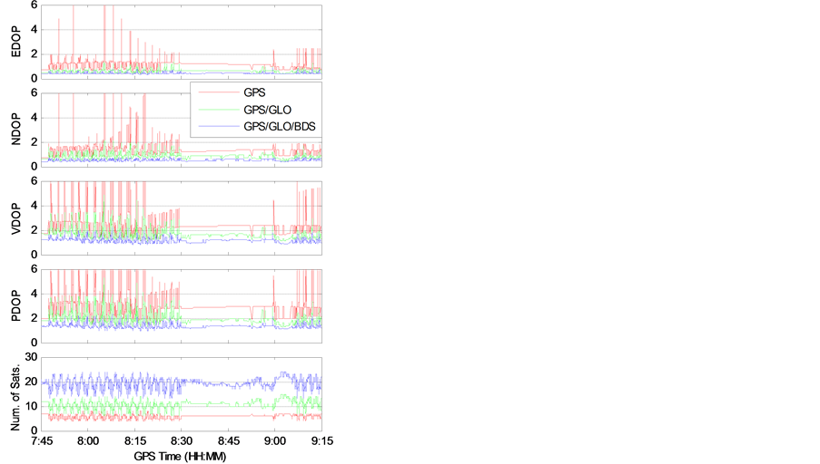

Figure 5. The DOP values and the number of satellites during the kinematic test for a 10˚ (left) and a 30˚ (right) elevation mask angles.
Table 3. Figure 5 averages values for the complete test (the numbers in parentheses indicate the % of improvement in comparison to the previous solution).


Figure 6. The East, North and Vertical (Up) position errors during the kinematic test for a 10˚ (left) and a 30˚ (right) elevation mask angles.
Table 4. Figure 6 RMS values for the complete test (the numbers in parentheses indicate the % of improvement in comparison to the previous solution).
Table 5. RMS residuals for each constellation for the GPS/GLONASS/BeiDou solution for a 10˚ (left) and a 30˚ (right) elevation mask angles.
larger for the 30˚ elevation mask angle solution but remains within the expected accuracy of a SPP solution even with a 30˚ elevation mask angle, typical of heavy obstructed conditions (like in urban canyons and under tree covers).
Finally, let us note that the RMS values of the code observations residuals of the BeiDou satellites are comparable to the one associated to GPS satellites. This is another indication of the good quality of the newly developed Chinese satellite navigation system.
6. Conclusions
The test shows that, with an elevation mask angle of 10˚, the accuracy is improved by about 20% in horizontal coordinates and nearly 50% in the vertical component using the simultaneous observations of the GPS/GLONASS/ BeiDou systems compared to the GPS/GLONASS solution. For the processing with an elevation mask angle of 30˚, most of the time less than 4 GPS satellites were available for the GPS-only case and no solution was possible. However, in this difficult situation, the combined GPS/GLONASS/BeiDou solutions provided an accuracy (rms values) of about 5 m.
The use of GNSS receivers will be the standard in the future even for low cost receivers. Some intelligent phones have already the BeiDou option included. The addition of satellites from Galileo, in construction, will further improve the accuracy, the coverage and the reliability of GNSS positioning, especially in obstructed observation sites.
Acknowledgements
The first author would like to acknowledge Laval University and Central South University for the partial funding of his sabbatical leave of absence in summer 2014 and the CSU GNSS Team for the fruitful discussions about BeiDou satellite systems. This research work has been supported by the freedom exploration program of Central South University (No. 2014zzts246).
References
- Gao, Z., Zhang, H., Zhao, Q., Hu, Z. and Shen, W. (2014) Analyzing the Impact of Satellite Clock-TGD Coupled Error on BDS Positioning Accuracy. In: Sun, J., et al., Eds., China Satellite Navigation Conference (CSNC) 2014 Proceedings: Volume I, Lecture Notes in Electrical Engineering Volume 303, 267-278. http://dx.doi.org/10.1007/978-3-642-54737-9_24
- Bhatta, B. (2011) Global Navigation Satellite Systems. CRC Press, Boca Raton.
- Jing, Y., Zeng, A. and Xu, T. (2014) Fusion Positioning of BDS/GPS Based on Variance Component Estimation and Its Application for Geodetic Control Network. In: Sun, J., et al., Eds., China Satellite Navigation Conference (CSNC) 2014 Proceedings: Volume I, Lecture Notes in Electrical Engineering Volume 303, 115-123. http://dx.doi.org/10.1007/978-3-642-54737-9_12
- Navipedia-ESA (2014). http://www.navipedia.net/index.php/Main_Page
- IGS-International GNSS Service (2014). http://igscb.jpl.nasa.gov/
- Heng, L., Gao, G.X., Walter, T. and Enge, P. (2011) Statistical Characterization of GLONASS Broadcast Ephemeris Errors. Proceedings of the 24th International Technical Meeting of the Satellite Division of the Institute of Navigation (ION GNSS 2011), Portland, September 2011, 3109-3117.
- Chen, L., Jiao, W., Huang, X., Geng, C., Ai, L., Lu, L. and Hu, Z. (2013) Study on Signal-In-Space Errors Calculation Method and Statistical Characterization of BeiDou Navigation Satellite System. China Satellite Navigation Conference (CSNC) 2013 Proceedings, Lecture Notes in Electrical Engineering, 243, 423-434. http://dx.doi.org/10.1007/978-3-642-37398-5_39
- Klobuchar, J. (1987) Ionospheric Time-Delay Algorithms for Single-Frequency GPS Users. IEEE Transactions on Aerospace and Electronic Systems, AES-23, 325-331. http://dx.doi.org/10.1109/TAES.1987.310829
- Saastamoinen, J. (1973) Contribution to the Theory of Atmospheric Refraction. Bulletin Géodésique, 107, 13-34. http://dx.doi.org/10.1007/BF02522083
- Gerdan, G.P. (1995) A Comparison of Four Methods of Weighting Double Difference Pseudorange Measurements. The Australian Surveyor, 40, 60-66. http://dx.doi.org/10.1080/00050334.1995.10558564
- Cai, C., Pan, L. and Gao, Y. (2014) A Precise Weighting Approach with Application to Combined L1/B1 GPS/Bei- Dou Positioning. Journal of Navigation, 67, 911-925. http://dx.doi.org/10.1017/S0373463314000320
- Cai, C., Gao, Y., Pan, L. and Dai, W. (2014) An Analysis on Combined GPS/COMPASS Data Quality and Its Effect on Single Point Positioning Accuracy under Different Observing Conditions. Advances in Space Research, 54, 818-829. http://dx.doi.org/10.1016/j.asr.2013.02.019
Other Internet Sites
GPS (official site): http://www.gps.gov/governance/excom/
GLONASS (official site in English): http://www.glonass-ianc.rsa.ru/en/
BeiDou (official site in English): http://en.beidou.gov.cn/
Interface Control Documents for GPS: http://www.losangeles.af.mil/library/factsheets/factsheet.asp?id=9364
Interface Control Document for GLONASS: http://gge.unb.ca/Resources/GLONASS%20ICD_2008_51en.pdf
Interface Control Document for BeiDou: http://www2.unb.ca/gge/Resources/beidou_icd_english_ver2.0.pdf
MGEX (IGS Multi-GNSS Experiment): http://igs.org/mgex/
Trimble GNSS Planning software: http://www.trimble.com/GNSSPlanningOnline/#/SatelliteVisibility