Engineering
Vol.5 No.1A(2013), Article ID:27321,10 pages DOI:10.4236/eng.2013.51A018
Incineration of Municipal Sewage Sludge in a Fluidized Bed Reactor
1Faculty of Environmental Engineering, Cracow University of Technology, Cracow, Poland
2Faculty of Chemical Engineering and Technology, Cracow University of Technology, Cracow, Poland
Email: *pczukows@pk.edu.pl
Received September 31, 2012; revised October 30, 2012; accepted November 11, 2012
Keywords: Biomass Power; Reburning; Nitrogen Oxides; NOx Reduction; Sewage Sludge; Fluidized Bed Combustion
ABSTRACT
In the present study reduction of nitrogen oxides using reburning technology, during combustion of sewage sludge (fuel I) and the mixture of sewage sludge, wasted bleaching earth and CaO (fuel II), was carried out. The experimental works were conducted in a laboratory-scale fluidized bed reactor (power up to 10 kW) with application of two types of beds: chemically inert bed (sand) and chemically active bed (CaO). The second combustion (reburning) zone in the reactor was formed by dosing into an area above the bed, additional gaseous fuel (propane). Obtained reduction in emissions of nitrogen oxides in both types of beds was at a level 70% - 79%. Additionally bed of CaO has the desulfurizing effect and also reduces the CO concentration in the exhaust fumes. A significant drawback of active bed is the adverse effect on increase of the primary NO which enters the second combustion zone. The result of this fact is higher NOx emission during combustion of the same fuel in bed of CaO in comparison to the combustion of this fuel in the sand bed, when the same maximum degree of reduction of NOx will be obtained for both types of beds.
1. Introduction
Application of combustion processes to thermal utilization of waste materials with a positive net calorific value is now considered as the best method of processing the high amount of wastes produced by human, as well as providing alternative, to fossil fuels, energy sources. For logistic reasons it is preferred to adapt to this processes relatively small-scale and low-complexity devices. In this case the emission of harmful substances into the atmosphere can be controlled, without extensive and expensive control at “end of pipe”, when utilized, in an appropriate condition, material has specific physical and chemical characteristics and can be used as an alternative fuel. However in a number of those cases we are dealing with fuels which have high nitrogen content (meat and bone meal, sewage sludge). Its thermal utilization causes high NOx concentrations in flue gases, what is environmentally and legally unacceptable.
Sewage sludge [1] is a growing environmental worldwide problem. In Poland in 1999 production of this waste was at level 354 Gg, in 2007 it was 533 Gg, while in year 2018 production is expected to be about 706 Gg [2]. The calorific value of the sludge can reach values of more than 20 MJ/kg [3], which is a relatively high value suggesting the thermal processing as one of their utilization method. So far, the most common method of sewage sludge disposal is landfilling or its use for fertilization. However, it seems that its agricultural application should be considerably reduced [4]. Solutions to the problem of managing sewage sludge should be sought in the areas of thermal utilization of this type of wastes, enabling a significant reduction of their volume and recover part of the chemical energy content from it in the form of heat. Also, the ashes remaining from the process can be a source of raw materials.
There are conducted worldwide extensive researches into different methods of thermal utilization of sewage sludge [5-15]. Some of these tests is carried out using a fluidized bed reactor, because of the advantages resulting from the specific hydrodynamic conditions of the bed. Such a reactor can be used for both the combustion of gaseous fuels and combustion of various types of waste materials [16-25].
The serious problem of sewage sludge combustion processes is, as mentioned earlier, the high content of nitrogen and sulfur in the processed material [26]. The result of this situation is that in the case of thermal processing of the sludge it is necessary to reduce the content of SO2 and NOx in the exhaust fumes. This can be implemented by adding fuel with a low content of sulfur and nitrogen to the sludge. Fuels that can be used are wasted bleaching earth, resulting from bleaching processes in the vegetable oils or paraffins refining industry. Bleaching earth except minerals contains moisture and inter alia, aliphatic and aromatic hydrocarbons or other organic compounds. The organic content in this waste causes that they are characterized by a relatively high calorific value—approximately 19 MJ/kg.
However, if the amount of nitrogen bounded in the sewage sludge is large, this solution is inadequate because the emission of nitrogen oxides from thermal utilization processes may be still too high. One of the methods which is used in order to obtain the concentration of NOx in the flue gases, in an amount at least harmful to the environment as it is possible, is introducing additional fuel into the zone of flue gases above first combustion zone and forming the second combustion zone—reburning zone [27]. Wendt with collaborators proposed in 1973 SO3 to SO2 and NOx to N2 reduction method. The necessary condition to occurrence of the reduction process in this zone is to create a reducing environment there. In such environment CHx, OH, CN and other radicals are presented. Those radicals are involved in the complex mechanism of NO reduction which is summarized described by the Equation (1):
2NO + C3H8 + 4O2 → N2 + 3CO2 + 4H2O (1)
Reburning since its inception, because of its advantages, has been and continues to be widely used. Wide applicability criterion makes continual researches on its modifications, in aim to obtain by its use flue gases of the best composition. In particular, the energy industry— one of the main NOx producers, uses this process as a method of removing nitrogen oxides from exhaust fumes [28-31]. Nitrogen oxides conversion rate which is achieved in the industrial installations of this type exceeds 70% [31]. One of the quite commonly applied reburning fuel is a gaseous fuel [32,33]. By using gas as a reburning fuel with suitably selected residence time of the reactants in the combustion chamber—350 MW plant-industrial scale boiler, the degree of obtained NO conversion was at the level excessing 60% [32].
The studies presented in this paper concern possibility of a significant reduction of NOx concentrations while simultaneous reducing of N2O concentration during the utilization of sewage sludge in a bubbling fluidized bed reactor of a simple construction, by the action of two kinds. First was introduction of additional gaseous fuel (propane) into the zone above fluidized bed (freeboard zone) and organizing there second combustion zone (reburning zone). Combustion of pure sludge under these conditions resulted in a significant reduction in levels of NOx and N2O, but not allowed to obtain such a low NOx concentration values which are environmentally acceptable. Therefore it was proposed to use a fuel composed of two types of waste: sewage sludge (with a higher nitrogen content) and wasted bleaching earth obtained from the refining of oils (with very low nitrogen content) with desulfurizing agent (fuel II). The aim of latter studies was to determine the range of air excess coefficient in reburning zone—lr, by which sufficiently low concentration of NOx in flue gases, while reduction of N2O and absorption of SO2 in the bed is achieved.
2. Experimental
2.1. Characteristic of Applied Fuels
The main component of the two types of fuels used in the studies was dried municipal sewage sludge in form of granulate. Fuel I is pure sewage sludge. The advantage of chosen material is uniform composition of the precipitate, a small moisture content and easiness of formulation of granulate. The disadvantage is a larger amount of organic substances containing nitrogen and sulfur per mass unit fed to the reactor and a small content of coarse mineral fractions, which are a natural component reproducing inert bed. The second type of fuel (fuel II) was a mixture made up of dried sewage sludge, wasted bleaching earth and lime. The high sulfur content in the sludge resulted in addition, to the fuel II, substance reacting with SO2- calcium carbonate. Application of this compound allows to use the fluidized bed to SO2 absorption. Elementary composition of fuels, mineral content and heat of combustion of both materials subjected to the combustion process are presented in Table 1. The content of the elements: C, H and N in the sample has been determined using a method based on Pregl-Dumas analyzer PerkinElmer 2400 Series II CHNS/O Elemental Analyzer. Mineral content has been set by incinerating the sample and then calcinating the residue to constant weight in a chamber furnace at a temperature of 815˚C. The heat of combustion has been determined by calorimetric method.
Conducted analyzes show that fuel I has a very high nitrogen content, but it does not deviate significantly from the nitrogen content of other dry sewage sludge [26] (Table 1). Preparation of the sludge to thermal transfor
Table 1. Fuels composition and heat of combustion.
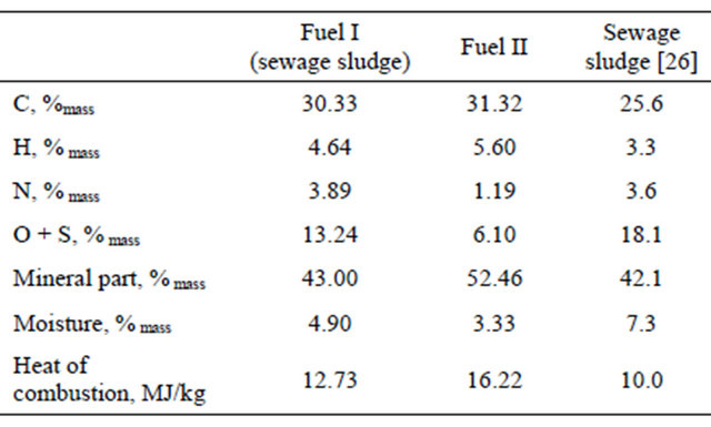
mation in the fluidized bed reactor consisted of extracting the fraction with appropriate particle size, providing a reasonable period of particles residence in the combustion zone-sufficient to complete of oxidizing of combustible substances in material. By carrying out preliminary tests it has been established that those conditions are fulfilled by the fraction of grains with a diameter of 0.5 - 2.0 mm.
Fuel II was composed of municipal sewage sludge (30%mass), wasted bleaching earth (62%mass) and CaCO3 (8%mass), the intended particle size and dosage form suitable for fluidized-bed reactor have been obtained in several subsequent operations. After crushing pieces of municipal sewage sludge to a smaller diameter grains, it has been isolated fraction of grains with a diameter of 0.3 - 4.0 mm. Then a measured amount of bleaching earth from refining paraffin wax has been melted in a water bath. To liquefied in this way wasted bleaching earth prepared in advance municipal sewage sludge and calcium carbonate have been gradually added, all mixed and grinded. From obtained granulate grains with a diameter of 0.3 - 4.0 mm have been sieved.
2.2. Equipment and Procedure of Researches
Thermal utilization of fuel I and fuel II has been conducted in laboratory scale ABFB reactor (capacity of about 5 kW, Figure 1). Fluidized bed reactor was made of a quartz tube, which outer diameter is 96 mm, wall thickness is 2 mm and height is 500 mm, set on a perforated steel plate with a thickness of 1 mm, which was a distributor of air and gaseous fuels. The temperature regulation system was composed of moveable radiation shield, limiting the heat losses to the environment and of the cold air blower (Figure 1). To measure the temperature in the fluidized bed two fixed thermocouples were used mounted at a height of 20 and 50 mm above the distributor. The temperature in the second combustion zone has been measured by 8 thermocouples mounted in the axis of the reactor one above another (Figure 1): in
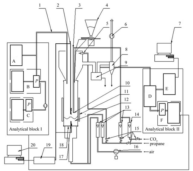
Figure 1. Schematic representation of the fluidized bed reactor. 1, Heated probe for sampling the flue gases; 2, Set of 8 thin thermocouples; 3, Reburning fuel’s supply system; 4, Batcher; 5, Pilot flame; 6, Exhaust fan; 7, Computer storing data from Gasmet DX-4000; 8, Cyclone; 9, Ash trap for coarser particles; 10, Outlet of reburning fuel; 11, Movable radiation shield; 12, Fluidized bed; 13, Rotameters (from left: air and primary and secondary fuel); 14, Rotameter of CO2; 15, Fuel supply valves (from left: fuel supplying the pilot flame, reburning fuel, total fuel, CO2); 16, Blower; for fluidising air; 17, Two thermocouples; 18, Flat, perforated metal plate distributor; 19, A/D convertor for thermocouple signals; 20, Computer storing chemical analyses quantities and temperature. Analytical block I: A, Total organic compounds analyser (JUM Model 3-200); B, ECOM SG Plus; C, Horiba PG250; P, Peltier’s cooler. Analytical block II: D, Mobile conditioning system of Gasmet DX-4000; E, Analyser FTIR (Gasmet DX-4000); F, MRU Vario Plus.
the case of fuel I combustion at a distance of 148 mm to 213 mm, while for the fuel II incineration at a distance of 131 to 196 mm above the distributor. Reburning fuel dosage system consisted of a pipe supplying gaseous fuel finished by eight nozzles arranged in a parallel plane to the distributor, 155 mm above it (Figure 1). Protection of the nozzles from clogging was assured by continuously flowing through them small amount of CO2 stream. In the experiment with the combustion of fuel I the bed in the reactor was made by sand-mass of 150 g and 0.385 - 0.43 mm grain size. During combustion of fuel II bed was mad of limestone weighing 100 g and with grain size of 1.2 - 1.5 mm.
During the process the composition of gases leaving the second combustion zone (reburning zone) has been continuously recorded. Analytical devices which have been used in this aim were divided into two blocks (Figure 1). The analytical block I consisted of analyzers: JUM Model 3-200 (analyzer of volatile organic compounds-VOCs), ECOM SG Plus, Horiba PG250. Flue gases have been collected by heated probe, which inlet was mounted approximately 460 mm from the distributor. The analytical block II (Figure 1) consisted of the analyzers: Gasmet DX-4000 and MRU Vario Plus. Exhaust fumes which have been sent to the block were partly dust-free, after dust removing in ash trap for coarser particles, and mixed with secondary air, which was necessary to adapt concentration of gaseous compounds in exhaust fumes to the measuring range of FTIR analyzer. The main task of the MRU analyzer was to allow determining the degree of dilution of exhaust fumes by secondary air.
The conducted experiments started from warming up the fluidized bed by combustion of propane (0.056 ± 0.001 dm3/s) and air (1.66 ± 0.08 dm3/s) mixture. After the bed temperature reached about 800˚C dosing of solid fuel has been started with a simultaneous decrease of the of propane flow into the reactor. Utilized material has been dosing into the reactor using a batcher with the intensity of approximately 25 g/min in experiment I and about 16 g/min in experiment II. Bed heating stage was finished by cutting-off propane flow to the first combustion zone—the only heat source was then combusting solid fuel. Next stages in each experiment consisted of solid fuel combustion with or without simultaneous conducting of reburning process. The selected parameters of the processes are shown in Table 2.
3. Results and Discussion
Basing on the analytical data which were obtained, temporary and average values of air excess coefficient in the reburningu zone—λr (characterizing the different stages of process in the reactor) have been calculated. The calculations were done using the relationship derived and published in the prior article [20]. Derivation of the λr is added as an attachment to this paper. During the combustion of fuel I and fuel II, without creating a second combustion zone, the air excess coefficient was maintained respectively in the range of 1.3 - 1.6, (Figure 2(a)) and 1.6 - 2.0 (Figure 2(b)). For optimal effect of reburning the combustion process should be conducted in the way to obtain air excess coefficient close to 1.0 in the second combustion zone.
Analysis of the results of the temperature measurement in the zone above the fluidized bed during the combustion of fuel I shows that, before the creation of the second combustion zone, temperature in freeboard of the reactor is about 80˚C - 100˚C higher than in the bed (Figure 2(a)). During fuel II combustion this difference was about 20˚C - 40˚C (Figure 2(b)). The reason for this phenomena was the lifting of sewage sludge small fractions and not yet combusted agglomerates of sludge, which during the combustion process were transferred to freeboard zone of the bed, where have been combusted. Fuel II, although it contained a readily volatile compounds, behave better cohesiveness and its greater part have been burned in the bed.
Creation of the second combustion zone by dosage of additional fuel into the zone above fluidized bed (freeboard zone) resulted in an increase of CO2 in the flue gases from approximately 15% to 20% during the combustion of fuel I (Figure 3(a)) and from about 11% to
Table 2. Process data of fuel I and fuel II combustion.
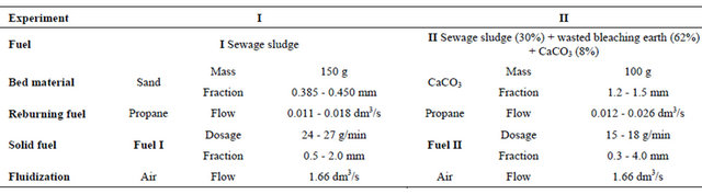
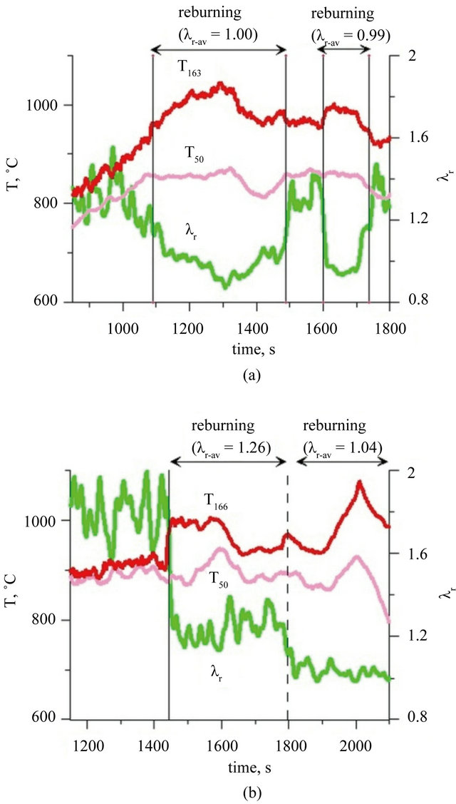
Figure 2. Temperature and air excess coefficient in reburning area during combustion of: (a) fuel I; (b) fuel II (Indexes: r: in reburning area; r-av: average value in reburning area).
17% when fuel II has been combusted (Figure 3(b)). The observed oscillations of the concentration of CO2 (and other exhaust components) are caused by transient changes in the amount of the solid fuel, caused by dosing fuel grains of not exactly the same sizes.
During one zone combustion of fuel I and II average CO concentration in the exhaust fumes was respectively 6500 and 2150 ppm whereas the stream of fuel II was about 1/3 smaller than the stream of fuel I. Disproportional low concentration of CO during combustion of fuel II, in relation to size of the C stream in fuel dosed to the reactor is not surprising. This effect was caused by catalytic effect of Ca in a fluidized bed of lime [34]. The result of drastic decrease of the oxygen content in the second combustion zone, after reburningu start, leads to limitation of oxidation of hydrocarbons to CO and CO to
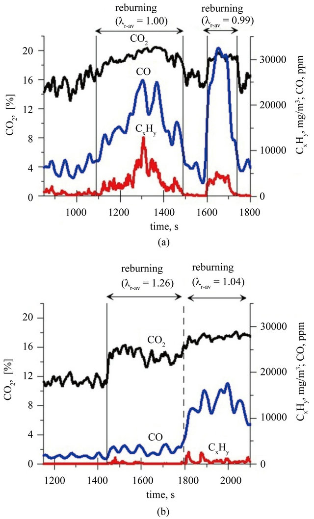
Figure 3. Concentrations of CO2, CO and total organic compounds during combustion of: (a) fuel I; (b) fuel II (Index: r-av: average value in reburning area).
CO2 in reburning area. It was reflected in an increase in CO and hydrocarbons concentration in the flue gases (Figure 3). It is characteristic that among hydrocarbons in the exhaust fumes from period when two zone combustion has been conducted, there were not presented propane and ethane (their concentration was below the FTIR analyzer detection limit). Concentrations of other hydrocarbons containing to two carbon atoms—were at very similar levels for both cases: combustion fuel I in the bed of sand and combustion fuel II in the bed of lime (Figure 4). Ethene, ethyne and methane are products of structural degradation of propane and are a source of CHx radicals which play a primary role in the reburningu process [27]. There was no significant relationship between the concentration of methanol, formic acid and formaldehyde in the flue gases and a type of the bed used the combustion of fuel I and II. Concentration of formaldehyde in the exhaust fumes fluctuated in the range of 80 - 100 ppm, methanol did not exceed 10 ppm and formic
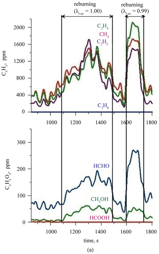
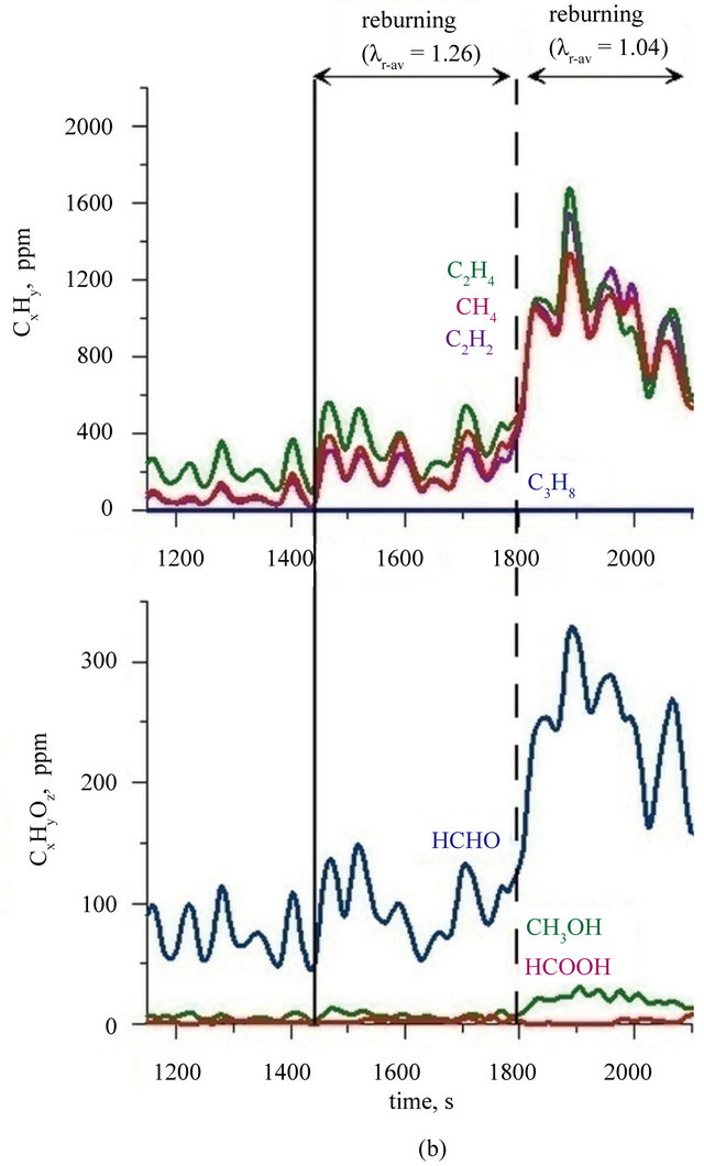
Figure 4. Concentrations of chosen organic compounds during combustion of: (a) fuel I; (b) fuel II (Index: r-av: average value in reburning area).
acid concentration fluctuated at the detection limit. During the two zone combustion of fuel I when the value of air excess coefficient reached a value of 1.0 methanol concentration was about 50 ppm (Figure 4(a)) and while the combustion of fuel II in a bed of lime—30 ppm (Figure 4(b)). Concentration of formaldehyde (regardless of the type of bed and fuel) reached under these conditions a value of about 270 - 300 ppm. Calculations indicate that in the reburning zone content of C1 - C3 hydrocarbons is not more than 20% of the amount of reburning fuel dosed into the reactor, but their presence indicate a significant advancement of propane decomposition processes involving radicals favourable for NOx reduction process.
Determination of the real concentration of SO2 in the flue gases meets serious analytical problems. Electrochemical sensors used in analytical devices show significant cross-sensitivity of SO2 sensors for gases like H2S or C2H4 [35]. These substances may be presented in significant quantities during the combustion of fuels which contain sulfur, especially in conditions of limited oxygen access. Such conditions occurred during conduction of presented researches. In separate experiments [36] it was showed that during the combustion of propane in the fluidized bed reactor products may include unsaturated hydrocarbons and aldehydes C1 - C4. The latter show intense IR absorption of radiation in the range of 1000 - 1800 cm−1, completely covering the typical range of SO2 absorption (1150 - 1450 cm−1). It represents a serious obstacle to assume process of IR radiation absorption as a reliable method of determination of SO2, in the flue gases with low oxygen content. During the combustion of fuel II it has been introduced, to the reactor, in the form of the bed and as a fuel component CaO, in amount of about 1.33 mol and not more than 0.40 mol of sulfur bounded in the fuel II. Under those conditions nearly complete sorption of SO2 should occur. Recorded changes in SO2 concentration in the flue gases do not look like a result of decreasing conversion of sulfur introduced to the reactor. Figures 5(a) and (b) shows the recorded changes in SO2 concentration in the exhaust fumes, measured with application of an electrochemical sensor. Both during the combustion of fuel I and fuel II the observed changes in SO2 concentrations are not cor-
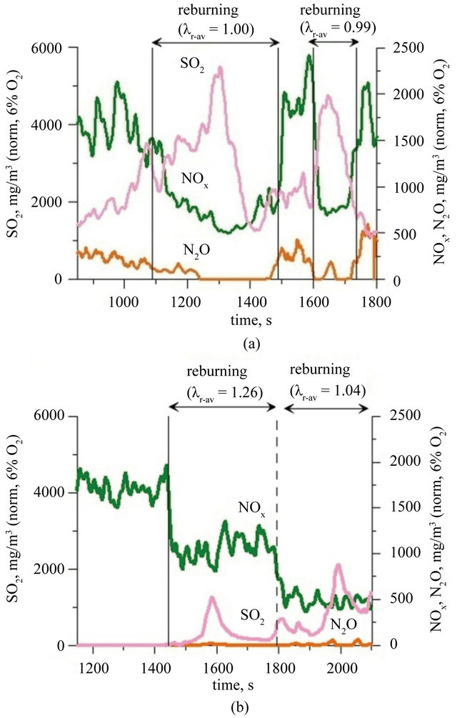
Figure 5. Concentrations of SO2, NOx and N2O (data standardized for 6% O2 in flue gases) during combustion of: (a) fuel I; (b) fuel II (Index: r-av: average value in reburning area).
related with changes in the fuel stream, while they correspond well to the changes in concentrations of ethene, ethyne, methane and oxygen derivatives of methane in the exhaust fumes and also to the changes of the value of air excess coefficient in reburning area. Variations of the value of λr have no effect on the oxidation of sulfur bounded in the fuel, because these reactions take place in the fluidized bed not in the reburning zone. That leads to conclusion that only results of SO2 analyzes obtained during one zone combustion have minor error caused by a small concentration of C1 - C3 hydrocarbons and their oxygen derivatives. It was found that during one zone combustion of sewage sludge in a bed of sand concentration of SO2 in the flue gases reaches a value of 2000 - 3000 mg/m3, while during combustion in the CaO bed it does not exceed 30 mg/m3 (Figure 5). Such a concentration of SO2 in the exhaust fumes indicates a high efficiency of conducted desulfurization process directly in the fluidized bed.
During one zone combustion of fuel I in a fluidized bed of sand concentration of NOx and N2O in the exhaust fumes has changed (values standardized to 6% of O2 in the flue gases) respectively in the range 1400 - 2100 mg/m3 and 150 - 250 mg/m3 (Figure 5(a)). Creation in freeboard of the reactor, above fluidized bed, of the second combustion zone resulted in a reduction of the concentration of those compounds to a value of respectively 450 - 500 mg/m3 and 10 - 200 mg/m3 (Figure 5(a)). Although lowering the air excess coefficient to a value of 1.0 in the second combustion zone, NOx concentration value lower than 400 mg/m3 was not achieved. Taking into consideration Polish law involving limits for NOx concentrations in exhaust fumes for this type of process, it was necessary of co-combustion this waste with other flammable components (with low nitrogen content) or assumed necessity of building a more complicated system of nitrogen oxides reduction. During one zone combustion of fuel II in the fluidized bed of CaO, NOx and N2O concentration in exhaust fumes was respectively within the range of 800 - 1700 mg/m3, and 0 - 20 mg/m3 (Figure 5(b)). The concentration of NOx was greater than expected when taking into consideration that the nitrogen content in the fuel II was three times lower than in the fuel (cf. Table 1). The reason of this phenomena are catalytic properties of CaO in the oxidation process of nitrogen bounded in the fuel. Hayhurst and Lawrence prove in their work [37] that even 2% addition of calcium oxide to bed of sand may cause as much as twentyfold increase in the rate of NOx formation, while slightly reducing N2O emissions. The key step in process of creation of NO is oxidation of CN radicals, absorbed at the surface of grains, to CNO. The process is finished by CNO oxidation process to CO and NO. The creation of the second combustion zone during fuel II combustion did not cause significant changes in the concentration of N2O in the exhaust fumes which remained within value 0 - 20 mg/m3 (Figure 5(b)). The concentration of NOx in the flue gases, when the air excess coefficient was reduced to 1.04, decreased to 500 ± 100 mg/m3 (Figure 5(b)). The efficiency of reburning process was evaluated by determining the degree of reduction of nitrogen oxides concentration:
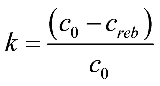 (1)
(1)
where:
c0: Concentration of NOx in flue gases during one zone combustion;
creb: Concentration of NOx in flue gases during two zone combustion;
where both c0 and creb were calculated at the same O2 concentration in the flue gases The dependence of degree of reduction of nitrogen oxides concentration from the air excess coefficient in reburning zone is shown in Figure 6. During the two zone combustion NOx degree of reduction is always higher of fuel II. The maximum degree of reduction of the NOx concentration was 78% at lr = 1, while for fuel I the maximum value of degree of reduction is equal 70%, with air excess coefficient in the reburning zone—lr close to 0.9.
4. Conclusions
Studies have shown that combustion of sewage sludge containing high fuel-nitrogen content, in a small-scale fluidized bed reactor with bubbling fluidized bed is a significant source of NOx emissions. Application of the solution based on creating the second combustion (reburning) zone, under these conditions, provides benefits such as significant reduction of the amount of produced, in first combustion zone, nitrogen oxides (up to 79%). Reducing the nitrogen content in fuel by mixing it with additional fuel which contains only small amounts of nitrogen or nitrogen-free, makes possible to make further reduction of NOx concentration in flue gases, both during the one and two zone combustion. Combination of the two solutions allows for reduction of NOx concentration to require level.
Simultaneously decline of SO2 concentration can be achieved by combustion of mixture of fuel with CaCO3, as the compound which reacts with SO2. Nevertheless adverse effect of CaO catalytic activity on reaction of nitrogen oxides (NOx) formation was observed and must be taken into account. It was also observed that in the
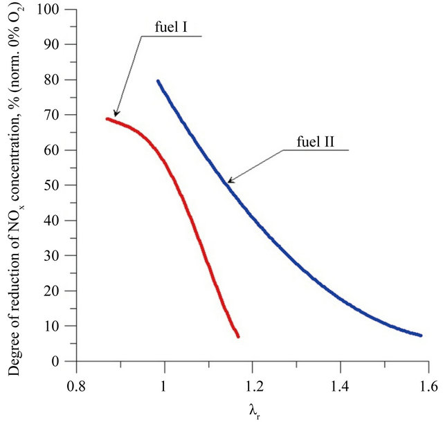
Figure 6. Degree of reduction of NOx concentration depending on air excess coefficient in reburning area related to comparable conditions—0% O2 in flue gases.
presence of CaO concentrations of carbon monoxide and nitric oxide were lower than when combustion was conducted without its participation.
REFERENCES
- European Comission, “Environment,” 2012. http://ec.europa.eu/environment/waste/sludge/index.htm
- Poland, “The 2010 National Waste Management Plan,” Warsaw, 2006.
- Y. J. Kim, H. O. Kang and T. I. Qureshi, “Heating Value Characteristics of Sewage Sludge: A Comparative Study of Different Sludge Types,” Journal of the Chemical Society of Pakistan, Vol. 27, No. 2, 2005, pp. 124-129.
- Council, “Protection of the Environment, and in Particular of the Soil, When Sewage Sludge Is Used in Agriculture,” Council Directive 86/278/EEC, 12 June 1986.
- F. J. Tian, B. Q. Li, Y. Chen and C. Z. Li, “Formation of NOx Precursors during the Pyrolysis of Coal and Biomass. Part V. Pyrolysis of a Sewage Sludge,” Fuel, Vol. 81, No. 17, 2002, pp. 2203-2208. doi:10.1016/S0016-2361(02)00139-4
- L. Shen and D. K. Zhang, “An Experimental Study of Oil Recovery from Sewage Sludge by Low-Temperature Pyrolysis in a Fluidised-Bed,” Fuel, Vol. 82, No. 4, 2003, pp. 465-472. doi:10.1016/S0016-2361(02)00294-6
- S. Fairous, S. Rusnah and H. Maryam, “Potential Source of Bio-Fuel from Pyrolysis of Treated Sewage Sludge,” Proceedings of the 2010 International Conference on Science and Social Research (CSSR 2010), Kuala Lumpur, 5-7 December 2010, pp. 1272-1277. doi:10.1109/CSSR.2010.5773732
- B. Groß, C. Eder, P. Grziwa, J. Horst and K. Kimmerle, “Energy Recovery from Sewage Sludge by Means of Fluidised Bed Gasification,” Waste Management, Vol. 28, 2008, pp. 1819-1826. doi:10.1016/j.wasman.2007.08.016
- J. J. Manyá, J. L. Sánchez, J. Àbrego, A. Gonzalo and J. Arauzo, “Influence of Gas Residence Time and Air Ratio on the Air Gasification of Dried Sewage Sludge in a Bubbling Fluidised Bed,” Fuel, Vol. 85, No. 14-15, 2006, pp. 2027-2033. doi: 10.1016/j.fuel.2006.04.008
- J. Baron, “The Bubbling Fluidized-Bed Reactor Used to Solve Local Waste Utilization Problems,” Przemysl Chemiczny, Vol. 85, No. 8-9, 2006, pp. 993-995.
- B. Leckner, L. E. Åmand, K. Lücke and J. Werther, “Gaseous Emissions from Co-Combustion of Sewage Sludge and Coal/Wood in a Fluidized Bed,” Fuel, Vol. 83, No. 4-5, 2004, pp. 477-486. doi: 10.1016/j.fuel.2003.08.006
- T. Shimizu and M. Toyono, “Emissions of NOx and N2O during Co-Combustion of Dried Sewage Sludge with Coal in a Circulating Fluidized Bed Combustor,” Fuel, Vol. 86, No. 15, 2007, pp. 2308-2315. doi:10.1016/j.fuel.2007.01.033
- M. Sanger, J. Werther and T. Ogada, “NOx and N2O Emission Characteristics from Fluidised Bed Combustion of Semi-Dried Municipal Sewage Sludge,” Fuel, Vol. 80, No. 2, 2001, pp. 167-177. doi:10.1016/S0016-2361(00)00093-4
- J. Werther and T. Ogada, “Sewage Sludge Combustion,” Progress in Energy and Combustion Science, Vol. 25, No. 1, 1999, pp. 55-116. doi:10.1016/S0360-1285(98)00020-3
- J. Werther, “N2O Emissions from the Fluidised-Bed Combustion of Sewage Sludges,” Fuel and Energy Abstracts, Vol. 36, No. 5, 1995, p. 373. doi:10.1016/0140-6701(95)97090-7
- D. R. van der Vaart, “Freeboard Ignition of Premixed Hydrocarbon Gas in a Fluidized Bed,” Fuel, Vol. 67, No. 7, 1988, pp. 1003-1007. doi:10.1016/0016-2361(88)90102-0
- D. R. van der Vaart, “The Chemistry of Premixed Hydrocarbon/Air Combustion in a Fluidized Bed,” Combustion and Flame, Vol. 71, No. 1, 1988, pp. 35-39. doi:10.1016/0010-2180(88)90103-4
- J. Baron, B. Kowarska, W. Zukowski, J. Zabaglo and D. Jankowski, “Reduction of N2O and NO in Two-Zone Combustion Process in a Fluidized Bed Reactor,” Przemysl Chemiczny, Vol. 90, No. 7, 2011, pp. 1290-1291.
- J. Baron, E. M. Bulewicz, J. Zabaglo and W. Zukowski, “Propagation of Reaction between Bubbles with a Gas Burning in a Fluidised Bed,” Flow Turbulence and Combustion, Vol. 88, No. 4, 2012, pp. 479-502. doi:10.1007/s10494-011-9362-z
- J. Baron, M. Olek, B. Kowarska, J. Zabaglo and W. Zukowski, “Reduction of Nitric(II) Oxide in a Freeboard of Fluidized Bed Reactor,” Przemysl Chemiczny, Vol. 89, No. 4, 2010, pp. 290-295.
- D. Jankowski, J. Baron, J. Zabaglo, W. Zukowski and A. Woynarowska, “Plastic Waste Combustion in the Fluidized Bed,” Przemysl Chemiczny, Vol. 90, No. 7, 2011, pp. 1340-1345.
- A. Woynarowska, S. Kandefer, M. Olek, S. Zelazny and W. Zukowski, “Thermal Decomposition of Electronic Waste Using Fluidized-Bed Reactor,” Przemysl Chemiczny, Vol. 90, No. 7, 2011, pp. 1412-1418.
- W. Zukowski, J. Baron, B. Kowarska, M. Olek and J. Zabaglo, “Thermal Regeneration of Bleaching Earth in a Fluidized Bed Reactor,” Przemysl Chemiczny, Vol. 90, No. 5, 2011, pp. 1107-1112.
- M. Olek, J. Baron, J. Zabaglo, W. Zukowski, A. Jarosinski, S. Zelazny and M. Fatyga, “Production of Roasted Zinc Concentrates by Thermal Treatment in Fluidized Bed. Part 2. Kinetic Studies on ZnS Oxidation in Fluidized Bed Reactor,” Przemysl Chemiczny, Vol. 90, No. 5, 2011, pp. 965-969.
- J. Zabaglo, J. Baron, B. Kowarska, M. Olek and W. Zukowski, “Raw Material Recycling of Aluminium from Multi-Material Packaging,” Przemysl Chemiczny, Vol. 90, No. 5, 2011, pp. 1080-1082.
- I. Petersen and J. Werther, “Experimental Investigation and Modeling of Gasification of Sewage Sludge in the Circulating Fluidized Bed,” Chemical Engineering and Processing: Process Intensification, Vol. 44, No. 7, 2005, pp. 717-736. doi:10.1016/j.cep.2004.09.001
- J. O. L. Wendt, C. V. Sternling and M. A. Matovich, “Reduction of Sulfur Trioxide and Nitrogen Oxides by Secondary Fuel Injection,” International Symposium on Combustion, Vol. 14, No. 1, 1973, pp. 897-904. doi:10.1016/S0082-0784(73)80082-7
- “Clean Coal Technology,” Topical Report Number 14, US Department of Energy, New York, 1999.
- B. Staiger, S. Unterberger, R. Berger and K. R. G. Hein, “Development of an Air Staging Technology to Reduce NOx Emissions in Grate Fired Boilers,” Energy, Vol. 30, No. 8, 2005, pp. 1429-1438. doi:10.1016/j.energy.2004.02.013
- L. D. Smoot, S. C. Hill and H. Xu, “NOx Control through Reburning,” Progress in Energy and Combustion Science, Vol. 24, No. 5, 1998, pp. 385-408. doi:10.1016/S0360-1285(97)00022-1
- H. Farzan, G. Maringo, A. Yagiela, A. K. Babcock and Wilcox Co., “B&W’s Reburning Experience,” Proceedings in 2004 Conference on Reburning for NOx Control USDOE NETL, Morgantown, 18 May 2004. http://www.netl.doe.gov/publications/proceedings/04/nox/kokkinos-presentation.pdf
- S. Su, J. Xiang, L. Sun, S. Hu, Z. Zhang and J. Zhu, “Application of Gaseous Fuel Reburning for Controlling Nitric Oxide Emissions in Boilers,” Fuel Processing Technology, Vol. 90, No. 3, 2009, pp. 396-402. doi:10.1016/j.fuproc.2008.10.011.
- B. Shen, Q. Yao and X. Xu, “Kinetic Model for Natural Gas Returning,” Fuel Processing Technology, Vol. 85, No. 11, 2004, pp. 1301-1315. doi:10.1016/j.fuproc.2003.09.005
- J. Baron, E. M. Bulewicz, W. Zukowski, S. Kandefer and M. Pilawska, “Combustion of Hydrocarbon Fuels in a Bubbling Fluidized Bed,” Combustion and Flame, Vol. 128, No. 4, 2002, pp. 410-421. doi:10.1016/S0010-2180(01)00359-5
- City Technology Ltd., “Sulphur Dioxide CiTiceL® Specification from company City Technology,” 2004. http://www.citytech.com/PDF-Datasheets/5sf.pdf
- J. Baron, W. Zukowski, J. Zabaglo and S. Jagusinski, “Selected Aldehydes Concentration Measurement in the Fluidised Bed Reactor Flue Gases,” Czasopismo Techniczne (from 2013: Technical Transactions), Vol. 107, No. 10, 2010, pp. 49-62.
- A. N. Hayhurst and A. D. Lawrence, “The Effect of Solid CaO on the Production of NOx and N2O in Fluidized Bed Combustors: Studies using Pyridine as a Prototypical Nitrogenous Fuel,” Combustion and Flame, Vol. 105, No. 4, 1996, pp. 511-527. doi:10.1016/0010-2180(95)00219-7
Attachment
Reduction degree of nitrogen oxides in reburning area depends on air excess coefficient in this zone. Air excess coefficient was calculated on base of stoichiometric model of reburning fuel combustion, which is shown below. Presence in exhaust fumes of CO2, CO, unused O2, and uncombusted fuel are taken into consideration in this model:
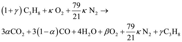
(1)
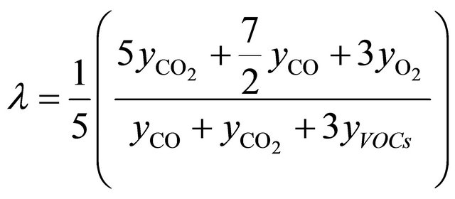
Air excess coefficient l is defined as quotient of amount of oxygen delivered to reaction zone and amount of oxygen used in combustion processes. For combustion reaction (1) this dependence can be written as:
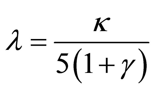 (2)
(2)
where coefficient κ was calculated from stoichiometric Equation (1):
 (3)
(3)
and coefficients a, b, g can be calculated from dependences:
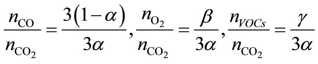 (4)
(4)
those equations after modifications are in form which allows to use molar fractions in calculations:
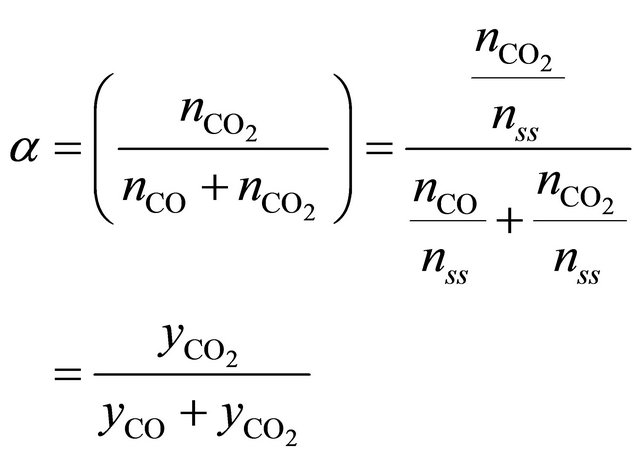 (5a)
(5a)
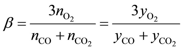 (5b)
(5b)
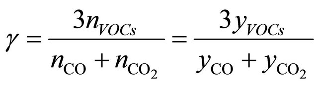 (5c)
(5c)
were:
nss is a sum o moles of all compounds in flue gases, dry condition;
nVOCs is an amount of unburnt compounds;
Equations (2)-(5) give possibility of calculate of air excess coefficient based on measured concentrations ( ,
,  ,
,  ,
, ):
):
NOTES
*Corresponding author.