Engineering
Vol. 4 No. 7 (2012) , Article ID: 20543 , 4 pages DOI:10.4236/eng.2012.47046
Reverse Engineering of Turbocharger Compressor Designs Based on Non-Parametric CAD Data
1CFturbo Software & Engineering GmbH, Dresden, Germany
2Kompressorenbau Bannewitz GmbH, Bannewitz, Germany
Email: oliver.velde@cfturbo.de, Ingolf.Lehmann@kbb-turbo.de
Received March 6, 2012; revised April 17, 2012; accepted April 25, 2012
Keywords: Turbocharger; Compressor; Reverse Engineering; Simulation; CFD
ABSTRACT
The improvement of turbocharger components—such as compressor—by means of virtual methods can be done most efficiently if those component’s geometries are given in a parameterized format. It is shown here how the geometric description of turbocharger compressors that have a neutral format (ASCII or STEP/IGES) can be transformed in a parameterized description. This description is then used to perform parameter variations which are validated via simulation methods like CFD. The parameterization of the geometry is therefore a very important step within the workflow of the virtual design of turbocharger components as without it the investigation of different geometries are very timeconsuming and expensive.
1. Introduction
CAD-data of components that have been produced over a long period are very seldom in a parameterized format which can be used in an optimization process. On the other hand those components have been proven to be well designed and documented, and are a good starting point for further developments.
If the aerodynamic behavior of a turbocharger compressor is to be improved especially fluid touched surfaces are needed in parameterized format. Parameters would be classical turbo machinery parameters like main dimension, blade angles, span wise description of blade geometry a. s. o. The transformation of blank CAD-data into a parameterized form is often time consuming and inexact.
It will be shown how any neutral format data of a turbocharger compressor can be transformed into a parameterized model fast and accurate. This model is afterwards exported into a CFD-package where the meshing is accomplished followed by a CFD-analysis. Therefore once the model is available, virtual methods can be used intensely.
Some comparisons with experiments are shown in order to validate the re-design. Also an example of the consequence of a parameter change on the basis of the re-design is given.
2. Re-Design
Very often data of old designs are available only as ASCII-format. With the turbo machinery design software CFturbo these data can be transformed into a parametric CAD-model [1]. Other neutral formats, such as STEP or IGES, are also possible as reference.
The procedure of the re-design needs some user interaction in order to get an exact representation of the reference design. For the calculation of information values that can be used for the valuation of the suitability, the following parameter should be given:
• Fluid properties: as ideal gas or as real gas with a compressibility factor.
• Best point: mass flow, speed, pressure ratio.
• Inlet conditions: pressure and temperature.
The main dimensions, that are hub and suction diameter as well as outlet width and diameter, have to be taken out of the reference geometry. Those values can be easily retrieved from any CAD-package but are very often known a priori.
Other important parameters should also be given, i.e. the size of the tip, direction of rotation, number of blades as well as splitter blades.
The meridional contour can be loaded directly if they are available as z-r-data, see Figure 1. These data can easily extracted from CAD data using a meridional section plane.
In CFturbo the meridional contour is represented by Bézier-splines. These splines have to be congruent to the loaded x-y-data in order to achieve an exact copy of the reference geometry, see Figure 2. The congruence can be made manually or automatically (Figure 3).
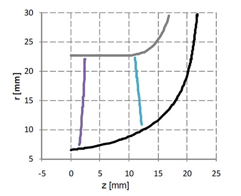
Figure 1. Meridional contour.
The shape of leading and trailing edge is straight by default but can be changed to freeform where again a Bézier-spline is used to represent any given form.
Blade angles: It is a strong advantage if the geometric variables can be extracted from the reference geometry in a way that they can be used directly in CFturbo. Such variables are e.g. radii, axial length, meridional and tangential co-ordinates as well as blade angles along mean lines, with whose help mean surfaces of the blades can be designed.
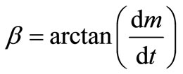
3D-data of any span are easily converted into variables (radius, meridional & tangential co-ordinate, blade angle) mentioned above by the following relations:
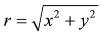 (1)
(1)
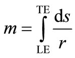 (2)
(2)
 (3)
(3)
 (4)
(4)
With these data all necessary variables are given for representation of the mean surfaces of the blades.
The mean surface is designed on the basis of mean lines lying in different spans. Mean lines can be given either as m-t-co-ordinates, or as β-t-co-ordinates. Again x-y-data of these pairs can be loaded into CFturbo followed by the match of the respective Bézier-spline description.
The blade profiling is the design step where a certain thickness is added to the mean surface on hub and shroud. Here almost any kind of profile can be realized as Bé- zier-splines with adjustable order as well as discrete profile data.
Some further finishing steps like leading edge rounding, trailing edge trimming, filleting a. s. o. may follow

Figure 2. Initial meridional contour with loaded hub contour.

Figure 3. Matched meridional contour.
the re-design done so far.
The procedure of the re-design of vaned and unvaned stators as well as of volutes is similar and is therefore not described here. The design steps are equally structured and allow both the calculation of parameters by CFturbo or their direct input.
3. Parameterized Geometry
The geometric model is now a fully parameterized one because the crucial parameters are now fixed. Those parameters are given in Table 1.
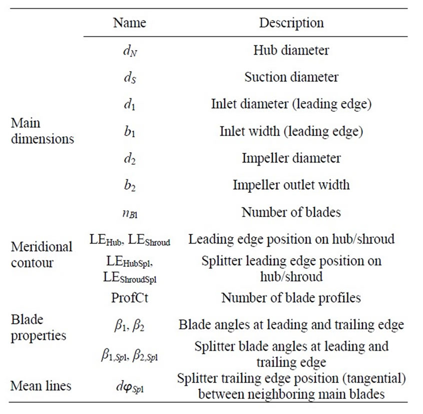
Table 1. Design parameter.
4. Example
The company Kompressorenbau Bannewitz (KBB) was founded in 1948 and has been active in the field of turbochargers (TC) since 1953. The main applications are medium-speed and high-speed 4 stroke diesel and gas engines [2-4].
Due to changed thermodynamic demands on the TC (two-stage-charging) imposed by the engine manufactures, pressure ratio per single compressor stage will decrease in the future. Stages of TC compressors produced 25 - 30 years ago, that were developed for similar pressure ratios, can serve as a good basis for further developments.
A certain compressor stage, comprehending of an impeller and a vaned stator, of the KBB-TC-family has been chosen. It was available as ASCII-data as well as CAD-model (see Figure 6, gold colored blades). The CAD-model was used as a criterion for the evaluation of the quality of the re-design geometry made by CFturbo. Both impeller and vaned stator show very good conformity.
From the available reference geometry the following data apart from the main dimensions and the best point could be extracted as x-y-data:
Meridional contour:
• z-r
Blade:
• β-m
• θ-m
• blade thickness
• x-y projection
Due to the fact that the blade design on the basis of the modification of β-m-data is more sensible than that on the basis of θ-m-data, it was tried to match reference data with re-design design data with the help of β-m.
In Figure 4 the β-distribution of hub and shroud are given. The match with the reference design is assessed by the difference of these distributions of reference design and re-design, see Figure 5.
The pure geometric assessment of the quality of the re-design has either been done by the comparison of the surfaces that represented the designs or by the comparisons of 2D-data that are available a priori or could be extracted from the original geometry. Since these data, especially the blade data like β-m or θ-m, are very much dependent on the correct choice of a mean surface an entire consistency of all 2D-data is very difficult to gain.
5. Comparison with Experiment
For the reference design apart from geometric information measured data are also available. These have been
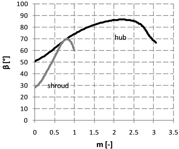
Figure 4. β-Distribution (re-design).
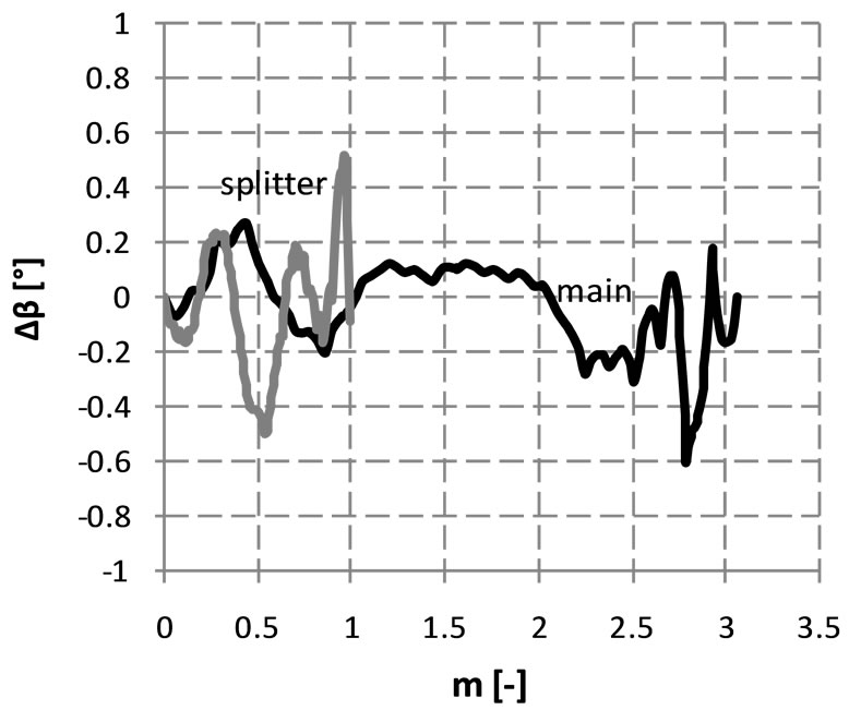
Figure 5. Differences between β-distributions of reference design and re-design (only main blades).
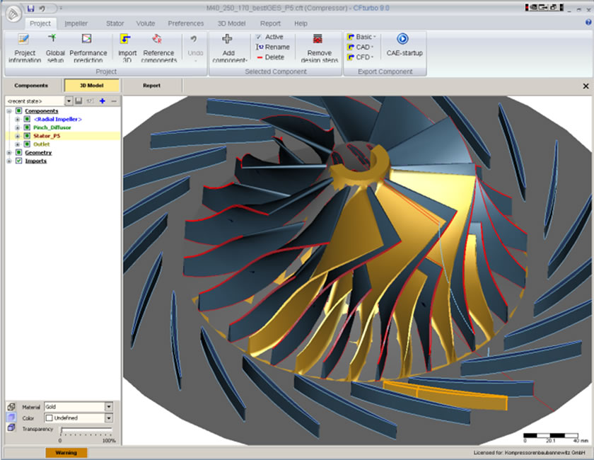
Figure 6. Reference and re-design in CFturbo (rotated).
used for the comparison with the re-design’s simulation data (see Figures 7-8).
One decisive difference between simulation and measurement setup of the compressor stage is that in the simulation a volute has not been considered. This explains especially at higher rotational speeds, the difference between measured and calculated efficiencies. The reason is the rising pressure loss in the volute at higher rotational speeds. The efficiency in the simulation is of course higher than those measured for the entire stage.
6. Design Variation and Validation
For the validation of parameter variations made on the basis of the re-design 3D-CFD-simulations have been accomplished. To this end the CFD-interfaces integrated in CFturbo were used.
The general purpose CFD program NUMECA has been utilized to set up a simulation model of the segment of the stage comprehending of inlet pipe, impeller, vaned stator and radial outlet diffuser. This has been done for both geometries, reference and re-design respectively.
The parameters to be changed were the leading edge blade angles (see Table 2) because they were suggested by CFturbo differently. Obviously the blockage (blade thickness) is considered differently by CFturbo for the calculation of leading edge angles than that of the original design. This is shown by the big difference of the incidence at hub.
Almost all parameters to be chosen can be calculated on the basis of balance equations and empirical knowledge in CFturbo. Appropriate algorithms are implemented.
In Table 3 some of the integral results of the simulation are given. It is discernible that the influence of the leading edge blade angle is very small when they are changed in the range as chosen.
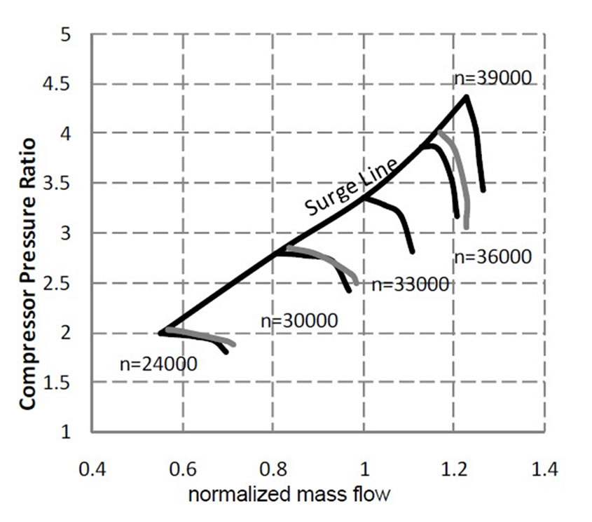
Figure 7. Comparison of measured (black) and simulated (grey) characteristics.

Figure 8. Comparison of measured (black) and simulated (grey) efficiencies.
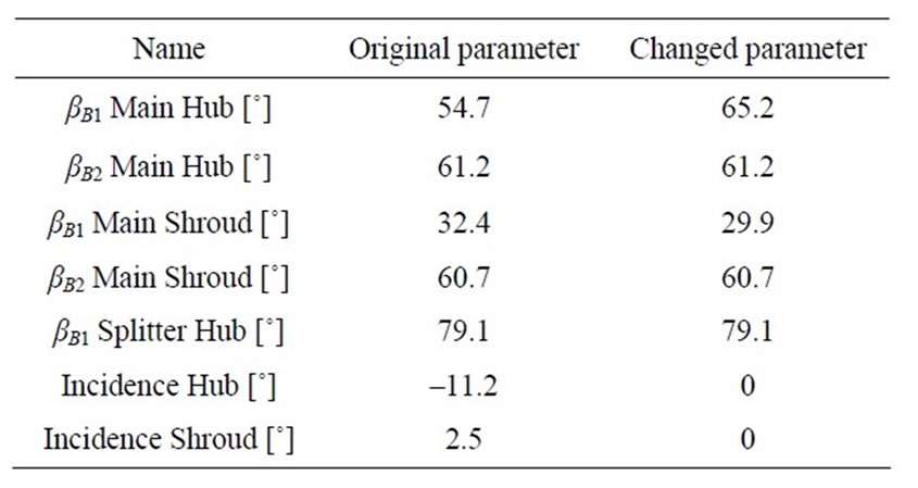
Table 2. Original and changed blade angles.

Table 3. Simulation results, integral values.
The analysis of the local flow fields shows almost identical results too. It is hardly discernible that differences exist at all (see for instance Figure 9).
Obviously the incidence changed in the given region has not a crucial influence on the aerodynamic. Certainly the thickness as well as the elliptic shape of the leading edge of the blades pay a contribution to this tolerance of the blade towards the change of the incidence.
Also closed looks at flow details do not reveal big differences (e.g. leading edge main blade at mid span, Figures 10 and 11 or 12 and 13 respectively).
The difference of the flow situation at the hub is much more noticeable because of the blade angle that has been determined with the blockage in design “changed” (see Table 2, local velocity plots at hub are not displayed). The development of the incidence from hub to shroud changes from negative to positive values. Very likely the incidence at mid span will therefore not be as big as at hub in the unchanged design, which might be another reason that the relative Mach Number distribution is very similar (see Figures 12-13).
The results of the simulations of both geometries yield
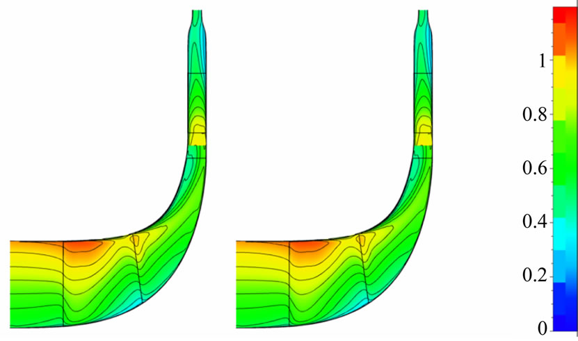
Figure 9. Relative mach number in the meridional cut, left reference design, right re-design.

Figure 10. Mid span relative mach number original design.

Figure 11. Mid span relative mach number re-design.
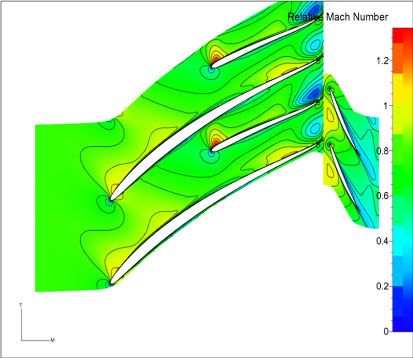
Figure 12. Mid span relative mach number original design (blade-to-blade view).

Figure 13. Mid span relative mach number re-design (bladeto-blade view).
the conclusion that the global aerodynamic performance of this type of compressor is hardly touched by a leading edge blade angle change.
7. Conclusions
From the manufacturer’s point of view the re-design process has been proven as exact and reliable. The parametric model can be used for derivative variants. Due to the utilization of CFturbo a broad data basis of most different impeller and stator sets can be created quickly. The parametric description of the geometries allows a very fast manipulation of geometries with respect to changing thermodynamic conditions like mass flow, pressure ratio or geometric restriction due to limited construction space.
The given example of a parameter change that was investigated numerically, shows the fast and efficient work flow that can be used once a fully parametric model is available.
REFERENCES
- G. Kreuzfeld and R. P. Müller, “An Advantageous Turbomachinery Design Method,” Compressor Tech Two, August-September 2011, pp. 78-82.
- V. Tiede and U. Kramer, “New Compressor Design for Compact Turbocharger Range HPR from KBB,” CIMAC Kongress, Hamburg, 7-10 Mai 2001.
- I. Lehmann, K. Buchmann and S. Käseberg, “HPR Range in Series Use—Ongoing Development of KBB Radial Turbine Type Turbochargers,” CIMAC Kongress, Wien, Paper Nr. 102, 21-24 Mai 2007.
- I. Lehmann, K. Buchmann and R. Drozdowski, “ATLKomponentenentwicklung für Druckverhältnisse über 5,” Presented at 12. Aufladetechnischen Konferenz Dresden, 27-28 September 2007.